


Service Manual
Microwave Oven
Model: KOR-61852S
KOR-61850N
KOR-61952S
DAEWOO ELECTRONICS CO., LTD.

PRECAUTIONS TO BE OBSERVED BEFORE AND DURING SERVICING TO AVOID POSSIBLE EXPOSURE TO EXCESSIVE MICROWAVE ENERGY
(a)Do not operate or allow the oven to be operated with the door open.
(b)Make the following safety checks on all ovens to be serviced before activating the magnetron or other microwave source, and make repairs as necessary: (1) Interlock operation, (2) proper door closing, (3) seal and sealing surfaces (arcing, wear, and other damage), (4) damage to or loosening of hinges and latches, (5) evidence of dropping or abuse.
(c)Before turning on microwave power for any service test or inspection within the microwave generating compartments, check the magnetron, wave guide or transmission line, and cavity for proper alignment, integrity, and connection.
(d)Any defective or misadjusted components in the interlock, monitor, door seal, and microwave generation and transmission systems shall be repaired, replaced, or adjusted by procedures described in this manual before the oven is released to the owner.
(e)A microwave leakage check to verify compliance with the Federal Performance Standard should be performed on each oven prior to release to the owner.
TABLE OF CONTENTS
PROPER USE AND SERVICE PRECAUTIONS |
3 |
SPECIFICATIONS |
4 |
FEATURE DIAGRAM |
5 |
INSTALLATION |
6 |
OPERATION |
7 |
MEASUREMENT OF THE MICROWAVE OUTPUT POWER |
8 |
MICROWAVE RADIATION TEST |
9 |
WIRING DIAGRAM |
10 |
CIRCUIT DESCRIPTION |
12 |
PRECAUTIONS FOR DISASSEMBLY AND REPAIR |
14 |
DISASSEMBLY AND ASSEMBLY |
15 |
INTERLOCK MECHANISM |
20 |
TROUBLE SHOOTING GUIDE |
22 |
COMPONENT TEST PORCEDURE |
24 |
SAFETY INTERLOCK CONTINUITY TEST |
25 |
EXPLODED AND PARTS LIST |
26 |
2

CAUTION : This Device is to be Serviced Only by Porperly Qualified Service Personnel. Consult the Service Manual for Proper Service Procedures to Assure Continued Compliance with the Federal Performance Standard for Microwave Ovens and for Precautions to be Taken to Avoid Possible Exposure to Excessive Microwave Energy.
PROPER USE AND SERVICE PRECAUTIONS
1.For Safe Operation
Damage that allows the microwave energy (that cooks or heats the food) to escape will result in poor cooking and may cause serious bodily injury to the operator.
IF ANY OF THE FOLLOWING CONDITIONS EXIST, OPERATOR MUST NOT USE THE APPLIANCE. (Only a trained service personnel should make repairs.)
1)A broken door hinge.
2)A broken door viewing screen.
3)A broken front panel, oven cavity.
4)A loosened door lock.
5)A broken door lock.
The door seal area and oven cavity surface be kept clean.
No grease, soil or spatter should be allowed to build up on these surfaces or inside the oven.
DO NOT ATTEMPT TO OPERATE THIS APPLIANCE WITH THE DOOR OPEN. The microwave oven has concealed switches to make sure the power is turned off when the door is opened. Do not attempt to defeat them.
DO NOT ATTEMPT TO SERVICE THIS APPLIANCE UNTIL YOU HAVE READ THIS SERVICE MANUAL.
2.For Safe Service Procedures.
1)If the oven is operative prior to servicing, a microwave emission check should be performed prior to servicing the oven.
2)If any ascertained oven unit is found to have excessive emission level 5mW/cm2, the service person should:
(a)inform the manufacturer, importer or assembler,
(b)repair the unit at no cost to the owner,
(c)attempt to ascertain the cause of the excessive leakage,
(d)tell the owner of the unit not to use the unit until the oven has been brought into compliance.
3)If the oven operates with the door open, the service person should tell the user not to operate the oven and contact the manufacturer immediately.
CAUTION
MICROWAVE RADIATION
PERSONNEL SHOULD NOT BE EXPOSED TO THE MICROWAVE ENERGY WHICH MAY RADIATE FROM THE MAGNETRON OR OTHER MICROWAVE GENERATING DEVICE IF IT IS IMPROPERLY USED OR CONNECTED. ALL INPUT AND OUTPUT MICROWAVE CONNECTIONS, WAVEGUIDES, FLANGES, AND GASKETS MUST BE SECURE. NEVER OPERATE THE DEVICE WITHOUT A MICROWAVE ENERGY ABSORBING LOAD ATTACHED. NEVER LOOK INTO AN OPEN WAVEGUIDE OR ANTENNA WHILE THE DEVICE IS ENERGIZED.
3
SPECIFICATIONS
|
|
ITEM |
SPECIFICATION |
||
|
|
KOR-6185/61952S |
|
KOR-61850N |
|
|
|
|
|
||
POWER SUPPLY |
|
230V 50Hz |
|
220V 50Hz |
|
|
|
|
|
|
|
|
|
POWER CONSUMPTION |
1200W |
|
1250W |
|
|
|
|
|
|
MICRO WAVE |
OUTPUT POWER |
800W (FULL MICROWAVE POWER) |
|||
|
|
|
|
|
|
|
|
FREQUENCY |
|
2450 MHz |
|
|
|
|
|
||
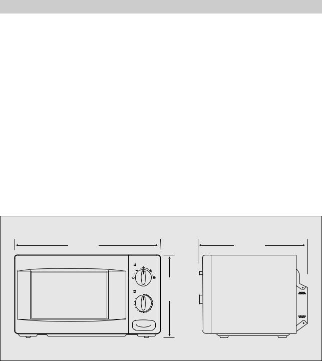
OUTSIDE DIMENSIONS (WXHXD) |
465 X 274 X 364 mm |
||||
|
|
|
|||
CAVITY DIMENSIONS(WXHXD) |
290 X 200 X 290 mm |
||||
|
|
|
|
||
NET WEIGHT |
|
APPROX 13.5Kg |
|||
|
|
|
|
||
TIMER |
|
35 min. DUAL SPEED |
|||
|
|
|
|
||
POWER SELECTIONS |
|
5 LEVELS |
|||
|
|
|
|
|
|
CAVITY VOLUME |
|
|
0.6 Cu. Ft. |
||
|
|
|
|
|
|
*Specifications are subject to change without notice.
465 |
|
|
364 |
|
0 |
1 |
274 |
|
|
|
2 |
35 |
|
|
3 |
30 |
|
|
4 |
25 |
|
|
5 |
20 |
|
|
6 |
15 |
|
8 |
7 |
10 |
9 |
|
4

FEATURES DIAGRAM
3 |
2 |
6 |
4 |
1 |
|
0 |
1 |
|
|
2 |
35 |
|
3 |
30 |
|
4 |
25 |
|
5 |
20 |
|
6 |
15 |
|
7 |
10 |
9 |
8 |
5 |
7 |
8 |
1 Saftey Interlock System.
9
10
11
2Door Viewing Screen - Allows viewing of food, the screen is designed so that light can pass through, but not the microwave.
3Door Hook - When the door is closed, it will automatically shut. If the door is opened while the oven is operating, the magnetron will immediately stop operating.
4 Oven Cavity
5Door Seal - Door seal maintains the microwave energy within the oven cavity and prevents micro leakage.
6Glass Cooking Tray - Made of special heat resistant glass. Food in a proper receptacle is placed on this tray for cooking.
7 Roller guide - This must always be used for cooking together with the glass cooking tray.
8Coupler - this fits over the shaft in the center of the oven’s cavity floor. This is to remain in the oven for all cooking.
9 Knob V.P.C - Used to select a microwave power level.
0 Knob timer - Used in setting cooking time for all functions.
qDoor Release button - By pushing this button the latch system cut of all circuits and stops the oven before the door is opened.
5

INSTALLATION
1.Steady, flat location
This microwave oven should be set on a steady, flat surface.
2.Leave space behind and side
All air vents should be kept a clearance. If all vents are covered during operation, the oven may overheat and, eventually, cause oven failure.
3.Away from radio, and TV sets
Poor television reception and radio interference may result if the oven is located close to a TV, Radio, or antenna, feeder and so on.
4.Away from heating appliances and water taps
Keep the oven away from hot air, steam or splash when choosing a place to position it, or the insulation might be adversely affected and breakdowns occur.
5.Power supply
•Check your local power source.
This microwave oven requires a current of approximately 6 amperes, 230V 50Hz. (220V 50Hz, KOR-6185ON) Use a receptacle that will accept the earth prong.
• Voltage Warning
The voltage used must be the same as specified on this Microwave Oven.
Using a higher voltage may result in a fire or other accident causing oven damage. Using low voltage will cause slow cooking.
We are not responsible for damage resulting from use of this Microwave Oven will a voltage or amperage fuse other than those specified.
• Power supply cord is about 1.0 meters long. Do not use an extension cord.
If the supply cord is damaged, it must be replaced by the manufacturer or its service agent or a similarly qualified person in order to avoid a hazard;
CAUTION : Do not under any circumstances cut or remove the round earthing prog from this pulg.
CAUTION : Maintenances works like the replacing of the power cable must be made by a technician qualified of the after-sales-services.
WARNING : This appliance must be earthed.
IMPORTANT
This wires in this mains lead are coloured inaccordance with the following code.
Green-and-yellow |
: Earth |
Blue |
: Neutral |
Brown |
: Live |
As the colours of the wires in the mains lead of this appliance may not correspond with the coloured markings identifying the terminals in your plug, proceed as follows:
The wire which is coloured green-and-yellow must be connected to the terminal in the plug which is marked with the letter ‘E’ or by the earth symbol or green-and-yellow.
The wire which is coloured blue must be connected to the terminal which is marked with the letter ‘N’ or coloured black.
The wire which is coloured brown must be connected to the terminal which is marked with the letter ‘L’ or coloured red.
6.Examine the oven after unpacking for any damage such as:
Dents, A misaligned door, Broken door, A dents in cavity. If any of the above are visable, do not install this oven.
6
OPERATION
1
2
3
4
Connect the main lead to an electrical outlet.
After placing the food in a suitable container, open the oven door and put it on the glass tray. The glass tray must always be in place during cooking.
CLOSE THE DOOR securely.
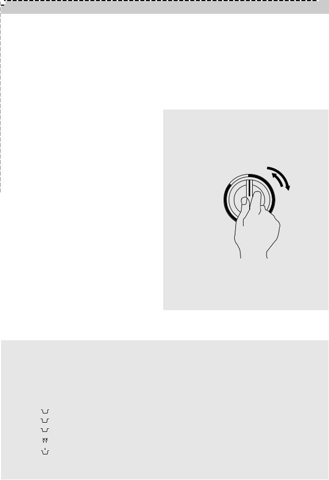
Choose cooking power level by setting V.P.C. |
|
|
knob to the desired position. |
NOTE : |
|
Refer to cookbook for recommended power |
1. When setting Timer for less than 2 minutes, turn |
|
levles. |
||
the Timer past 2 minutes and then return to the |
||
|
||
|
correct timer setting. |
Determine cooking time. Consult cookbook for 5 recipe timing.
¢”Oven light turns on and cooling fan starts to operate. Microwave cooking starts.
You may open the door while the oven is 6 operating. As soon as the door is opened, the safety mechanisms stop the generation of microwave power and the operation of cooking
timer.
If you wish to change the time during cooking, simply adjust the Timer to the desired time.
|
0 |
1 |
|
|
2 |
35 |
|
3 |
30 |
|
4 |
25 |
|
5 |
20 |
|
|
15
10
When the timer reaches zero, a bell will ring and 7 the unit will turn off.
¢”Oven light turns off.
If additional cooking time is needed and the door is closed, the oven will automatically start when the Timer is reset.
2.Various clicking noises may be heard when turning the V.P.C. Knob. This is normal and does not affect the operation of your microwave oven.
Variable power cooking
ON and OFF cycle time of mechanicial V.P.C. switch is 30 seconds.
When the V.P.C. knob is set to the desired position and timer knob turns to the desired position, the V.P.C switch has a cycle (ON/OFF time (sec)) listed below.
Variable power setting |
ON/OFF time (SEC) |
POWER |
|||
|
|
|
|
|
|
|
|
|
(HIGH) |
30/0 |
100% |
|
|
|
|||
|
|
|
|||
|
|
|
|
|
|
|
|
|
(MED HIGH) |
23.2/6.8 |
77% |
|
|
|
|||
|
|
|
|||
|
|
|
(MEDIUM) |
16.5/13.5 |
55% |
|
|
|
|||
|
|
||||
|
|
|
|
|
|
|
|
|
(DEFROST) |
9.8/20.2 |
33% |
|
|
|
|||
|
|
|
|
|
|
|
|
|
(WARM) |
5/25 |
17% |
|
|
|
|
|
|
7
MEASUREMENT OF THE MICROWAVE OUTPUT POWER
Microwave output power can be checked by indirectly measuring the temperature rise of a certain amount of water exposed to the microwave as directed below.
Procedure
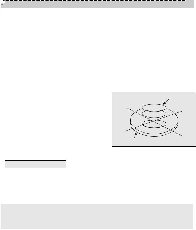
1.Microwave power output measurement is made with the microwave oven supplied at rated voltage and operated at its maximum microwave power setting with a load of 1,000±5cc of potable water.
2.The water is contained in a cylindrical borosilicate glass vessel having a maximum material thickness of 3 mm and an outside diameter of approximately 190 mm.
3.The oven and the empty vessel are at ambient temperature prior to the start of the test. The initial temperature of the water is 10±2˚C(50±3.6˚F).
It is measured immediately before the water is added to the vessel. After addition of the water to the vessel, the load is immediately placed on the center of the shelf which is in the lowest normal position.
4.Microwave power is switched on.
5.Heating time should be exactly 52 seconds.
Heating time is measured while the microwave generator is operating at full power.
The filament heat-up time for magnetrons is not included.
6.The initial and final water temperatures are selected so that the maximum defference between the ambient and final water temperature is 5K.
Water Load
Tray
7. The microwave power output P in watts is calculated from the following formula:
P = 4187 X T/t
•T is actual temperature rise.
•t is the heating time.
The power measured should be 800W±10%.
CAUTION :
1.Water load should be measured exactly to 1 liters.
2.Input power voltage should be exactly 230 volts as specified.
3.Ambient temperature should be 20±2˚C (68±3.6˚F)
8
MICROWAVE RADIATION TEST
WARNING
•Make sure to check the microwave leakage before and after repair or adjustment.
•Always, start measuring of an unknown field to assure safety for operating personnel from microwave energy.
•Do not place your hands into any suspected microwave radiation field unless the safe density level is known.
•Care should be takent not to place the eyes in direct line with the source of microwave energy.
•Slowlyapproach the unit under test until the radiometer reads an appreaciable microwave leakage from the unit under the test.
Procedure
A)Prepare Microwave Energy Survey Meter, 600cc glass beaker, glass thermometer 100˚C or 212˚F.
B)Pour 275cc±15cc of tap water initially at 20±5˚C(68±9˚F) in the 600cc beaker with an inside diameter of approx. 9.5cm (3.5 in).
C)Place it at the center of the tray and set it in a cavity.
D)Close the door and operate the oven.
E)Measure the leakage by using microwave energy survery meter with dual ranges, set to 2450 MHz.
-Measured radiation leakage must not exceed the values prescribed below.
•Leakage for a fully assembled oven with door normally closed must be less than 4mW/cm2.
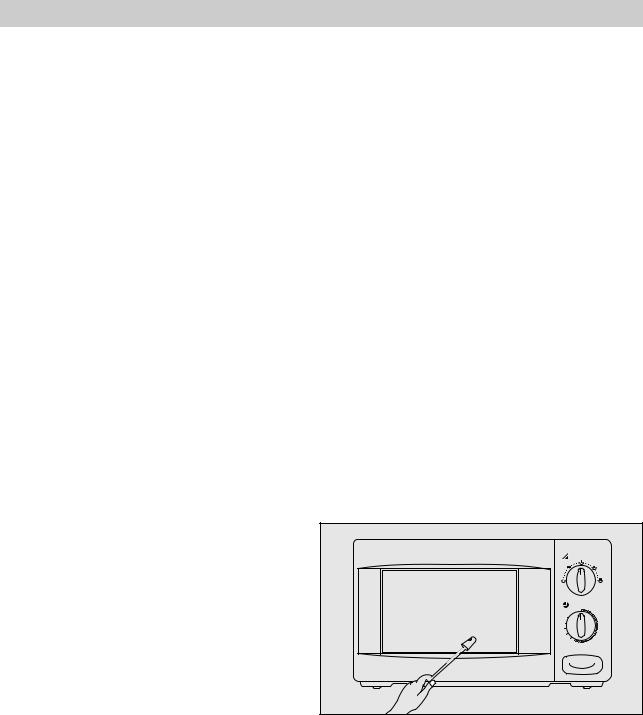
-When measuring the leakage, always use the 2 in (5cm) space cone with probe. Hold the probe perpendicular to the cabinet, door. Place the space cone of the probe on the door, cabinet, door seam, door viewing screen, the exhaust air vents and the suction air vents.
-Measuring should be in a counter-clockwise direction at a rate of 1 inch/sec. If the leakage of the cabinet door seam is unkow, move the prove more slowly.
|
0 |
1 |
|
|
2 |
35 |
|
3 |
30 |
|
4 |
25 |
|
5 |
20 |
|
6 |
15 |
|
7 |
10 |
9 |
8 |
-When measuring near a corner of the door, keep the probe perpendicular to the areas making sure the probe end at the base of the cone does not get closer than 2 inches from any metal.
If it does, erroneous reading may result.
9
10
|
|
|
PRIMARY |
|
TIMER ASSY |
|
|
|
|
SLOW ACTING |
|
|
|
INTERLOCK |
|
TIMER |
|
|
|
|
|
|
|
|
|
|
|
|
|
|
RELAY ASS'Y |
|
|
|
|
SWITCH(UPPER) |
1 |
SWITCHV.P.C |
3 |
|
|
|
|
|
|
|
|
|
|
|
||||
|
|
|
RD |
WH |
|
|
|
|
RD |
BK |
|
|
|
RD |
|
|
2 |
|
|
|
|
POWER SUPPLY : |
|
|
|
|
|
|
|
|
|
GY |
SINGLE PHASE ~ ONLY |
|
|
NO |
|
GY |
GY |
|
|||
|
|
|
|
|
|
|
|
|
|
|
|
FILTER ASS'Y |
COM |
NC |
|
|
|
|
|
|
|
BR(BK) |
FUSE |
|
INTERLOCK |
|
|
|
|
|
|
|
BL(WH) |
L |
L |
MONITOR |
|
TM |
|
CL |
|
GM |
FM |
|
|
SWITCH |
|
|
|
|
|
|
|
|
GE(GN) |
N |
N |
|
|
|
|
|
|
|
|
|
|
|
|
|
|
|
|
|
|
|
|
GN |
|
|
M |
|
|
|
|
|
|
|
|
|
BK |
|
GY |
GY |
GY |
|||
|
|
|
|
|
BL |
|
|
|
|
BL |
|
|
|
WH |
|
|
|
|
|
|
|
|
|
|
|
|
|
|
|
|
WH |
|
|
|
|
SECONDARY |
|
|
|
|
|
|
|
|
|
|
INTERLOCK SWITCH |
|
|
|
|
|
||
NOTE : |
|
|
|
|
|
|
|
|
|
|
NOTE RD : RED |
|
OR : ORANGE |
CL : CAVITY LAMP |
|
|
|
|
[CONDITION] |
||
NOTE WH : WHITE |
|
BL : BLUE |
FM : FAN(BLOWER) MOTOR |
|
|
DOOR : CLOSED |
||||
NOTE BK : BLACK |
|
GY : GRAY |
GM : GEARED MOTOR |
|
|
|
TIMER : ON |
|||
NOTE GN : GREEN |
|
GE : GREEN/YELLOW |
TM : TIMER MOTOR |
|
|
|
|
V.P.C. : HIGH |
||
NOTE BR : BROWNNOTE |
|
|
V.P.C : VARIABLE POWER CONTROLLER |
|||||||
HIGH VOLTAGE
TRANSFORMER |
|
RD |
RD |
H.V. |
|
FUSE |
|
H.V. |
|
CAPACITOR |
|
|
MAGNETRON |
H.V. DIODE |
|
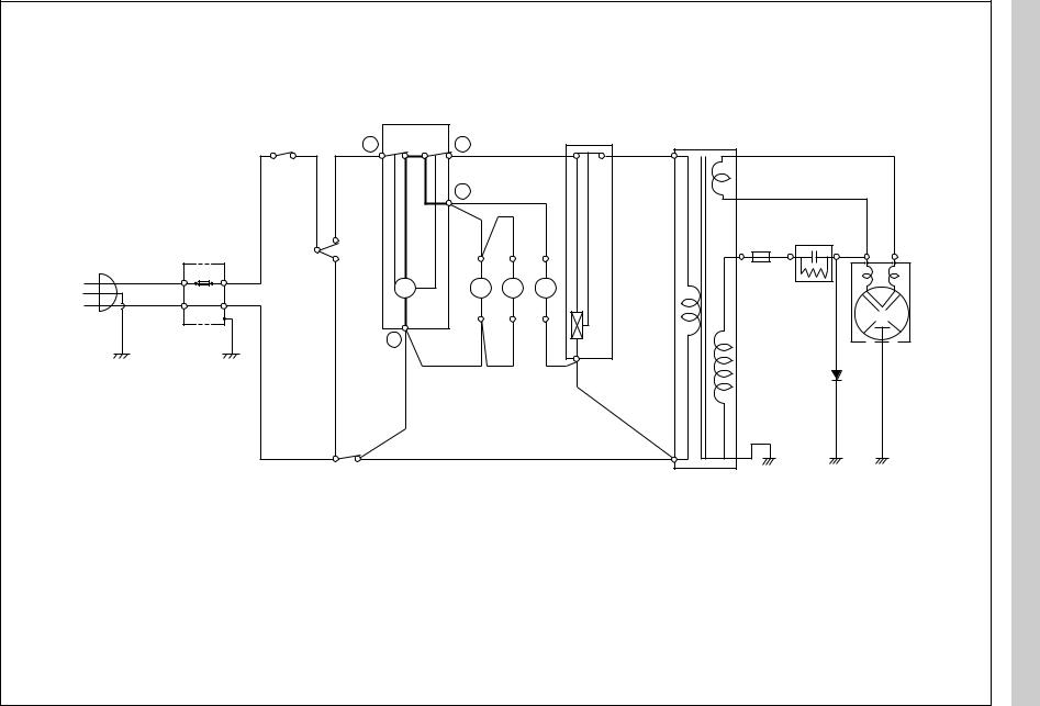
TYPE) RELAY ACTING (SLOW DIAGRAM WIRING
 Loading...