


KOR-632G0S
Table of contents
 Loading...
Service Manual
Microwave Oven
Model: KOR-632G0S
DAEWOO ELECTRONICS CO., LTD.
KOR-632H0S
KOR-862H0S
KOR-862H0S
S/M No. : R632G0S001
SAFETY AND PRECAUTIONS........................................................................................................... 2
1. FOR SAFE OPERATION .............................................................................................................. 2
2. FOR SAFE SERVICE PROCEDURES ......................................................................................... 2
SPECIFICATIONS............................................................................................................................... 3
EXTERNAL VIEW................................................................................................................................ 4
1. OUTER DIMENSION..................................................................................................................... 4
2. FEATURE DIAGRAM.................................................................................................................... 5
3. CONTROL PANEL........................................................................................................................ 6
INSTALLATI ON ............... .................. ............... .................. ............... ................. ............... ................. 8
OPERATIONS AND FUNCTIONS....................................................................................................... 9
DISASSEMBLY AND ASSEMBLY...................................................................................................... 10
INTERLOCK MECHANISM AND ADJUSTMENT............................................................................... 17
TROUBLE SHOOTING GUIDE .......... ... ......... ... .................. ... ......... ... ........ ... ... ......... ... ......... ... ........... 18
MEASUREMENT AND TEST...................................................... ......... ................. ......... ......... ........... . 22
1. MEASUREMENT OF THE MICROWAVE POWER OUTPUT ...................................................... 22
2. MICROWAVE RADIATION TEST................................................................................................. 23
3. COMPONENT TEST PROCEDURE............................................................................................. 24
WIRING DIAGRAM.............................................................................................................................. 25
PRINTED CIRCUIT BOARD................................................................................................................ 26
1. CIRCUIT CHECK PROCEDURE .................................................................................................. 26
2. PCB CIRCUIT DIAGRAM.............................................................................................................. 29
3. P.C.B. LOCATION NO. ................................................................................................................. 30
EXPLODED VIEW AND PARTS LIST................................................................................................. 32
1. DOOR ASSEMBLY....................................................................................................................... 32
2. CONTROL PANEL ASSEMBLY.................................................................................................... 32
3. TOTAL ASSEMBLY....................................................................................................................... 32
(a) Do not operate or allow the oven to be operated with the door open.
(b) Make the following safety checks on all ovens to be serviced before activating the magnetron or other microwave
source, and make repairs as necessary: (1) Interlock operation, (2) Proper door closing, (3) Seal and sealing
surfaces (arcing, wear, and other damage), (4) Damage to or loosening of hinges and latches, (5) Evidence of
dropping or abuse.
(c) Before turning on power to the microwave oven for any service test or inspection within the microwave
generating compartments, check the magnetron, wave guide or transmission line, and cavity for proper
alignment, integrity, and connections.
(d) Any defective or misadjusted components in the interlock, monitor, door seal, and microwave generation and
transmission systems shall be repaired, replaced, or adjusted by procedures described in this manual before the
oven is released to the owner.
(e) A microwave leakage check to verify compliance with the Federal performance standard should be performed on
each oven prior to release to the owner.
PRECAUTIONS TO BE OBSERVED BEFORE AND
DURING SERVICING TO AVOID POSSIBLE
EXPOSURE TO EXCESSI VE MICR OWAV E ENERGY

SAFETY AND PRE CAUTIONS
1. FOR SAFE OPERATION
Dam age that allows the microwave energy (that cooks or heats the food) to escape will res u lt in poor cooking and m ay cause
serious bodily injury to the operator.
IF ANY OF THE FOLLOWING CONDITION S EXIST, OPERATOR MUST NOT USE THE APPLIAN CE.
(Only a trained service personnel should make repairs.)
1) A broken door hinge.
2) A broken door viewing screen.
3) A broken front panel, oven cavity.
4) A loosened door lock.
5) A broken door lock.
The door gasket plate and oven cavity surface should be kept clean.
No grease, soil or spatter should be allowed to build up on these surfaces or inside the oven.
DO NOT ATTEMPT TO OPERATE THIS APPLIANCE WITH THE DOOR OPEN. The microwave oven has concealed switches
to make sure the power is turned off w hen the door is opened. D o not attempt to defeat them.
DO NOT ATTEMPT TO SERVICE THIS APPLIANCE UNTIL YOU HAVE READ THIS SERVICE MANUAL.
2. FOR SAFE SERVICE PROCEDURES
1) If the oven is operative prior to servicing, a microwave emission check should be perform ed prior to servicing the oven.
2) If any certified oven unit is found to servicing, a microwave em ission check should be performed prior to servicing the oven.
(a) inform the manufacturer, importer or assembler,
(b) repair the unit at no cost to the ow ner,
(c) attempt to ascertain the cause of the excessive leakage,
(d) tell the owner of the unit not to use the unit until the oven has been brought into compliance.
3) If the oven operates with the door open, the service person should tell the user not to operate the oven and contact the
manufacturer im m ediately.
IMPORTA NT
The wire in this m ains lead coloured in accordance w ith the following code.
Green-and-yellow : Earth
Blue : Neutral
Brown : Live
As the colours of the wires in the manins lead of this appliance may not correspond w ith the coloured m arkings
identifying the terminals in your plug, proceed as follows.
The wire which is coloured green-and-yellow m ust be connected to the termianl in the plug w hich is marked with the
letter ‘E’, earth symbol or coloured green-and-yellow.
The wire which is coloured blue m ust be connected to the terminal which is m arked with the letter ‘N’ or
coloured black.
The wire which is coloured brown m ust be connected to the terminal which is marked with the letter ‘L’ or
coloured red.
This oven is designed for counter-top use only.
NOTE
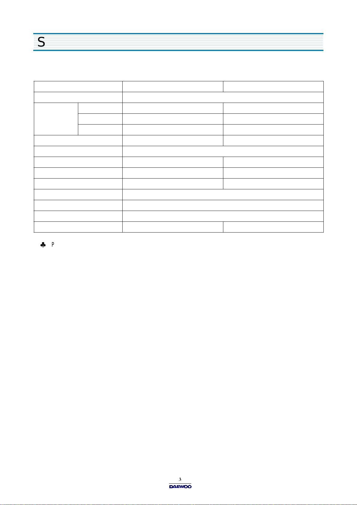
SPECIFICATIONS
SPECIFICATIONS ARE SUBJECT TO CHANGE WITHOUT NOTICE.
MODEL KOR-632G/H KOR-862G/H
POW ER SU PPLY 230V-50Hz, SINGLE PH ASE W ITH EARTHING
POW ER
CONSUMPTION
MICROW AVE 1200W 1350W
GRILL
COMBINATION
MICROWAVE ENERGY OUTPUT 800W 900W
MICROWAVE FREQUENCY 2450MHz
OUTSIDE DIMENSIONS (W X H X D) 465 x 279 x 360mm (18.3 x 11.0 x 14.2 in.) 495 x 294 x 388mm (19.5 x 11.6 x 15.3 in.)
CAVIT Y DIMENS IONS (W X H X D ) 290 x 220 x 306 mm (11.4 x 8.7 x 12.0 in.) 320 x 244 x 338mm (12.6 x 9.6 x 13.3 in.)
NET W E IGHT APPRO X . 13Kg ( 28.7lbs.) APPRO X. 15Kg ( 33.1lbs.)
TIMER 59 min. 90 sec.
FUNCTION SELECTIONS MICROWAVE
POW ER SE LECTIONS 10 LEVELS
CAVIT Y VOLUM E 0.7 C u.Ft. 0.9 C u.Ft.
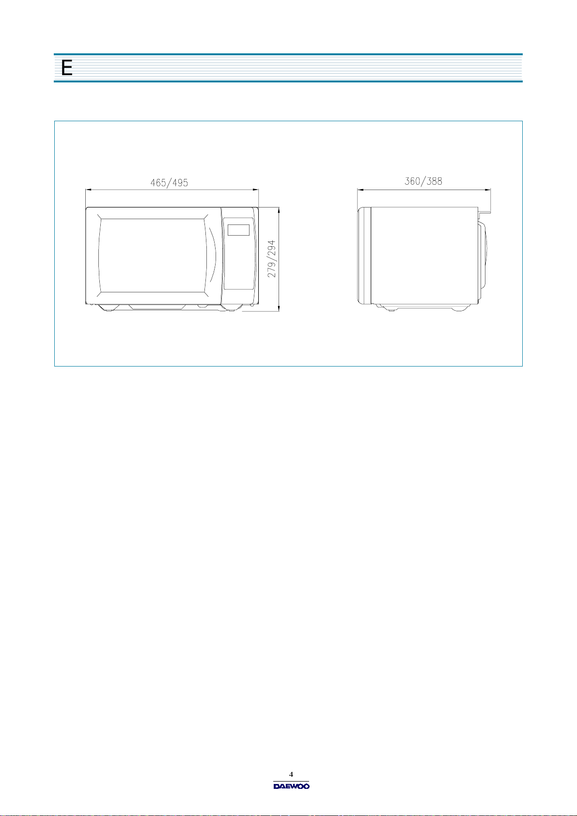
EXTERNAL VIEW
1. OUTER DIMENSION
EXTERNAL VIEW
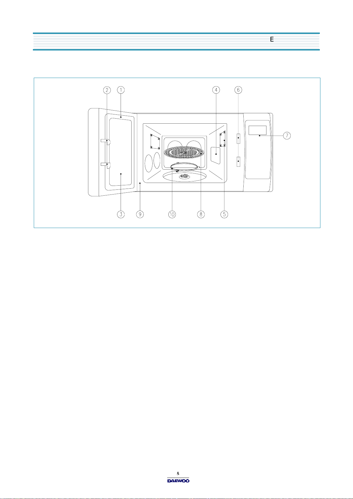
2. FEATURE DIAGRAM
1. DOOR SEAL
Door seal m aintains the microw ave within the oven cavity and prevents microwave leakage.
2. DOOR HOOK
When door is closed, it will automatically lock shut. If door is opened while oven is operating, magnetron tube will
immediately stop operating.
3. DOOR SCREEN
Allows viewing of food. M icrowave cannot pass through perforations in screen.
4. SPATTER SHIELD
Protects the microwave outlet from splashes of cooking foods.
5. OVEN LAMP
Automatically turns on during oven operating.
6. SAFETY INTERLOCK SYSTEM
7. CONTROL PANEL
8. GLASS COOKING TRAY
Made of special heat resistant glass. The tray must alw ays be in proper position before operating. Do not cook food
directly on the tray..
9. OVEN FRONT PLATE
10. ROLLER GUIDE
Supports the glass cooking tray.
EXTERNAL VIEW
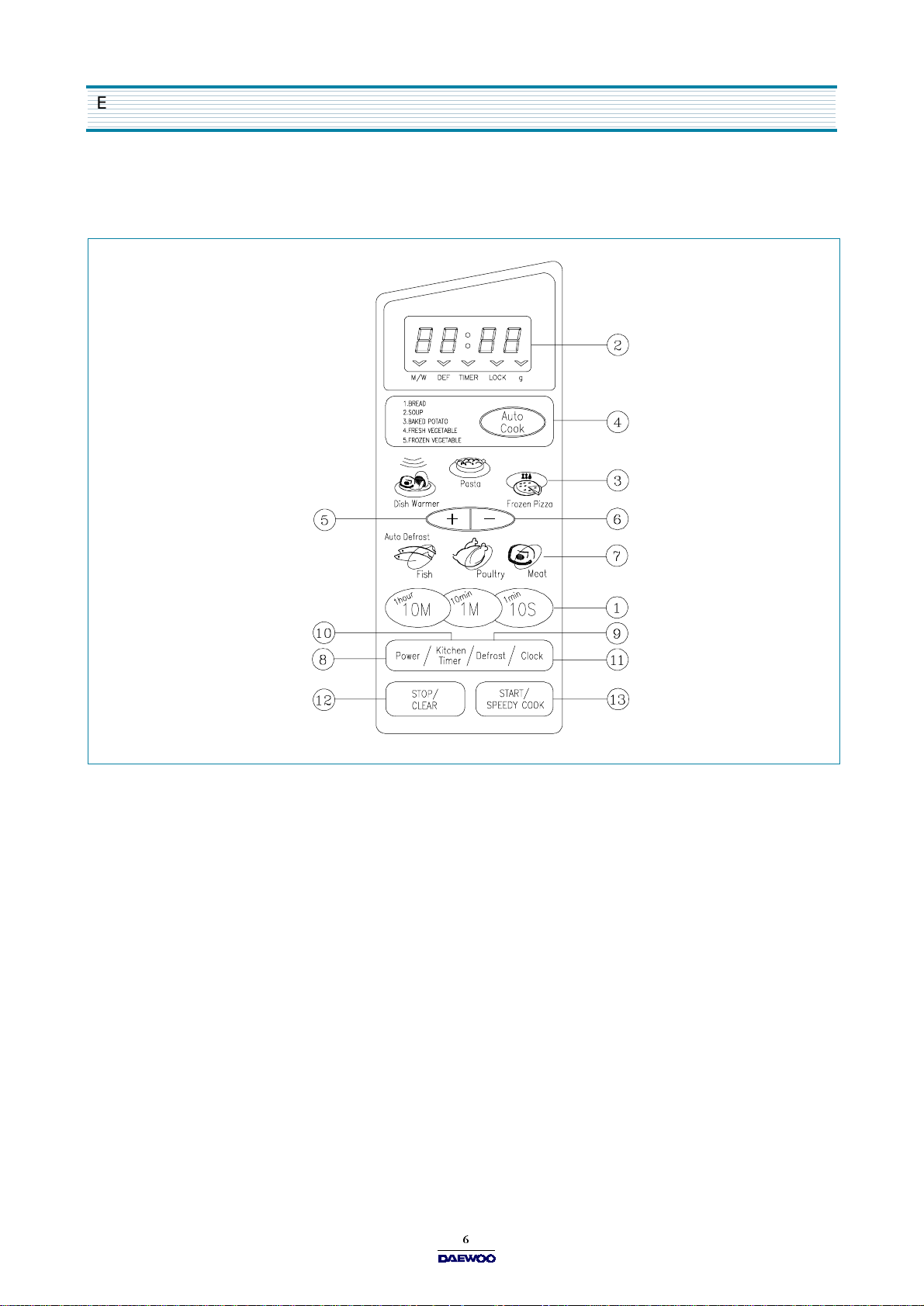
3. CONTROL PANEL
(1) KOR-632G 0S /862G0S
1. Time set pad -
Used to set the cooking time and the present time.
2. Disp lay
- Cooking time, power level, indicators and present time are displayed.
3. One touch
- Used to cook or reheat specific quantities of food.
4. Auto cook
- Used to cook or reheat.
5. More
- Used to add time to cooking.
6. Less
- Us ed to remove ti me from coo k i n g.
7. Auto Defrost
- Used to defrost foods.(for weight)
8. Power
- Us ed to se t powe r l e ve l.
9. Defrost
- Us ed to d efrost foo d s.(for time)
10. Kitchen Timer
- Used as a minute timer, delay cooking, hold setting after cooking.
11. Clock
- Used to set clock .
12. Stop/Clear
- Used to stop the oven operation or to delete the cooking data.
13. Start/Speedy cook
- Used to start the oven and also used to set a reheat time.
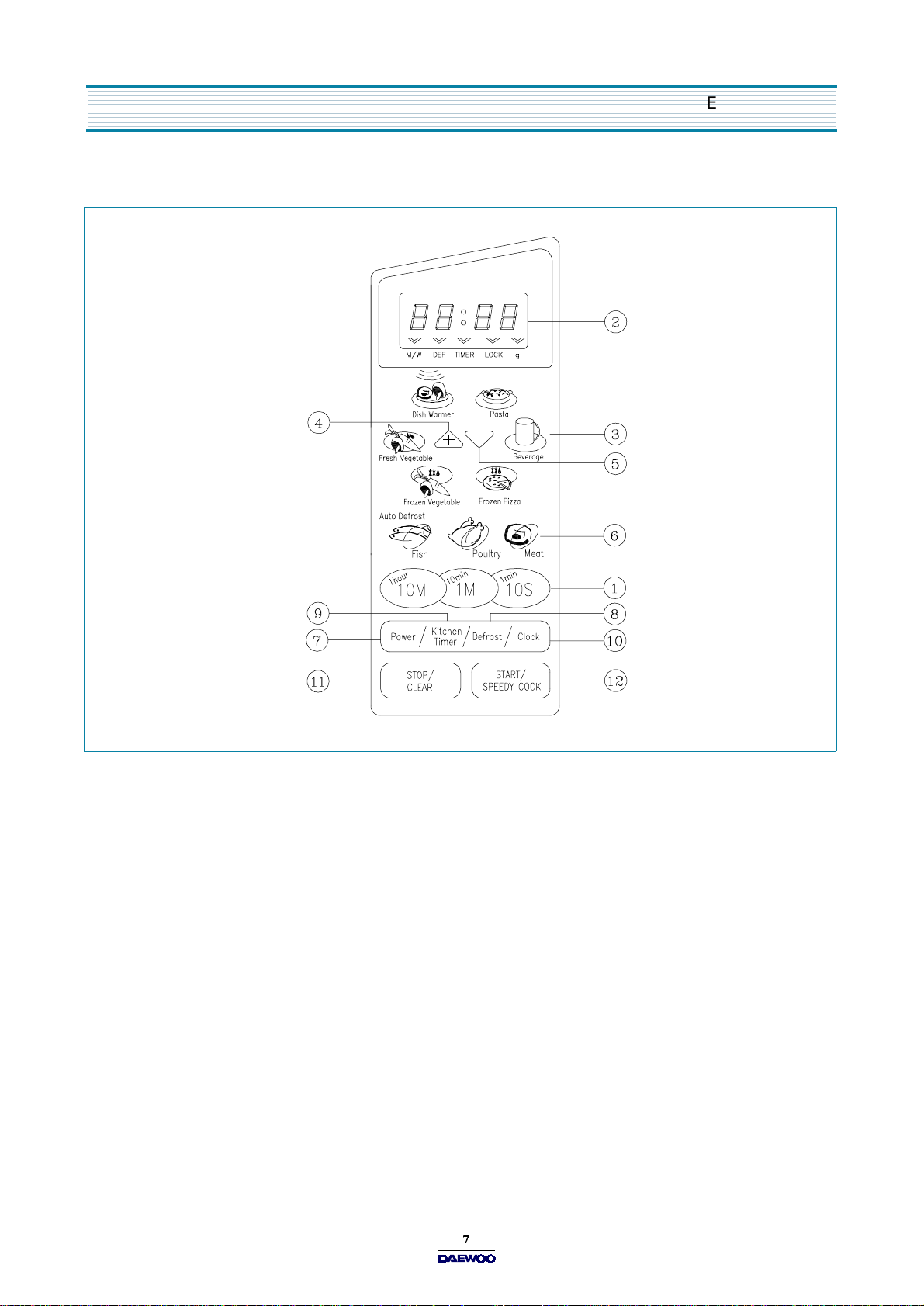
EXTERNAL VIEW
(2) KOR-632H 0S/862H0S
1. Time set pad
- Used to set the cooking time and the present time.
2. Disp lay
- Cooking time, power level, indicators and present time are displayed.
3. One touch
- Used to cook or reheat specific quantities of food.
4. More
- Used to add time to cooking.
5. Less
- Us ed to remove ti me from coo k i n g.
6. Auto Defrost
- Used to defrost foods.(for w eight)
7. Power
- Us ed to se t powe r l e ve l.
8. Defrost
- Us ed to d efrost foo d s.(for time)
9. Kitchen Timer
- Used as a minute timer, delay cooking, hold setting after cooking.
10. Clock
- Used to set clock.
11. Stop/Clear
- Used to stop the oven operation or to delete the cooking data.
12. Start/Speedy cook
- Used to start the oven and also used to set a reheat time.

INSTALLATION
1. Stead y, flat location
This microwave oven should be set on a steady, flat surface.
This microwave oven is designed for counter top use only.
2. Leave space behind an d side
All air vents should be kept a clearance. If all vents are covered during operation, the oven m ay overheat and, eventually,
cause failure.
3. Away from radio and TV sets
Poor television reception an d radio interference may result if the o ven is located close to a TV, radio, antenna or feeder and so on.
Positio n the oven as far from them as possible.
4. Away from heating appliances and water taps
Keep the oven away from hot air, steam or splash w hen choosing a place to position it, or the insulation might be adversely
affected and breakdowns occur.
5. Power supply
Check your local pow er source.
This m icrowave oven requires a current of approximately 6 amperes, 230 Volts, 50 Hz.
Power supply cord is about 0.8 meters long.
The voltage used must be the same as specified on this oven. U sing a higher voltage may result in a fire or other accident
causing oven damage. Using low voltage will ca u s e s lo w c ook in g . We ar e n o t re s ponsible for dam age resulting from use
of this oven with a voltage of ampere fuse other than those specified.
This appliance is supplied with cable of special type, which, if dam aged, must be repaired with cable of same type.
Such a cable can be purchased from DAEWO O and must be installed by a Qualified Person.
6. Examine the oven after unpacking for any damage such as:
A m isaligned door, broken door or a dent in cavity.
If any of the above are visible, DO NOT INSTALL, and notify dealer immediately.
7. Do n o t o pe rate th e o v e n if it is c old e r th an roo m temp e r a tu r e
(This m ay occur during delivery in cold weather.) Allow the oven to become room temperature before operating.
This appliance must be earthed. In the event of an electrical short circuit, earthing reduces the risk of the electric shock by
providing an escape wire for the electric current. This appliance is equipped with a cord having a earthing wire with a earthing
plug. The plug must be plugged into an outlet that is properly installed and earthed.
WARNING
Improper use of the earthing plug can result in a risk of electric shock. C onsult a qualified electrician or serviceman if
the earthing instructions are not completely understood, or if doubt exists as to whether the appliance is properly
earthed, and either : If it is necessary to use an extension cord, use only a 3-wire extension cord that has a 3-blade
earthing plug, and a 3-slot receptacle that will ac cep t th e p lug on th e appliance. T he m arked rating of the extension
cord should be equal to or greater than the electrical rating of the appliance, or Do not use an extension cord.
EARTHING INSTRUCTIONS
1. Connect the main lead to an electrical outlet.
2. After placing the food in a suitable container, open the oven door and put it on the glass tray. The glass tray must always
be in place during cooking.
3. Close the door securely.
4. When the oven door is opened, the light turns off.
5. The oven door can be opened at any time during operation by touching the door release button on the control panel.
The oven will automatically shut off. To restart the oven, close the door and then touch STA RT.
6. Each time a pad is touched, a BEEP will sound to acknowledge the touch.
7. The oven automatically cook on full power unless set to a lower power level.
8. The display will show :0 when the oven is plugged in.
9. Time clock returns to the present time w hen the cooking time ends.
10. W hen the STOP /CLEAR pad is touched during the oven operation, the oven stops cooking and all information retained.
To erase all information (except the present tim e), touch the STO P/CLEAR pad once more. If the oven door is opened
during the oven operation, all information is retained.
11. If the START pad is touched and the oven does not operate, check the area between the door and door is closed
securely. The oven will not start cooking under the door is completely closed or the program has been reset.
Wattage output chart
The power level is set by pressing the Power pad. The chart shows the display, the pow er level and the percentage of
power.
Touch Power pad. Power level (Display) Approximate Percentage of Power
Once P-HI 100 %
Tw ice P-9 0 90 %
3 times P-80 80 %
4 times P-70 70 %
5 times P-60 60 %
6 times P-50 50 %
7 times P-40 40 %
8 times P-30 30 %
9 times P-20 20 %
10 times P-10 10 %
11 times P -00 0 %
OPERATIONS AND FU NCTIONS
Make sure the oven is properly installed and plugged into the electrical outlet.
DISASSEMB LY AND ASSEMBLY
Cautions to be observed when trouble shooting
Unlike many other appliances, the microwave oven is high-voltage, high-current equipm ent.
It is completely safety during normal operation. However, carelessness in servicing the oven
can result in an electric shock or possible danger from a short circuit.
You are asked to observe the following precautions carefully.
1. Always remove the power plug from the outlet before servicing.
2. Use an insulated screwdriver and ware rubber gloves when servicing the high voltage side.
3. Discharge the high voltage capacitor before touching any oven components or wiring.
(1) Check the earthed.
Do not operate on a two-wire extension cord.
The microwave oven is designed to be used with earthed.
It is imperative, therefore, to makes sure it is earthed properly
before beginning repair work.
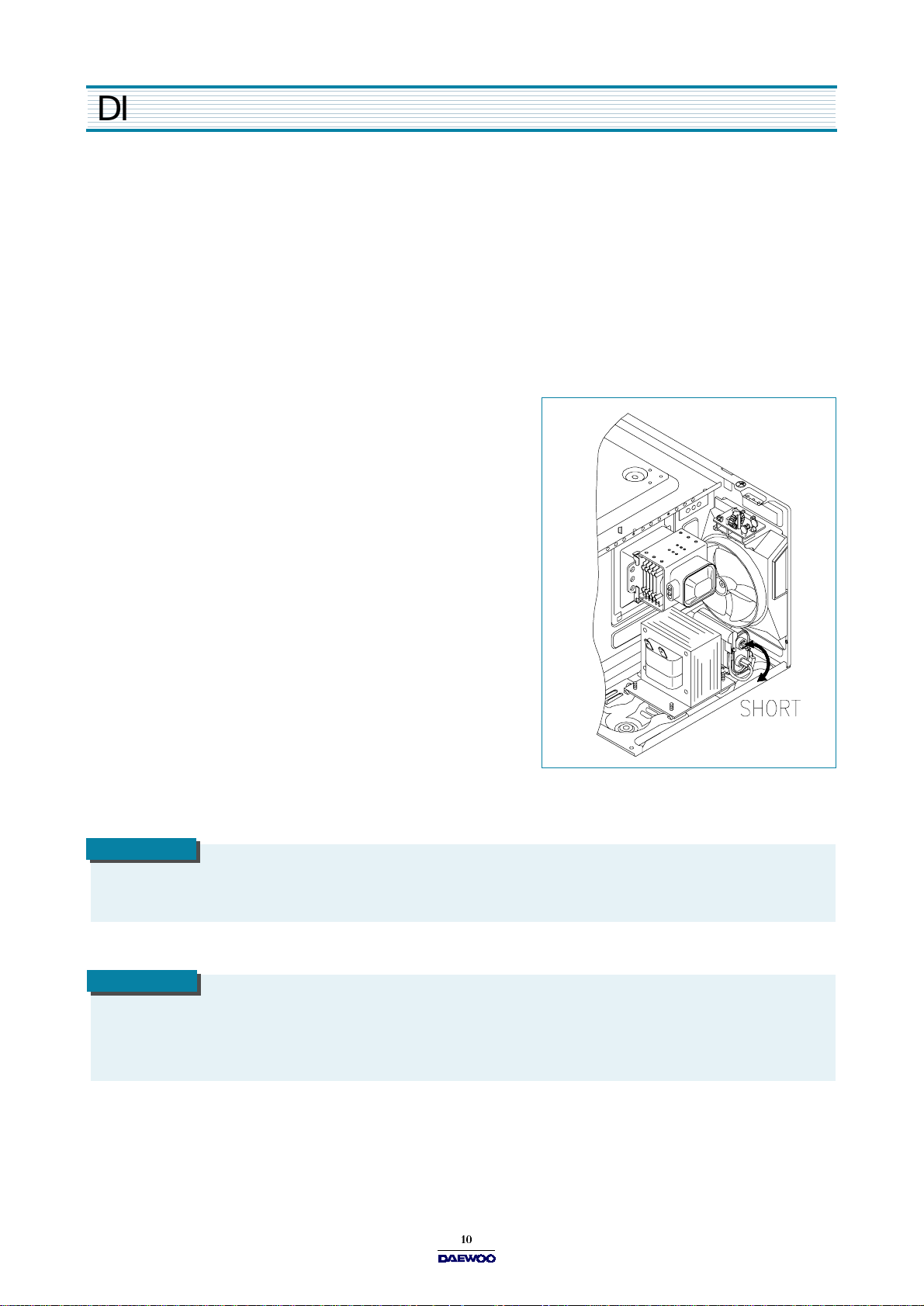
(2) Warning about the electric charge in the high voltage capacitor.
For about 30 seconds after the operation stopped and electric
charge remains in the high voltage capacitor. When replacing
or checking parts, short between oven chassis and the negative
high terminal of the high voltage capacitor, by using a properly
insulated screwdriver to discharge.
4. When the 12A fuse is blown out due to the operation of the monitor
switch; replace primary interlock switch, secondary interlock switch
and interlock monitor switch.
5. After repair or replacement of parts, make sure that the screws are
properly tightened, and all electrical connections are tightened.
6. Do not operate without cabinet.
CAUTION
WARNING
Service personnel should remove their watches whenever working close to or replacing the m agnetron.
W hen servicing the appliance, need a care of touching or replacing high potential parts because of electrical shock or
exposing microwave. These parts are as follows - HV Transformer, M agnetron, HV Capacitor, HV Diode. H V Fuse.
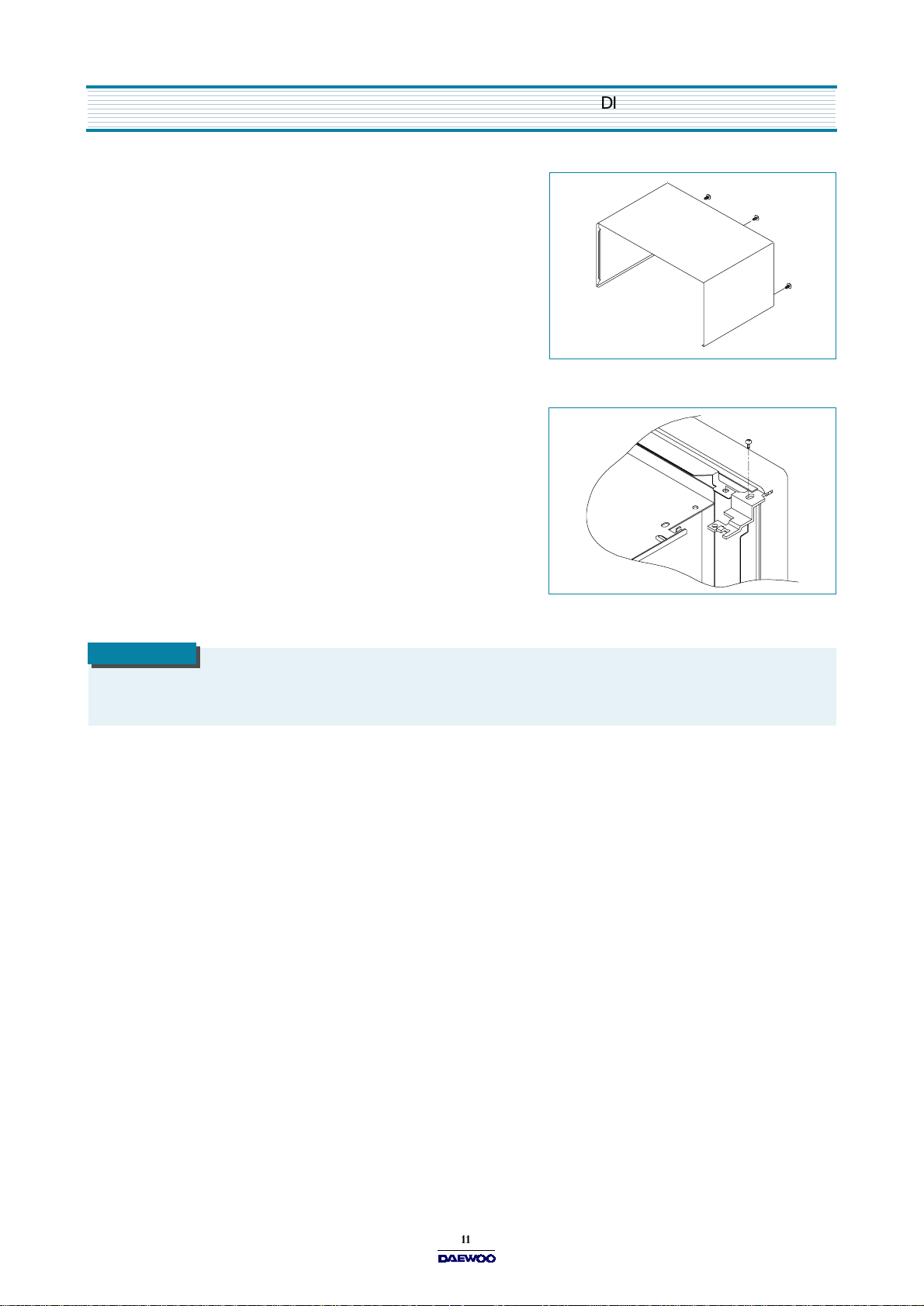
D ISASSEMBLY AND ASSEMBLY
1. To remove cabinet
1) Remove three screws on cabinet back.
2) Push the cabinet backward.
2. To remove door assembly
1) Remove a screw which secure the stopper hinge top.
2) Remove the door assembly from top plate of cavity.
3) Reverse the above for reassembly.
NOTE
After replacing the door assembly, perform a check of correct alignment with the hinge and cavity front plate.
Loading...