


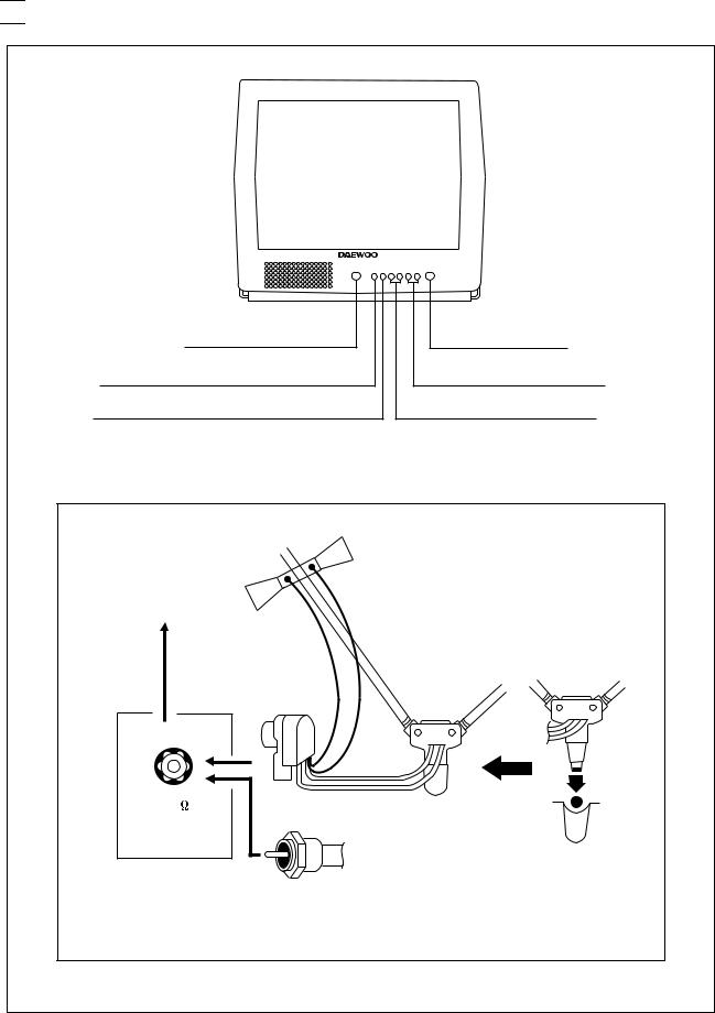

 CONTROL VIEW
REMOCON SENSOR |
POWER ON/OFF |
ENTER |
CH UP/DN |
MENU |
VOL UP/DN |
F-CONNECTOR |
|
300 OHM-75 OHM |
|
COUPLING |
|
TRANSFORMER |
|
VHF |
|
75 |
|
|
FROM 75 OHM |
|
VHF ANTENNA WITH |
|
CABLE OR CABLE |
|
TV SYSTEM |
|
3 |

 IMPORTANT SERVICE NOTES
1. X-RAY RADIATION PRECAUTION
1)Excessive high voltage can produce potentially hazardous X-RAY RADIATION. To avoid such hazards, the high voltage must not be above the specified limit. The nominal value of the high voltage of this receiver is 24.4kv(28.6kv) at zero beam current
*(minimum brightness) under a 120V AC power source. The high voltage must not, under any circumstances, exceed 25kv (29kv). Each time a receiver requires servicing, the high voltage should be checked following the HIGH VOLTAGE CHECK procedure on page 7 of this manual. It is recommended as a parts of the service record. It is important to use an accurate and reliable high voltage meter.
2)This receiver is equipped with X-RADIATION PROTECTION circuit which prevents the receiver from producing an excessively high voltage even if the B+voltage increases abnormally. Each time the receiver is serviced, X-RADIATION PROTECTION circuit must be checked to determine that the circuit is properly functioning, following the X-RADIATION PROTECTION CIRCUIT CHECK procedure on page 7 of this manual.
3)The only source of X-RAY RADIATION in this TV receiver is the picture tube. For continued X-RAY RADIATION protection, the replacement tube must be exactly the same type tube as specified in the parts list.
4)Some parts in this receiver have special safety-related characteristics for X-RAY RADIATION protection. For continued safety, parts replacement should be undertaken only after referring to the PRODUCT SAFETY NOTICE below.
2. SAFETY PRECAUTION
WARNING : Service should not be attempted by anyone unfamiliar with the necessary precautions on this receiver. The following are the necessary precautions to be observed before servicing.
1)Since the chassis of this receiver has hazardous potential to ground whenever the receiver is plugged in (floating chassis), an isolation transformer must be used during servicing to avoid shock hazard.
2)Always discharge the picture tube anode to the CRT conductive coating before handling the picture tube. The picture tube is highly evacuated and if broken, glass fragments will be violently expelled. Use shatterproof goggles and keep picture tube away from the body while handling.
3)When placing a chassis in the cabinet, always be certain that all the protective devices are put back in
place, such as; non-metallic control knobs, insulating covers, shields, isolation resistor-capacitor network, etc.
4)Before returning the set to the customer, always perform an AC leakage current check to the exposed metallic parts of the cabinet, such as antennas, terminals, screwheads, metal overlays, control shafts etc. to be sure the set is safe to operate without danger of electrical shock.
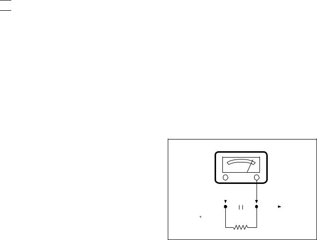
* Minimum brightness
Plug the AC line cord directly into a 120V AC outlet (do
not use a line isola-tion transformer during this check).
Use an AC voltmeter having 5000 ohms per volt or more sensitivity in the following manner.
Connect at 1500 ohm 10 watt resistor, paralleled by a 0.15 F. AC type capacitor, between a known good earth ground (water pipe, conduit etc.) and the exposed metallic parts, one at a time. Measure the AC voltage across the combination of 1500 ohm resistor and 0.15 F capacitor. Voltage measured must not exceed 0.3 volts RMS. This corresponds to 0.2 milliamp. AC. Any value exceeding this limit constitutes a potential shock hazard and must be corrected immediately.
AC VOLT METER
|
|
|
|
|
|
|
|
0.15 F |
|
|
|||
|
|
|
|
|
|
|
|
|
|
||||
|
|
|
|
|
|
|
|
|
|
|
|
|
|
|
|
|
|
|
|
|
|
|
|
|
|
|
|
|
|
|
|
|
|
|
|
|
|
|
Place this probe |
||
|
|
|
|
|
|
|
|
1500 ohm |
|||||
|
|
|
|
|
|
|
|
||||||
|
|
|
|
|
|
|
|
on each exposed |
|||||
Good earth ground |
10watt |
||||||||||||
|
|
||||||||||||
such as a water |
metalic part. |
|
|
pipe, conduit, etc. |
|
3. PRODUCT SAFETY NOTICE
Many electrical and mechanical parts in this chassis have special safety-related characteristics. These characteristics are often passed unnoticed by a visual inspection and the protection afforded by them cannot necessarily be obtained by using replacement components rated for higher voltage, wattage, etc. Replacement parts which have these special safety characteristics are identified in this manual and its supplements; electrical components having such features are identified by shading on the schematic diagram and the parts list.
Before replacing any of these components, read the parts list in this manual carefully. The use of substitute replacement parts which do not have the same safety characteristics as specified in the parts list may create X- ray radiation or other hazards.
4. SERVICE NOTES
1)When replacing parts or circuit boards, clamp or bend the lead wires to terminals before soldering.
2)When replacing a high wattage resistor (metal oxide film resistor) in the circuit board, keep the resistor min 1/2 inch away from circuit board.
3)Keep wires away from high voltage or high temperature components.
4
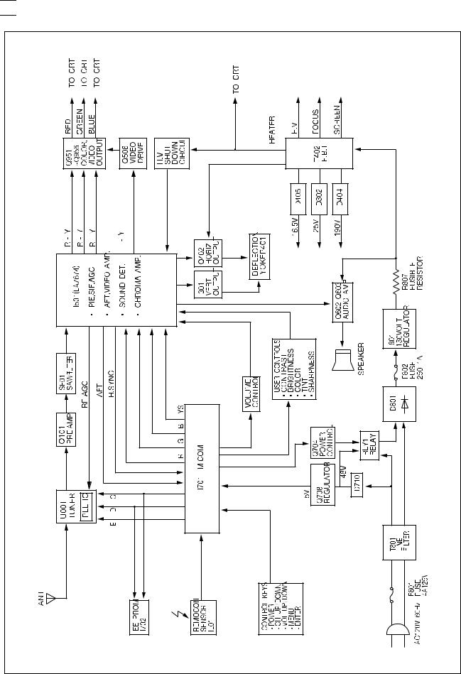

 BLOCK DIAGRAM
- 5 - |


 GENERAL ADJUSTMENTS
1. GENERAL
In the majority of cases, all color televisions will need only slight touch-up adjustment upon installation. Check the basic characteristics such as height, focus and subbright. Observe the picture for good black and white details without objectionable color shading. If color shading is evident, demagentize the receiver. If color shading still persists, perform purity and convergence adjustments. This should be all that is necessary to achieve Optimum receiver performance.
2. VERTICAL HEIGHT ADJUSTMENT
1)Tune in an active channel.
2)Adjust brightness and contrast controls for a good picture.
3)Adjust vertical height control (R315) for approximately one half inch over scan at top and bottom of picture screen.
4)Vertical centering adjustment VR316 Horizontal centering adjustment VR556.
3. FOCUS ADJUSTMENT
1)Tune in an active channel.
2)Adjust brightness, sharpness and contrast controls for a good picture.
3)Adjust focus control (part of T402) for sharp scanning lines and/or sharp picture.
4. RF AGC ADJUSTMENT
1)Tune in an active channel.
2)Using the attenuator, apply the signal of 60dBm to the antenna input terminal.
3)Turn RF AGC control (VR555) full clockwise until snow or/and noise appears in the picture, then slowly turn control counterclockwise until snow or/and noise disappears.
5. HIGH VOLTAGE CHECK
High voltage is not adjustable but must be checked to verify that the receiver is operating within safe and efficient design limitations as specified:
1)Operate Receiver for at least 15 minutes at 120V AC line.
2)Set brightness sharpness, contrast and color control to minumum position (Zero beam).
3)Connect accurate high voltage meter to CRT anode.
The reading should be 24.4kv(28.6kv)
(DTQ-14 ----- : 22.6kv ~ 24.6kv)
DTQ-20 ----- : 26.1kv ~ 28.8kv
If a correct reading cannot be obtained, check circuitry for malfunctioning components.
6. X-RADIATION PROTECTION C I R C U I T TEST
When service has been performed on the horizontal deflection system, high voltage system or B+ system, the X-RADIATION protection circuit must be tested for proper operation as follows:
1)Operate receiver for at least 15 minutes at 120V AC line.
2)Adjust all customer controls for normal picture and sound.
3)Check the voltage of D401 cathode. It's voltage should be about 22V DC.
4)Connect the cathode of diode D302 and D401 through a 2.7K ohm, 1/4W Resistor(R313).
5)To start operation, remove the resistor and touch the cathode of D401 to chassis ground with a short clip lead (Remove short clip lead as soon as the set operates again with normal picture).
6)If the operation of horizontal osc. does not stop in step The circuit must be repaired, before the set is returned to the customer.
7. CRT GRAY SCALE ADJUSTMENT
1)Tune in an active channel.
2)Set the COLOR control to minimum.
3)Turn the SCREEN control (on T402 fully counterclockwise.)
4)Rotate the RED, GREEN and BLUE BIAS controls (R971, R972, R973) counterclock wise from the maximum, set them to the position where notches in the knobs become parallel to the surface of P.C. Board.
5)Set the GREEN and BLUE DRIVE controls (R975, R974) to the mid position.
6)Turn the service switch SW20 (Service Position) on the CRT board.
7)Rotate the SCREEN control (on T402) gradually clockwise until the second horizontal line following the first line appears slightly on the screen. Then turn fully counterclockwise the two BIAS controls corresponding to the colors of the first and the second horizontal lines to eliminated the lines.
8)Set the SCREEN control to the position where the third horizontal line lights slightly on the screen.
9)Adjust the two BIAS control set to the minimum in item 7) above to obtain the slightly lighted horizontal line in the same levels of three (red, green, blue) colors. (The line should be white if the BIAS controls are adjusted properly.)
10)Turn the service switch SW20 again (Normal position on the CRT board.)
11)Press PICTURE-SEL, P-UP and set the brightness and contrast controls to the maximum.
12)Adjust the BLUE and GREEN DRIVE control to obtain proper white-blanced picture in high light areas.
13)Using P-SEL, P-DN key, set the brightness and contrast controls to obtain dark gray raster. Then check the white balance in low brightness. If the white balance is not proper, retouch the BIAS controls and DRIVE controls to obtain a good white balance in both low and high light areas.
7
8. SUB-BRIGHTNESS ADJUSTMENT
1)Tune in a color program.
2)Set the CONTRAST control to maximum and the BRIGHTNESS control to maximum and the SHARPNESS control to the center position.
3)Set the COLOR and TINT controls to center.
4)Set the SUB-BRIGHT control R554 to center and leave the receiver on five minutes in this state.
5)Watching the picture carefully, adjust the SUB-BRIGHT control in the position where the picture does not show evidence of blooming in high brightness area and not appear too dark in low bright area.
6)Check for BRIGHTNESS controls at both extremes.
7)If the picture does not appear dark with the CONTRAST and BRIGHTNESS control turned to minimum, or not appear bright with the controls turned to maximum, adjust the SUB-BRIGHT control again for an acceptable picture.
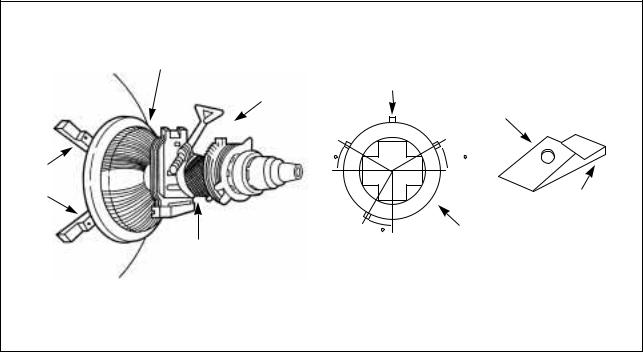
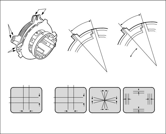
9.CONVERGENCE MAGNET ASSEMBLY POSITIONING
If Convergence magnet assembly and rubber wedges need mechanical positioning follow figure 2.
9-1. COLOR PURITY ADJUSTMENT
NOTE : Before attempting any purity adjustments, the receiver should be operated for at least 15 minutes.
1)Demagnetize the picture tube with a degaussing coil.
2)Adjust the CONTRAST and BRIGHTNESS controls to maximum
3)Adjust RED and BLUE Bias controls (R971 and R973) to provide only a green raster. Adjust the GREEN BIAS control (R972) if necessary.
4)Loosen the clamp screw holding the yoke, and slide the yoke backward to provide vertical green belt(zone)in the picture screen.
5)Remove the Rubber Wedges.
6)Rotate and spread the tabs of the purity magnet (See figure 2) around the neck of the picture tube until the green belt is in the center of the screen. At the same time, center the raster vertically.
7)Move the yoke slowly forward until a uniform green screen is obtained. Tighten the clamp screw of the yoke temporarily.
8)Check the purity of the red and blue raster by adjusting the BIAS controls.
9)Obtain a white raster, referring to  CRT GRAY SCALE ADJUSTMENT
 .
.
10)Proceed with covergence adjustment.
|
DEFLECTION |
|
|
|
YOKE |
TEMPORARY |
|
|
CONVERGENCE |
|
|
|
MOUNTING |
|
|
|
MAGNET ASS'Y |
|
RUBBER |
|
|
|
WEDGES |
|
{ |
|
|
|
30 |
|
30 |
RUBBER |
|
|
|
WEDGES |
|
|
ADHESIVE |
|
|
|
|
|
|
30 |
DEF. |
|
GLASS CLOTH |
|
YOKE |
|
|
|
|
PICTURE TUBE |
TAPE |
|
|
|
|
|
Fig. 2 Rubber Wedges Location
8
9-2. CONVERGENCE ADJUSTMENTS
NOTE : Before attempting any purity adjustments, the receiver should be operated for at least 15 minutes.
A. CENTER CONVERGENCE ADJUSTMENT
1)Receive crosshatch pattern with a crosshatch signal generator.
2)Adjust the BRIGHTNESS and CONTRAST Controls for a good picture.
3)Adjust two tabs of the 4-Pole Magnets to change the angle between them (See Fig. 3) and superimpose red and blue vertical lines in the center area of the picture screen. (See Fig. 4)
4)Turn both tabs at the same time keeping their angles constant to superimpose red and blue horizontal lines at the center of the screen. (See Fig. 4)
5)Adjust two tabs of 6-Pole Magnets to superimpose red/blue line with green on top of each other. Adjusting the angle affects the vertical lines and rotating both magnets affects the horizontal lines.
6)Repeat adjustments 3), 4), 5) keeping in mind red, green and blue movement, because 4-Pole Magnets and 6-Pole Magnets interact and make dot movement complex.
B. CIRCUMFERENCE CONVERGENCE ADJUSTMENT
NOTE : This adjustment requires Rubber Wedge Kit.
1)Loosen the clamping screw on deflection yoke to allow the yoke to tilt.
2)Place a wedge as shown in figure 2 temporarily. (Do not remove cover paper on adhesive part of the wedge.)
3)Tilt front of the deflection yoke up or down to obtain better convergence in circumference. (See Fig. 4) Push the mounting wedge into the space between picture and the yoke to hold the yoke temporarily.
4)Place other wedge into bottom space and remove the cover paper to stick.
5)Tilt front of the yoke right or left to obtain better convergence in cicumference. (See Fig. 4)
6)Hold the yoke position and put another wedge in either upper space. Remove cover paper and stick the wedge on picture tube to hold the yoke.
7)Detach the temporarily mounted wedge and put it in another upper space. Stick it on picture tube to fix the yoke.
8)After placing three wedges, re-check overall convergence. Tighten the screw firmly to hold the yoke tightly in place.
9)Stick 3 adhesive tapes on wedges as shown in figur3,2.
|
4-POLE |
|
MAGNETS |
|
ADJUST THE |
PURITY |
ANGLE |
(VERTICAL |
|
MAGNETS |
LINES) |
6-POLE MAGNETS
CONVERGENCE MAGNET ASSEMBLY
Fig. 3
BLUE RED |
RED/BLUE |
GRN |
|
|
|
|
B |
G |
R |
BLUE |
RED/BLUE |
R |
|
|
RED |
GRN |
G |
|
|
B |
|
|
||
|
|
|
|
|
|
|
R |
G |
B |
CONSTANT
ROTATE TWO TABS AT THE SAME TIME (HORIZONTAL LINES)
ADJUSTMENT OF MAGNET
B 
G B G R
R
B
G
R
B G R  R
R
G
B
4-Pole Magnets Movement |
6-Pole Magnets Movement |
Incline the Yoke up(or down) Incline the Yoke right(or left) |
Center Convergence by Convergence Magnets |
Circumference Convergence by DEF. Yoke |
|
Fig. 4 Dot Movement Pattern
9
10. PICTURE IF/AFT ADJUSTMENTS
NOTE : THIS RECEIVER IS TRANSISTORIZED AND SPECIAL CARE MUST BE TAKEN WHEN SERVICING. READ THE FOLLOWING (NOTES BEFORE ATTEMPTING ALIGNMENT)
 Alignment requires an exacting procedure and should be undertaken only when necessary.
 Isolation transformer must be used to prevent shock hazard.
 The test equipment specified or its equivalent is required to perform the alignment properly. Use of equipment which does not meet these requirements may result in improper alignment.
 Accurate equipment is essential to obtain proper alignment of this receiver.
 Use of excessive signal from a sweep generator can cause overloading of receiver circuit Overloading should be avoided to obtain a true response curve. Insertion of markers from the marker generator should not cause distortion of the response curve.
 The AC Power line voltage should be kept 120 volts while alignment is being performed.
  Do not attempt to disconnect any components while the receiver is in operation.
Make sure the power cord is disconnected before replacing any parts in the receiver.
TEST EQUIPMENT
Digital voltmeter 


 National Model VP-2600A or equivalent
Oscilloscope 


 Tektronix Model 2215A or equivalent.
Direct/Low-capacity probe 


 Tektronix Model P6120 or equivalent (Accessory of oscilloscope)
Color-Bar/Dot/Crosshatch generator 


 Tektronix Model 146 or equivalent.
PIF sweep marker generator 


 Nihon Tsushinki Model 4723 or equivalent
Power supply 


 Academy Model 150A or equivalent
Isolation transformer 


 Voltage adjustable type having capacity of at least 150 watts
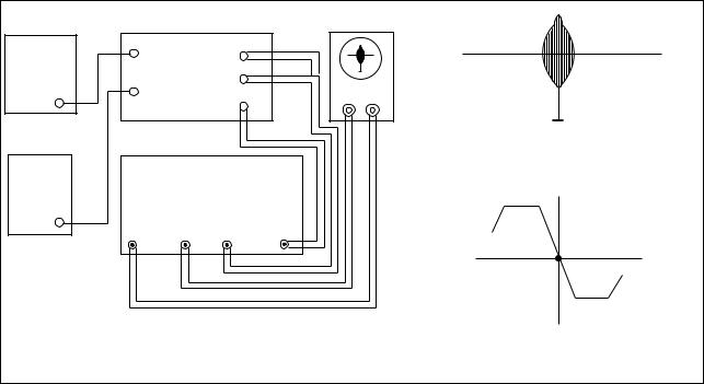
BLOCK DIAGRAM
B+ |
|
MAIN BOARD |
OSCILLOSCOPE |
|
|||
|
|
|
|
|
|
||
BIAS |
|
TP3 |
TP6 |
|
|
|
|
POWER |
|
|
|
|
|||
|
|
|
|
|
|
||
SUPPLY |
|
|
TP1 |
|
|
|
|
A |
|
TP5 |
|
Y |
|
||
|
|
X |
|
||||
(16.5V) |
|
TP4 |
|
||||
|
|
|
|
|
|||
|
|
|
|
|
|
||
AGC |
|
|
|
|
|
45.75MHz |
|
|
|
|
|
Fig. 6 |
PIF Response |
||
BIAS |
PIF SWEEP/MARKER GEN. |
||||||
|
|
||||||
POWER |
|
|
|||||
|
|
|
|
|
|
||
SUPPLY |
|
|
|
|
|
|
|
B |
|
|
|
|
|
|
|
(4-5V) |
V |
H |
DET IN |
OUT |
|
|
|
|
|
|
|||||
|
|
|
|
|
|
P 45.75MHz |
|
|
Fig. 5 Picture IF Sweep Alignment |
Fig. 7 |
AFT Response Curve |
||||
1)Disconnect the  TUNER IF
 output from TP1 and connect equipment as shown above.
2)Set the sweep/marker generator for 30 Vrms.
3)Observe 1 Vp-p on scope by adjusting power supply B (4~5V).
4)Adjust PIF coil L505 for according beat signal with 45.75 MHz marker on scope (See Fig. 6).
5)Connect the  DET IN
 to TP6.
6)Adjust AFT coil L504 for center display at 45.75 MHz on scope (See Fig. 7).
7)After completing the above steps, disconnect equipment and adjust the AGC delay circuit as explained in the General Adjustments section of this manual.
10


 TROUBLE SHOOTING CHARTS
|
NO POWER |
|
|
|
|
|
|
|
|
DOES RLY1 (RELAY) OPERATE? |
YES |
|
GO TO |
A |
|||
|
|
|
|
|
|
|||
|
|
|
|
|
NO |
|
GO TO |
B |
|
|
|
|
|
|
|
||
A |
|
|
|
|
|
|
|
|
|
|
|
|
CHECK |
|
|
|
|
|
CHECK |
|
|
#30 |
|
|
|
|
|
|
|
(7.5V DC) |
|
|
|
||
|
IN/OUT VOLTAGES |
|
|
|
|
|
||
|
|
R413 18K |
|
|
|
|
|
|
|
OF I801(130VOLT REG) |
|
|
|
|
|
||
|
IN: 150VDC |
|
2WATT |
30 |
|
|
DOES |
|
|
OUT: 130VDC |
|
|
|
|
SHUT DOWN |
||
|
|
|
R414 20K |
|
|
|
CIRCUIT |
|
|
|
|
2WATT |
|
I501 |
|
OPERATE? |
|
|
|
|
|
|
|
|
||
|
|
|
|
|
|
|
|
|
RLY1 |
CHECK |
130VDC |
26 |
23 |
24 |
|
H.V |
|
RELAY |
I801 |
|
|
|
|
|
|
SHUT DOWN |
STR30130 |
|
|
|
|
|
|
OCCURS AT |
|
|
|
IF #26 NORMAL |
|
|
|
|
||
|
|
|
|
|
|
|
22VDC |
|
|
|
|
& NO OUTPUT AT |
|
|
|
||
|
|
|
|
|
|
|
||
|
|
|
#23 THEN |
|
Q402 |
|
|
|
|
|
|
CHANGE I501 |
|
H. OUTPUT |
|
CHECK |
|
|
|
|
|
|
|
|
|
Q402 |
|
|
|
|
|
|
|
|
COLLECTOR |
|
|
|
16.5V |
|
|
|
T402 |
|
|
|
|
D405 |
|
5 |
F.B.T |
|
|
|
|
|
|
|
|
|||
|
|
|
|
|
|
|
||
|
|
|
CHECK |
|
|
|
4 |
|
|
|
|
|
|
|
|
|
|
|
|
|
16.5V LINE |
|
|
|
|
|
|
|
|
|
|
|
|
|
CHECK |
B |
|
|
|
|
|
|
|
ALL THE POINTS |
|
|
|
|
|
|
|
THEN CHANGE |
|
|
|
|
NORMAL: 5V |
|
|
|
I701 |
|
|
|
Q701 |
RESET: 0V |
|
|
|
|
|
|
|
RESET |
|
|
|
|
|
|
|
SHOULD |
|
1 |
9 |
|
PWR |
|
|
|
BE |
|
I701 |
|
CONTROL |
|
||
|
4.3V-5.2V |
|
2 |
23 |
|
KEY |
|
|
5V |
|
|
|
|
|
|
|
|
|
Q708 |
|
|
|
OPEN LOAD |
|
KEY OPERATE? |
|
|
REGULATOR |
|
|
|
THEN CHECK |
|
||
|
|
|
|
|
CHECK DIODE |
|||
|
R759 |
|
|
|
#23 ON STATE |
|||
|
|
|
|
D701 & SWITCH |
||||
|
|
|
|
|
4 ~5V |
|
|
|
|
|
|
|
|
|
|
KEY BOARD |
|
|
|
|
|
|
|
|
|
|
|
CHECK |
|
|
|
|
|
|
|
|
F801 |
D710 |
|
Q704 |
|
|
|
|
|
125V 4A |
|
|
|
|
|
||
|
|
POWER |
|
|
|
|
||
|
CHECK |
|
|
|
|
|
|
|
|
|
|
CONTROL |
|
|
|
|
|
|
LEAD |
|
|
|
|
|
|
|
|
|
|
|
|
|
|
|
|
|
SOLDERING |
|
|
|
CHECK |
|
|
|
|
|
|
|
|
Q704 & |
|
|
|
|
L801 |
|
RLY1 |
RELAY |
|
|
||
|
LINE FILTER |
|
RELAY |
|
|
|
|
|
|
|
|
11 |
|
|
|
|
|

NO PICTURE
OK
CHECK THE WAVE FORM OF
I501 #44
NG
C |
|
|
|
|
|
|
|
|
|
COMPOSITE |
|
|
21 |
||
|
|
|
|
|
|||
|
|
VIDEO INPUT |
|
I501 |
|
||
|
|
|
|
H |
|
|
|
|
|
|
|
|
LA 7674 |
||
|
|
|
|
|
|
42 |
|
|
|
|
|
|
C217 |
|
|
|
CONTRAST |
|
|
|
|
39 |
|
CHECK |
BRIGHT |
|
|
|
|
|
|
CONTROL |
|
|
|
|
31 |
|
|
|
|
|
|
|
|
||
(MAX) |
|
|
|
|
|
11 |
14 |
VOLTAGES |
|
|
|
|
|
||
|
|
|
|
|
|
|
|
#39:7.5V |
Q501 |
R554 |
|
|
|
|
|
#31:6.2V |
|
|
CHECK |
|
|
||
ABL |
SUB-BRIGHT |
|
|
||||
|
9V LINES |
|
|||||
|
|
|
|
|
|
||
|
|
|
|
|
#11,14 |
|
|
|
|
|
|
|
|
C410 |
|
|
|
|
|
|
CHECK |
0.1 (M) |
|
|
|
|
|
|
C410 |
|
|
D |
|
|
|
|
PIN 4 |
|
|
|
|
|
AGC |
|
|
||
|
|
|
|
|
|
||
ENA |
16 |
4 |
|
7 |
12V |
|
|
|
|
|
|
||||
DATA |
|
|
|
|
|||
15 |
U001 TUNER |
|
VT (33V) |
|
|
||
CLK |
|
|
|
||||
14 |
|
|
9 |
|
|
||
8 |
10 |
|
|
|
|||
|
|
|
|
||||
|
|
|
|
|
|||
GO TO |
C |
GO TO |
D |
H |
|
Y-OUT |
Q506 |
|
||
VIDEO |
||||
|
|
|||
|
|
DRIVE |
||
|
|
|
CHECK |
|
|
|
|
190V |
|
|
H. BLANKING |
LINE |
||
|
|
|||
|
3 |
|
|
|
T402 |
D404 |
|
||
FBT |
|
|
||
7 |
10 |
|
|
|
|
|
|
R402 |
|
CHECK
HEATER
VTG 6.3Vrms
IF |
5V |
|
I701 |
|
Q101 |
|
ADJUST |
|
|
|
|
|
|
|||
41 |
42 |
PRE-AMP |
|
RF-AGC |
|
|
|
|
R555 |
DETECTOR |
|
||
|
|
|
|
|
|
|
|
|
|
|
|
OUTPUT |
|
|
|
SF01 |
8 |
|
10 |
|
|
|
SAW FILTER |
9 |
I501 |
44 |
TO Q504 |
|
|
|
||||
|
|
|
|
|||
CHECK |
CHECK THE |
|
|
LA7674 |
|
|
|
|
2 |
11 14 |
|
||
CRYSTAL |
VOLTAGE |
CHECK |
|
|
||
|
|
|
|
|||
X701 |
AT Q101 |
IF AGC |
|
|
|
H |
|
|
VTG. |
|
|
|
|
5VDC
CHECK
9V LINE #11, 14
12
|
NO SOUND |
|
|
|
|
|
|
|
|
|
|
YES |
|
GO TO |
E |
|
CHECK FOR SIGNAL |
|
|
|
|
||
|
AT I501 #6 |
|
|
|
|
|
|
|
|
|
|
NO |
|
GO TO |
F |
|
|
|
|
|
|
||
E |
|
|
|
IF #4 IS OK |
|
|
|
|
|
|
& NO OUTPUT |
|
|
||
|
|
|
|
|
|
||
|
I501 |
4 |
|
THEN |
|
|
|
|
|
CHANGE I501 |
|
|
|||
|
LA7674 |
|
|
|
|
|
|
|
|
|
|
|
|
CHECK |
|
|
|
|
Q601 |
|
|
CONNECTOR |
|
|
|
6 |
|
|
P601 |
|
|
|
|
AUDIO |
|
|
|
||
|
|
|
|
|
|
||
|
48 |
|
AMP |
|
|
|
|
|
|
|
|
|
|
|
|
SOUND VOLUME |
|
|
Q602,Q603 |
T601 |
SP01 |
|
|
|
|
AUDIO |
|
||||
MAX: ~7VDC |
|
|
TSP1036 |
SPEAKER |
|||
|
|
OUT |
|||||
MIN: ~1VDC |
|
|
|
|
|
||
|
|
|
|
|
|
||
VOL-UP |
I701 |
30 |
|
|
|
|
|
DOWN |
LOW PASS |
CHECK |
|
|
|
||
CONTROL |
|
FILTER |
|
|
|
||
KEY |
|
|
|
R601 & |
|
|
|
|
|
|
|
123V LINE |
|
|
|
|
|
|
DISCONNECT LOAD |
|
|
|
|
|
|
|
CHECK FOR SND, |
|
|
|
|
|
|
|
PWM SIGNAL, IF |
|
|
|
|
|
|
|
MISSING REPLACE |
|
|
|
|
|
|
|
I701 |
|
|
|
|
F |
|
|
|
|
|
|
|
|
CHECK |
|
1 |
DE EMPHASIS |
|
|
|
|
9VDC |
11 |
|
|
|
||
|
|
|
|
|
|||
|
LINE#11,14 |
14 |
|
|
|
|
|
|
|
|
|
|
|
|
|
|
SOUND TAKEOFF |
44 |
I501 |
X601 |
|
|
|
|
|
|
LA7674 |
|
|
|
|
|
NO OUTPUT: |
|
4 |
|
|
|
|
|
CHANGE I501 |
|
|
|
|
|
|
|
|
48 |
|
|
|
|
|
|
|
Z601 |
SOUND |
CHECK |
|
|
|
|
|
|
IF INPUT |
|
|
|
|
|
|
|
FM DET. |
|
|
|
|
|
|
|
|
|
|
|
|
|
|
|
|
CIRCUIT |
|
|
|
|
|
|
13 |
|
|
|
|
 Loading...