


ma5000vz
Model: Macro-Tech 5000VZ
Some models may be exported under the name Amcron.
©2003 by Crown Audio, Inc., P.O. Box 1000, Elkhart, IN 46515-1000 U.S.A. Telephone: 574-294-8000.
Fax: 574-294-8329. Trademark Notice:
Amcron, Crown, Macro-Tech, IOC, ODEP, IQ System
International, Inc. Other trademarks are the property of their respective owners.
Approved for
THX Theatre
Systems
PIP, SmartAmp
and
and
Grounded Bridge
P.I.P.
are registered trademarks of Crown
®
are trademarks and
103169-2A
3/03

3
YEAR
THREE YEAR
FULL WARRANTY
3
YEAR
WORLDWIDE
The Crown Audio Division of Crown International, Inc., 1718 West
Mishawaka Road, Elkhart, Indiana 46517-4095 U.S.A. warrants to you,
the ORIGINAL PURCHASER and ANY SUBSEQUENT OWNER of each
NEW Crown
purchase by the original purchaser (the “warranty period”) that the new
Crown product is free of defects in materials and workmanship, and we
further warrant the new Crown product regardless of the reason for
failure, except as excluded in this Crown Warranty.
1
Note: If your unit bears the name “Amcron,” please substitute it for the
name “Crown” in this warranty.
ITEMS EXCLUDED FROM THIS CROWN WARRANTY
This Crown Warranty is in effect only for failure of a new Crown product
which occurred within the Warranty Period. It does not cover any product
which has been damaged because of any intentional misuse, accident,
negligence, or loss which is covered under any of your insurance
contracts. This Crown Warranty also does not extend to the new Crown
product if the serial number has been defaced, altered, or removed.
We will remedy any defect, regardless of the reason for failure (except
as excluded), by repair, replacement, or refund. We may not elect refund
unless you agree, or unless we are unable to provide replacement, and
repair is not practical or cannot be timely made. If a refund is elected, then
you must make the defective or malfunctioning product available to us
free and clear of all liens or other encumbrances. The refund will be equal
to the actual purchase price, not including interest, insurance, closing
costs, and other finance charges less a reasonable depreciation on the
product from the date of original purchase. Warranty work can only be
performed at our authorized service centers. We will remedy the defect
and ship the product from the service center within a reasonable time
after receipt of the defective product at our authorized service center.
You must notify us of your need for warranty service not later than ninety
(90) days after expiration of the warranty period. All components must be
shipped in a factory pack. Corrective action will be taken within a
reasonable time of the date of receipt of the defective product by our
authorized service center. If the repairs made by our authorized service
center are not satisfactory, notify our authorized service center
immediately.
DISCLAIMER OF CONSEQUENTIAL AND INCIDENTAL DAMAGES
YOU ARE NOT ENTITLED TO RECOVER FROM US ANY INCIDENTAL
DAMAGES RESULTING FROM ANY DEFECT IN THE NEW CROWN
PRODUCT. THIS INCLUDES ANY DAMAGE TO ANOTHER PRODUCT
OR PRODUCTS RESULTING FROM SUCH A DEFECT.
No person has the authority to enlarge, amend, or modify this Crown
Warranty. This Crown Warranty is not extended by the length of time
which you are deprived of the use of the new Crown product. Repairs and
replacement parts provided under the terms of this Crown Warranty shall
carry only the unexpired portion of this Crown Warranty.
We reserve the right to change the design of any product from time to time
without notice and with no obligation to make corresponding changes in
products previously manufactured.
No action to enforce this Crown Warranty shall be commenced later than
ninety (90) days after expiration of the warranty period.
THIS STATEMENT OF WARRANTY SUPERSEDES ANY OTHERS
CONTAINED IN THIS MANUAL FOR CROWN PRODUCTS.
Telephone: 219-294-8200. Facsimile: 219-294-8301
SUMMARY OF WARRANTY
1
product, for a period of three (3) years from the date of
WHAT THE WARRANTOR WILL DO
HOW TO OBTAIN WARRANTY SERVICE
WARRANTY ALTERATIONS
DESIGN CHANGES
LEGAL REMEDIES OF PURCHASER
9/90
NORTH AMERICA
The Crown Audio Division of Crown International, Inc., 1718 West Mishawaka
Road, Elkhart, Indiana 46517-4095 U.S.A. warrants to you, the ORIGINAL
PURCHASER and ANY SUBSEQUENT OWNER of each NEW Crown product, for a period of three (3) years from the date of purchase by the original
purchaser (the “warranty period”) that the new Crown product is free of defects
in materials and workmanship. We further warrant the new Crown product
regardless of the reason for failure, except as excluded in this Warranty.
ITEMS EXCLUDED FROM THIS CROWN WARRANTY
This Crown Warranty is in effect only for failure of a new Crown product which
occurred within the Warranty Period. It does not cover any product which has
been damaged because of any intentional misuse, accident, negligence, or
loss which is covered under any of your insurance contracts. This Crown
Warranty also does not extend to the new Crown product if the serial number
has been defaced, altered, or removed.
We will remedy any defect, regardless of the reason for failure (except as
excluded), by repair, replacement, or refund. We may not elect refund unless
you agree, or unless we are unable to provide replacement, and repair is not
practical or cannot be timely made. If a refund is elected, then you must make
the defective or malfunctioning product available to us free and clear of all liens
or other encumbrances. The refund will be equal to the actual purchase price,
not including interest, insurance, closing costs, and other finance charges less
a reasonable depreciation on the product from the date of original purchase.
Warranty work can only be performed at our authorized service centers or at
the factory. We will remedy the defect and ship the product from the service
center or our factory within a reasonable time after receipt of the defective
product at our authorized service center or our factory. All expenses in
remedying the defect, including surface shipping costs in the United States,
will be borne by us. (You must bear the expense of shipping the product
between any foreign country and the port of entry in the United States and all
taxes, duties, and other customs fees for such foreign shipments.)
You must notify us of your need for warranty service not later than ninety (90)
days after expiration of the warranty period. All components must be shipped
in a factory pack, which, if needed, may be obtained from us free of charge.
Corrective action will be taken within a reasonable time of the date of receipt
of the defective product by us or our authorized service center. If the repairs
made by us or our authorized service center are not satisfactory, notify us or
our authorized service center immediately.
DISCLAIMER OF CONSEQUENTIAL AND INCIDENTAL DAMAGES
YOU ARE NOT ENTITLED TO RECOVER FROM US ANY INCIDENTAL
DAMAGES RESULTING FROM ANY DEFECT IN THE NEW CROWN
PRODUCT. THIS INCLUDES ANY DAMAGE TO ANOTHER PRODUCT OR
PRODUCTS RESULTING FROM SUCH A DEFECT. SOME STATES DO
NOT ALLOW THE EXCLUSION OR LIMITATIONS OF INCIDENTAL OR
CONSEQUENTIAL DAMAGES, SO THE ABOVE LIMITATION OR
EXCLUSION MAY NOT APPLY TO YOU.
No person has the authority to enlarge, amend, or modify this Crown Warranty.
This Crown Warranty is not extended by the length of time which you are
deprived of the use of the new Crown product. Repairs and replacement parts
provided under the terms of this Crown Warranty shall carry only the unexpired
portion of this Crown Warranty.
We reserve the right to change the design of any product from time to time
without notice and with no obligation to make corresponding changes in
products previously manufactured.
THIS CROWN WARRANTY GIVES YOU SPECIFIC LEGAL RIGHTS, YOU
MAY ALSO HAVE OTHER RIGHTS WHICH VARY FROM STATE TO STATE.
No action to enforce this Crown Warranty shall be commenced later than
ninety (90) days after expiration of the warranty period.
THIS STATEMENT OF WARRANTY SUPERSEDES ANY OTHERS
CONTAINED IN THIS MANUAL FOR CROWN PRODUCTS.
Telephone: 219-294-8200. Facsimile: 219-294-8301
SUMMARY OF WARRANTY
WHAT THE WARRANTOR WILL DO
HOW TO OBTAIN WARRANTY SERVICE
WARRANTY ALTERATIONS
DESIGN CHANGES
LEGAL REMEDIES OF PURCHASER
9/90

Macro-Tech 5000VZ Power Amplifier
Important Safety Instructions
1) Read these instructions.
2) Keep these instructions.
3) Heed all warnings.
4) Follow all instructions.
5) Do not use this apparatus near water.
6) Clean only with a dry cloth.
7) Do not block any ventilation openings. Install in accordance with the
manufacturer’s instructions.
8) Do not install near any heat sources such as radiators, heat registers, stoves,
or other apparatus that produce heat.
9) Do not defeat the safety purpose of the polarized or grounding-type plug. A
polarized plug has two blades with one wider than the other. A groundingtype plug has two blades and a third grounding prong. The wide blade or the
third prong is provided for your safety. If the provided plug does not fit into
your outlet, consult an electrician for replacement of the obsolete outlet.
10) Protect the power cord from being walked on or pinched, particularly at
plugs, convenience receptacles, and the point where they exit from the apparatus.
11) Only use attachments/accessories specified by the manufacturer.
12) Unplug this apparatus during lightning storms or when unused for long periods of time.
13) Refer all servicing to qualified service personnel. Servicing is required when
the apparatus has been damaged in any way, such as power-supply cord or
plug is damaged, liquid has been spilled or objects have fallen into the apparatus, the apparatus has been exposed to rain or moisture, does not operate
normally, or has been dropped.
Reference Manual
Page 3
The information furnished in this manual does not include all of the details of design, production, or variations of
the equipment. Nor does it cover every possible situation which may arise during installation, operation or maintenance. If your unit bears the name “Amcron,” please substitute it for the name “Crown” in this manual. If you need
special assistance beyond the scope of this manual, please contact our Technical Support Group.
Crown Technical Support Group
1718 W. Mishawaka Rd., Elkhart, Indiana 46517 U.S.A.
Phone: 800-342-6939 (North America, Puerto Rico and Virgin Islands) or 574-294-8200
Fax: 574-294-8301 Fax Back (North America only): 800-294-4094 or 574-293-9200
Fax Back (International): 574-294-8100 Internet: http://www.crownaudio.com
DANGER: This amplifier can produce lethal levels of
output power! Be very careful when making connections. Do
The lightning bolt
triangle is used to
alert the user to the
risk of electric shock.
not attempt to change the output wiring unless AC power has
been removed from the amplifier for at least 10 seconds.
WARNING: This unit is capable of producing very high
sound pressure levels. Continuous exposure to high sound
The exclamation
point triangle is used
to alert the user to
important operating
or maintenance
instructions.
pressure levels can cause permanent hearing impairment or
loss. Caution is advised and ear protection recommended
when playing at high volumes.
C A U T I O N
RISK OF ELECTRIC SHOCK
DO NOT OPEN
TO PREVENT ELECTRIC SHOCK DO
NOT REMOVE TOP OR BOTTOM
COVERS. NO USER SERVICEABLE
PARTS INSIDE. REFER SERVICING
TO QUALIFIED SERVICE PERSONNEL. DISCONNECT POWER CORD
BEFORE REMOVING REAR INPUT
MODULE TO ACCESS GAIN SWITCH.
WARNING
TO REDUCE THE RISK OF ELECTRIC
SHOCK, DO NOT EXPOSE THIS
EQUIPMENT TO RAIN OR MOISTURE!
A V I S
RISQUE DE CHOC ÉLECTRIQUE
N’OUVREZ PAS
À PRÉVENIR LE CHOC ÉLECTRIQUE
N’ENLEVEZ PAS LES COUVERCLES.
IL N’Y A PAS DES PARTIES
SERVICEABLE À L’INTÉRIEUR. TOUS
REPARATIONS DOIT ETRE FAIRE PAR
PERSONNEL QUALIFIÉ SEULMENT.
DÉBRANCHER LA BORNE AVANT
D’OUVRIR LA MODULE EN ARRIÈRE.
Magnetic Field
CAUTION! Do not locate sensitive high-gain equipment such as preamplifiers or tape decks directly
above or below the unit. Because this amplifier has
a high power density, it has a strong magnetic field
which can induce hum into unshielded devices that
are located nearby. The field is strongest just above
and below the unit.
If an equipment rack is used, we recommend locating
the amplifier(s) in the bottom of the rack and the
preamplifier or other sensitive equipment at the top.

Macro-Tech 5000VZ Power Amplifier
CONTENTS
1 Welcome ................................................................................. 8
1.1 Why So Much Power? ....................................................... 8
1.2 Unpacking ........................................................................ 8
1.3 Features ........................................................................... 9
2 Facilities ................................................................................10
3 Installation ............................................................................ 13
3.1 Mounting ........................................................................ 13
3.2 Cooling ........................................................................... 13
3.3 Wiring ............................................................................ 14
3.3.1 Stereo (Two-Channel) Operation .......................... 14
3.3.2 Bridge-Mono Operation ....................................... 15
3.3.3 Parallel-Mono Operation ...................................... 16
3.3.4 Input Connection ................................................. 17
3.3.5 Output Connection .............................................. 18
3.3.6 Additional Load Protection ................................... 20
3.4 AC Mains Power Requirements ...................................... 21
4 Operation .............................................................................. 22
4.1 Precautions..................................................................... 22
4.2 Indicators ....................................................................... 22
4.3 Protection Systems ......................................................... 24
ODEP ..................................................................
4.3.1
4.3.2 Standby ............................................................... 24
4.3.3 Transformer Thermal Protection ........................... 25
4.3.4 Power Supply Fuses ............................................ 25
4.4 Controls .......................................................................... 26
4.5 Filter Cleaning ................................................................ 27
5 Technical Information........................................................... 28
5.1 Overview ........................................................................ 28
5.2 VZ Power ........................................................................ 28
5.2.1 Background......................................................... 28
5.2.2 The VZ Supply ..................................................... 29
5.3 Circuit Theory ................................................................. 29
5.3.1 Stereo Operation ................................................. 29
5.3.2 Bridge-Mono Operation ....................................... 32
5.3.3 Parallel-Mono Operation ...................................... 32
5.3.4 Terminator Module ............................................... 32
5.3.5. Display Module .................................................... 32
6 Specifications ....................................................................... 33
7 AC Power Draw and Thermal Dissipation ............................ 39
24
Page 6
8 Accessories .......................................................................... 40
PIP
8.1
8.2 Level Control Security Kit ................................................ 42
Modules ................................................................... 40
Reference Manual

Macro-Tech 5000VZ Power Amplifier
9 Service .................................................................................. 43
9.1 Worldwide Service .......................................................... 43
9.2 North American Service .................................................. 43
9.2.1 Service at a North American Service Center ........ 43
9.2.2 Factory Service.................................................... 43
1.1
Macro-Tech 5000VZ
2.1 Front Facilities ......................................................................... 10
2.2 Front Facilities behind the Filter Grille ...................................... 11
2.3 Rear Facilities .......................................................................... 12
2.4 International Output Binding Posts .......................................... 12
2.5 Output Cover .......................................................................... 12
3.1 Mounting Dimensions .............................................................. 13
3.2 Top View of a Rack-Mounted Unit ........................................... 13
3.3 Proper Air Flow in a Rack Cabinet ........................................... 13
3.4 Stereo Wiring ........................................................................... 14
3.5 Bridge-Mono Wiring ................................................................ 15
3.6 Parallel-Mono Wiring ............................................................... 16
3.7 Unbalanced Input Wiring ........................................................ 17
3.8 Balanced Input Wiring ............................................................. 17
3.9 Balanced and Unbalanced Phone Plug Wiring ....................... 17
3.10 Loudspeaker Offset Integration Switch ................................... 18
3.11 Input Ground Lift Switch .......................................................... 18
3.12 Wire Size Nomograph ............................................................. 19
3.13 Loudspeaker Fuse Nomograph .............................................. 20
4.1 Indicators ................................................................................ 22
4.2
Macro-Tech 5000VZ
4.3 Input Sensitivity, LOI and Compressor Switches ..................... 26
4.4 Channel 1 VZ Mode Switch (Behind Filter) .............................. 27
5.1 A Typical Power Supply ........................................................... 29
5.2 Music Waveforms .................................................................... 29
5.3 VZ High-Current Mode ............................................................ 29
5.4 VZ High-Voltage Mode ............................................................ 29
5.5 Circuit Block Diagram ............................................................. 30
6.1 Minimum Power Matrix ............................................................ 35
6.2 Maximum Power Matrix ........................................................... 36
6.3 Typical Frequency Response .................................................. 37
6.4 Typical Damping Factor .......................................................... 37
6.5 Typical Output Impedance ...................................................... 37
6.6 Typical Phase Response ......................................................... 38
6.7 Typical Crosstalk ..................................................................... 38
7.1 Power Draw, Current Draw and Thermal Dissipation ............... 39
8.1 Installing a
8.2 Installing MA-LOCK Level Control Shaft Locks ........................ 42
Contents continued...
ILLUSTRATIONS
Amplifier ................................................... 8
Indicator States ...................................... 23
PIP
Module............................................................ 40
Reference Manual
Printed on
recycled paper.
Page 7
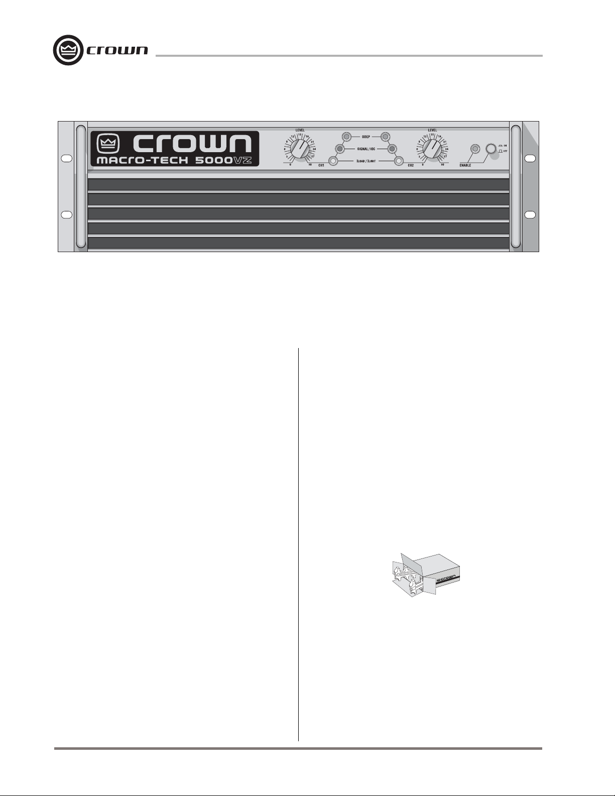
Fig. 1.1 Macro-Tech 5000VZ Amplifier
1 Welcome
Congratulations on your purchase of a
5000VZ
powerful and cost-effective professional amplifiers ever
made. From now on, you can enjoy the advantages of
having the highest level of innovation available in any
amplifier at any price.
The
fier to offer Crown’s patented Variable Impedance (VZ)
power supply technology. New semiconductor technology is combined with superior VZ power supplies to
enable the
edented power levels into 5¼ inches (13.3 cm) of vertical rack space. And because it is a
have the benefit of
going long after other amplifiers have failed—even under the most severe conditions. In addition, your amplifier provides enhanced
makes it easy to customize with a variety of popular
input modules (see Section 8.1 for a list of available
PIPTM
This manual will help you successfully install and use
your new amplifier. Please read all instructions, warnings and cautions. Be sure to read Sections 3.3.2 and
3.3.3 if you plan to use one of the amplifier’s two mono
modes. Also for your protection, please send in your
warranty registration card today and save your bill of
sale because it is your official proof of purchase.
.® You have selected one of the most reliable,
Macro-Tech 5000VZ
is the most advanced ampli-
Macro-Tech 5000VZ
®
and
PIP2
ODEP
modules).
protection to keep the show
PIP2
compatibility, which
Macro-Tech
to pack unprec-
Macro-Tech
, you
Macro-Tech 5000VZ Power Amplifier
®
bridged into a single 4-ohm load.* That’s a lot of power
for a unit that is only 5¼ inches (13.3 cm) tall and
weighs less than 80 pounds (36.3 kg).
There are many reasons to use amplifiers with an extremely high power density. As more loudspeakers are
driven with fewer amplifiers, audio systems become
more compact and efficient. If the system is used for
touring, this can reduce shipping costs and setup time.
But concentrating so much power in one amplifier creates potential hazards that can permanently ruin your
day. Your amplifier is capable of delivering enough
electrical power at the output terminals to produce a
lethal shock. If used improperly, it can also drive loudspeakers to levels that will cause permanent hearing
damage. For these reasons, we have included appropriate warnings and cautions in this manual.
1.2 Unpacking
Please unpack and inspect your new amplifier for any
damage that may have occurred during transit. If damage is found, notify the transportation company immediately. Only you, the consignee, may initiate a claim
for shipping damage. Crown will be happy to cooperate fully as needed. Save the shipping carton as evidence of damage for the shipper’s inspection.
Even if the unit arrived in perfect condition, as most
1.1 Why So Much Power?
The
Macro-Tech 5000VZ
per channel into 2-ohm stereo loads or 5,000 watts
Page 8
*Minimum guaranteed standard 1 kHz power with 120 volt, 60 Hz AC mains. See Section 6 for other AC mains voltages and frequencies.
can deliver up to 2,500 watts
do, save all packing materials so you will have them
if you ever need to transport the unit. NEVER SHIP
THE UNIT WITHOUT THE FACTORY PACK.
Reference Manual

Macro-Tech 5000VZ Power Amplifier
1.3 Features
The
Macro-Tech 5000VZ
and miniaturized design to provide the highest power and
value for its size, weight and price. Its patented
™
Bridge
circuitry offers many advantages over conventional designs. In Stereo mode, the amplifier’s separate
high-voltage supplies and ultra-low crosstalk make it possible to treat each channel as an independent amplifier.
Here are some more of its impressive features:
Patented Variable Impedance (VZ) power supplies for
each channel provide the best power matching to your
load. Three special modes are provided to control how
and when the supplies shift impedance modes.
Crown’s
age swings without using easily stressed output transistor
configurations like conventional amplifiers. The results
are lower distortion and superior reliability.
Patented
circuitry detects and compensates for overheating and
overload to keep the amplifier working when others
would fail. In addition,
VZ power supplies by shifting them into high-current
mode based on the requirements of the immediate conditions.
IOC
alerts you of any distortion that exceeds 0.05%, providing
dynamic
Enhanced
accepts accessory modules that tailor the amplifier to suit
individual applications, including wide-band load current
monitoring.
Convenient front panel indicators include an Enable indi-
cator for the low-voltage power supply, and an
Signal Presence/
channel.
Full protection against overvoltage, shorted outputs, mis-
matched loads, general overheating, DC and
high-frequency/RF overloads. Full internal fault protection.
“Standby” mode protects loudspeakers from low-
frequency/DC output, turn-on/turn-off transients and other
transients that can occur during an AC brownout.
Standby mode also provides overvoltage protection from
AC mains of more than 11% over the rated voltage.
Innovative Loudspeaker Offset Integration (LOI) circuitry
prevents asymmetrical audio waveforms from causing
off-center woofer cone movement.
Grounded Bridge
ODEP
®
(Input/Output Comparator) circuitry immediately
proof of distortion-free performance
PIP2
uses the very latest technology
Grounded
design delivers extreme volt-
(Output Device Emulation Protection)
ODEP
can be used to control the
.
(Programmable Input Processor) design
ODEP
IOC
and I
Load/ILimit
indicator for each
Each channel has an independent, error-driven com-
pressor that can be set for fast or slow attack and release
times.
Two custom toroidal power transformers (one per chan-
nel) provide maximum power transfer with minimum
electromagnetic fields.
The soft-start feature slowly brings the power supplies up
to full voltage to avoid tripping the breaker that protects
your AC wiring.
Universal power supplies can be easily reconfigured for
different AC mains voltages, making the amplifier convenient for use around the world.
Low harmonic and intermodulation distortion give the
best
dynamic transfer function
Superior damping factor delivers maximum loudspeaker
motion control.
Balanced inputs for each channel have independent
three-way input sensitivity switches.
The factory-installed PIP2-FXQ includes a ground lift
switch that can be used to isolate the AC (chassis)
ground from the XLR and phone jack input grounds.
Internal test ports provide rapid manufacturing and ser-
vice diagnostics.
Internal diagnostics LEDs make it easy to identify internal
operating conditions in the field.
Modular design makes service and maintenance much
more convenient.
The super-efficient cooling system features front-to-back
air flow with cutting edge heat sinks and proportional on-
,
demand forced-air cooling to prevent overheating and
prolong component life.
New touring chassis is extremely rugged and has been
torture-tested with over 100,000 miles of simulated road
abuse—even passing mil. spec. shock and vibration
testing.
Extruded aluminum front panel provides extra strength to
resist physical damage.
Rack mountable in a standard 19-inch (48.3-cm) equip-
ment rack (the back of the amplifier should be supported)
or units can be stacked directly on top of each other.
Three year “No-Fault” full warranty completely protects your
investment and guarantees its specifications.
in the industry.
Reference Manual
Page 9
2 Facilities
Macro-Tech 5000VZ Power Amplifier
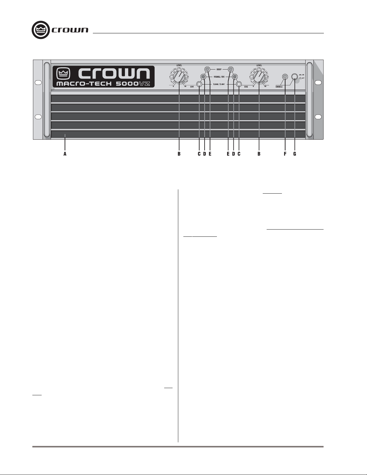
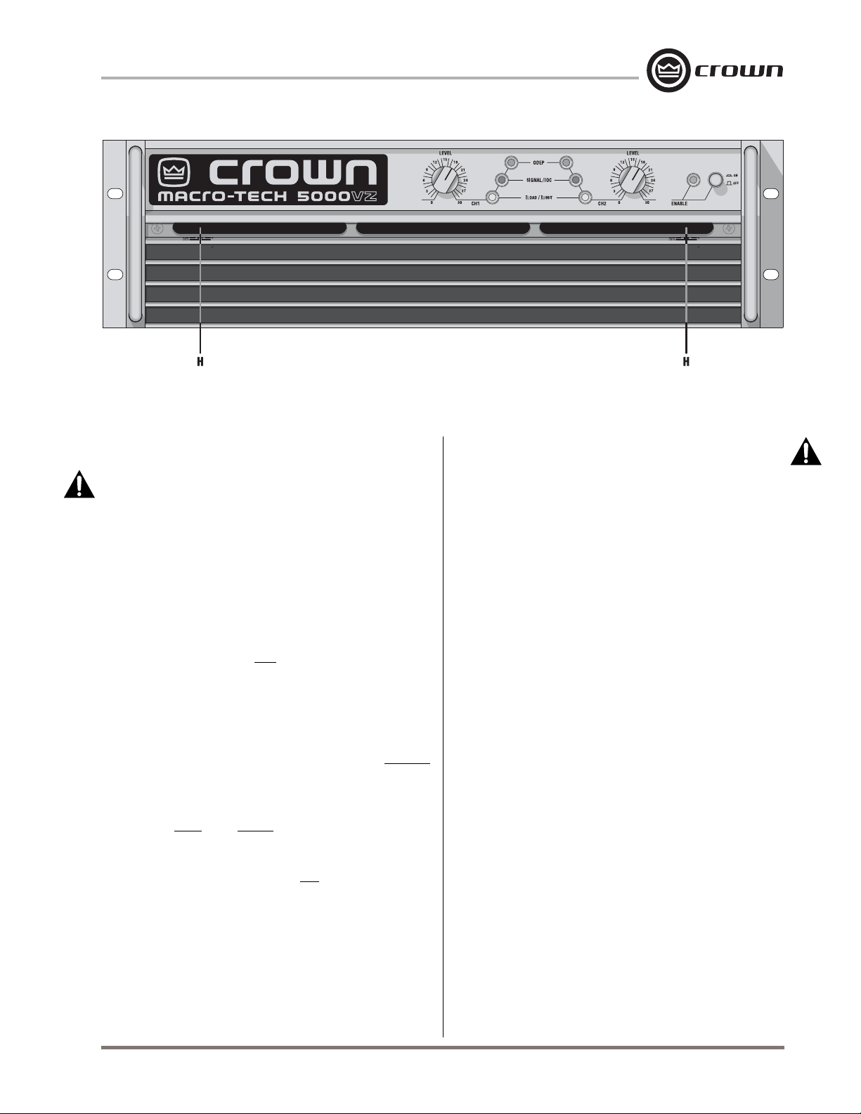
Fig. 2.1 Front Facilities
A. Dust Filters
The dust filters remove large particles from air drawn in
by the cooling fans. Check the filters regularly to prevent clogging (see Sections 3.2 and 4.5).
B. Level Controls
The output level for each channel is set with these convenient front panel level controls. Each control has
31 detents for precise adjustment (see Section 4.4). A
security option is also available to prevent tampering
(see Section 8.2).
C. I
Load/ILimit
The flow of current to the loudspeakers (“load current”)
and the maximum current limit of the amplifier (“limit
current”) are monitored by these two-color front panel
indicators. Normally, the I
green to show that load current is flowing. They turn off
when there is no significant load current. This happens
when there is no input signal, the input signal is at an
extremely low level, or there are no loads connected to
the amplifier’s outputs. They turn red if the amplifier has
reached its maximum output current capacity.
The I
Load/ILimit
the amplifier for maximum output. Just continue to connect additional loudspeakers in parallel with each output
until the I
erating conditions. The optimum load is achieved just before the indicator turns red (see Section 4.2).
Load/ILimit
D. Signal/
These green multifunction indicators show both signal
presence and distortion for each channel. As signal
presence indicators, they flash synchronously with the
amplifier’s audio output. As
Indicators
Load/ILimit
indicators are very useful when loading
indicator turns red under normal op-
IOC
Indicators
IOC
indicators glow
(Input/Output Com-
parator) indicators, they flash brightly with a 0.1 second hold delay if there is a difference of 0.05% or more
between the input and output audio waveforms.
“errors” occur most commonly when a large input signal causes an input overload or output clipping. The
IOC
function is also provided as
performance
E.
ODEP
During normal operation of the
Emulation Protection) circuitry, these amber indicators
glow brightly to show the presence of reserve thermaldynamic energy. They dim proportionally as energy
reserves decrease. In the rare event that energy reserves are depleted, the indicators turn off and
proportionally limits output drive so the amplifier can
safely continue operating even under severe conditions. These indicators also help to identify more unusual operating conditions (see Section 4.2).
(see Section 4.2).
Indicators
proof of distortion-free
ODEP
(Output Device
IOC
ODEP
F. Enable Indicator
This indicator lights when the amplifier has been turned
on (enabled) and has AC power (see Section 4.2).
G. Enable Switch
This push button is used to turn the amplifier on and
off. When turned on, the output is muted for about four
seconds to protect your system from start-up transients. This is why a power sequencer is rarely needed
for multiple units. (The length of the turn-on delay can
be changed. Contact Crown’s Technical Support
Group for details.)
H. VZ Mode Switches
A four-position switch is used to control the switching
Page 10
Reference Manual
Macro-Tech 5000VZ Power Amplifier
Fig. 2.2 Front Facilities behind the Filter Grille
mode for each power supply. The switches are located
behind the top dust filter about 1.75 inches (4.5 cm)
behind the front panel. Always turn off the power be-
fore changing either switch. To access the VZ mode
switches, remove the top dust filter and reach upward
through the grille opening with a long narrow nonconductive object like a plastic pen. The switches are easy
to locate with the aid of a flashlight. The switch for
Channel 1 is located to the left side of the amplifier,
while the switch for Channel 2 is located to the right.
From left to right, the four switch settings are VZ-ODEP,
Lock Low, VZ and VZ (the third and fourth switch positions are identical). The first switch position sets the
power supply to the VZ-ODEP switching mode, which
is the default setting from the factory. The VZ-ODEP
mode automatically shifts between high-current and
high-voltage modes as needed, except when
actively limits output drive, in which case the power
supply is locked in its high-current mode. The second
switch position is called “Lock Low.” It locks the power
supply in high-current mode so the amplifier will always
be ready to deliver maximum current to low-impedance
loads. The third and fourth switch positions set the
power supply to standard VZ mode. Standard VZ mode
automatically switches between high-current and highvoltage modes as needed, but is not affected by
(see Section 4.4).
ODEP
ODEP
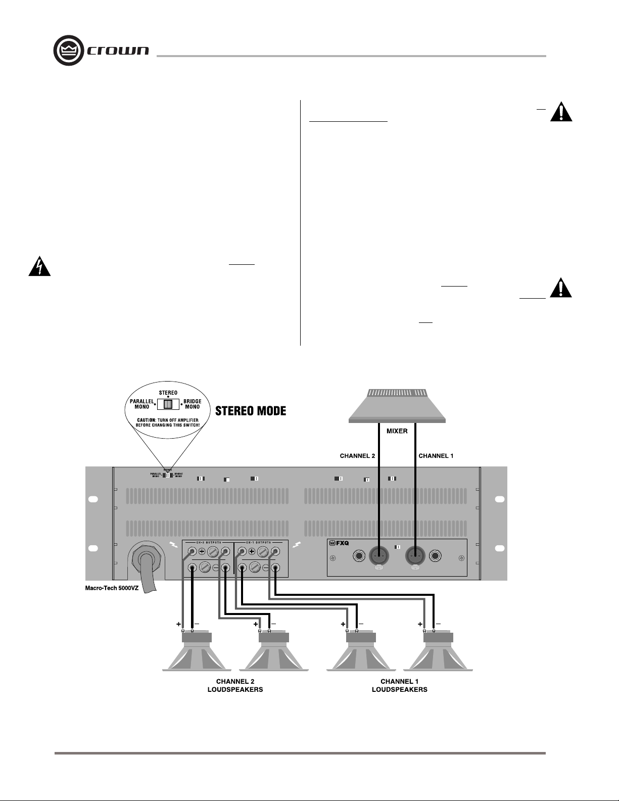
I. Stereo/Mono Switch
This switch is used to select one of three output modes.
Stereo mode is used for normal two-channel operation,
Bridge-Mono mode is used to drive a single channel
with a load impedance of at least 4 ohms, and ParallelMono mode is used to drive a single channel with a
load impedance less than 4 ohms. WARNING: The
amplifier should be off for at least 10 seconds before changing this switch (see Section 3.3).
J. Compressor Switches
A three-position back panel switch is provided to control each channel’s “error-driven” input compressor. Attack and release times can be set to either “fast” or
“slow,” or compression can be turned off for output clipping errors. The “fast” setting yields a 4-millisecond attack time and 300-millisecond release time. The “slow”
setting yields a 12-millisecond attack and 600-millisecond release (see Section 4.4).
K. Loudspeaker Offset Integration Switches
Each channel has a two-position back panel on/off
switch used to control the Loudspeaker Offset Integration (LOI) circuitry. LOI compensates for asymmetrical
audio waveforms that cause off-center woofer cone
movement (see Sections 3.3.4, 3.3.5 and 4.4).
L. Input Sensitivity Switches
These three-position back panel switches are used to
select the input sensitivity for each channel. Available
settings include 0.775 volts or 1.4 volts for standard
1 kHz output power, or a 26 dB voltage gain (see Section 4.4).
M. Power Cord
Units configured for 100 to 120 VAC have a 10-AWG,
30-amp line cord, while units set up for 200 to 240 VAC
have a 12-AWG, 20-amp line cord. North American
units configured for 120 VAC, 60 Hz power are shipped
with a grounded 125-volt, 30-amp NEMA TT30P plug;
units shipped outside North America are provided without a plug. See Sections 3.4 and 7 for AC requirements.
Reference Manual
Page 11
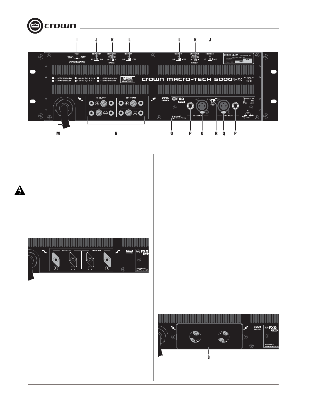
Fig. 2.3 Rear Facilities
Macro-Tech 5000VZ Power Amplifier
N. Output Connectors
This high-current output block is provided for output
connection. Its connectors accept banana plugs,
spade lugs or bare wire. The detachable output cover
(S) shown in Figure 2.5 is used to protect against accidental short circuits and dangerous electrical shock.
DANGER: The outputs can produce lethal energy
levels! Do not change the output wiring unless the
amplifier has been off for at least 10 seconds.
Some international models include high-current binding posts for output connection rather than the output
block shown in Figure 2.3. The international binding
posts are shown below in Figure 2.4:
Fig. 2.4 International Output Binding Posts
O.
PIP
Module
The standard PIP2-FXQ is included with your amplifier.
It provides female XLR and ¼-inch (6.35-mm) phone
jack input connectors. Each pair of XLR and phone jack
connectors is wired in parallel, so the unused connector can be used as a “daisy chain” output to connect a
source to multiple amplifiers. Other
ules can be used in place of the PIP2-FXQ to provide
additional features that customize the amplifier for different applications. Your amplifier is a
which means it can take advantage of the many advanced features found in
your amp can also use standard
the
PIP2
logo). See Section 8.1 for available
PIP2
modules.
PIP2
PIP
and
PIP2
mod-
PIP2
amplifier,
modules. In addition,
PIP
modules (without
PIP
and
P. Balanced Phone Jack Inputs
A balanced ¼-inch (6.35-mm) phone jack for each
channel is provided on the PIP2-FXQ. These phone
jacks can be used for signal input, or for “daisychained” output to other amplifiers. The phone jacks
may be used with either balanced (tip, ring and sleeve)
or unbalanced (tip and sleeve) wiring (see Section 3.3).
Note: The Channel 2 input is bypassed in either mono
mode.
Q. Balanced XLR Inputs
A balanced 3-pin female XLR connector is provided on
the PIP2-FXQ for input to each channel, or for “daisychained” output to other amplifiers.
Note: The Chan-
nel 2 input is bypassed in either mono mode.
R. Input Ground Lift Switch
This ground lift switch is located on the PIP2-FXQ. It is
used to isolate the input signal grounds from the AC
(chassis) ground to help prevent ground loops that can
result in unwanted hum and noise.
S. Output Cover
This protective cover is provided to prevent an electrical shock or short circuit at the output terminals.
Fig. 2.5 Output Cover
Page 12
Reference Manual
Macro-Tech 5000VZ Power Amplifier
3 Installation
3.1 Mounting
The
Macro-Tech 5000VZ
19 inch (48.3 cm) rack mounting and “stack” mounting
without a cabinet. For optimum cooling and rack support, multiple units should be stacked directly on top of
each other.
Important: Always support the back of the unit. Provide extra support if the unit will be transported.
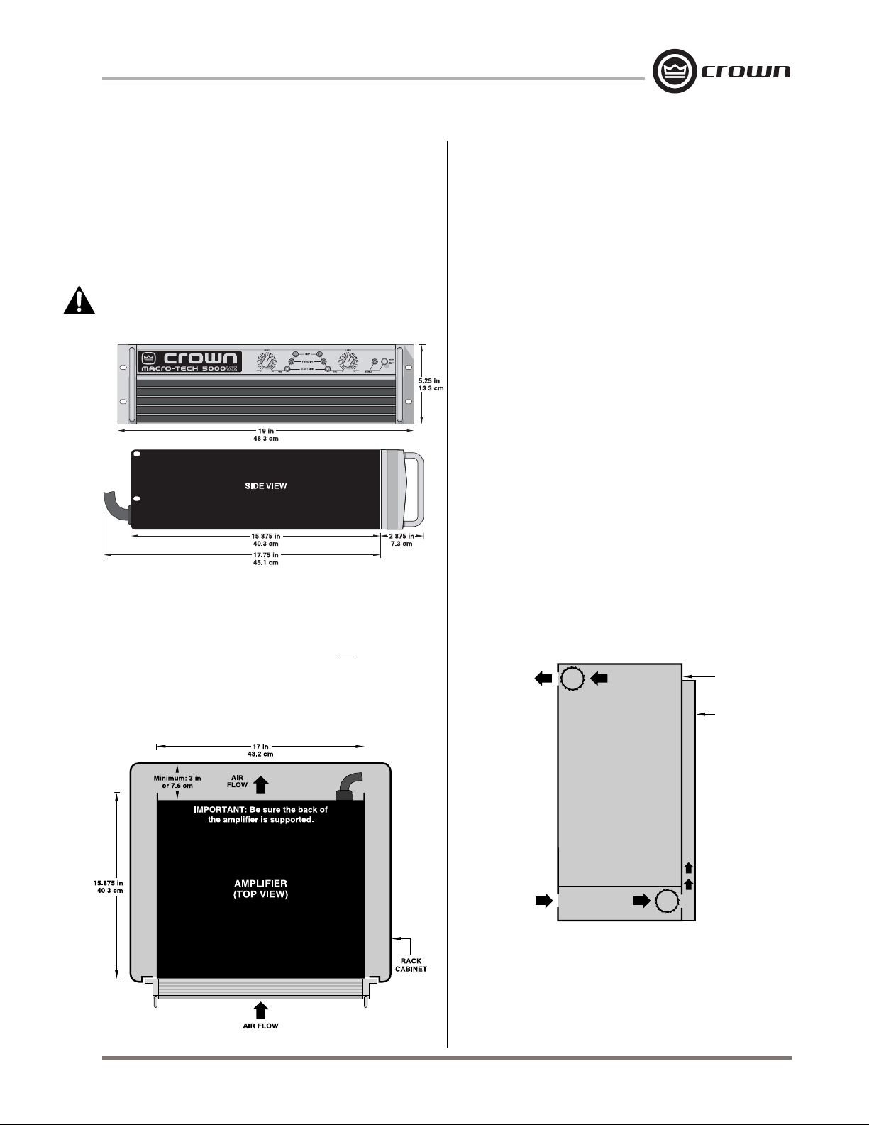
Fig. 3.1 Mounting Dimensions
3.2 Cooling
NEVER block the air vents in the front or back of the
amplifier.
mounted with space between them. If you must leave
open spaces in a rack for any reason, close them with
blank panels or recirculation will result. Allow for air flow
of at least 75 cubic feet (2.1 cubic meters) per minute
Macro-Tech
is designed for standard
amplifiers do not need to be
per unit. Additional air flow may be required when driving low-impedance loads at consistently high output
levels. Refer to Section 7 for detailed information on
thermal dissipation.
When mounting the amplifier in a rack cabinet, the back
wall of the rack should be at least 3 inches (7.6 cm)
away from the back of the amplifier chassis as shown
in Figure 3.2.
Tip:
An easy way to verify adequate cooling is to observe the ODEP indicators while the amplifier is operating under worst-case conditions. If the indicators dim,
additional cooling is recommended.
If your rack has a door that could block air flow to the
amplifier’s air intakes, you must provide adequate air
flow by installing a grille in the door or by pressurizing
the air behind the door. Wire grilles are recommended
over perforated panels because they tend to cause
less air restriction. A good choice for pressurizing the
air behind the rack cabinet door is to mount a “squirrel
cage” blower inside the rack (Option 1 below). At the
bottom of the rack, mount the blower so it blows outside air into the space between the door and front of
the amplifiers, pressurizing the “chimney” behind the
door. This blower should not blow air into or take air out
of the space behind the amplifiers. For racks without a
door, you can evacuate the rack by mounting the
blower at the top of the rack so that air inside the cabinet is drawn out the back (Option 2 below).
WARM
EXHAUST
BLOWER
(OPTION 2)
FRONT
OF
RACK
DOOR
Fig. 3.2 Top View of a Rack-Mounted Unit
Reference Manual
EQUIPMENT
RACK
(SIDE VIEW)
COOL AIR
INLET
BLOWER
(OPTION 1)
Fig. 3.3 Proper Air Flow in a Rack Cabinet
If the air supply is unusually dusty, you might want to
pre-filter it using commercial furnace filters to prevent
rapid loading of the unit’s own air filters. When needed,
the unit’s filters can be cleaned with mild dish detergent and water (see Section 4.5).
Page 13
Macro-Tech 5000VZ Power Amplifier
3.3 Wiring
The following instructions describe the most common
ways to install your amplifier in a sound system. The
input and output terminals are located on the back
panel. Please use care when making connections, selecting signal sources and controlling the output level.
The load you save may be your own! Crown assumes
no liability for personal injury or damaged loads from
careless amplifier use or deliberate overpowering. All
units include an output cover to prevent accidental
electrical shock and short circuits. We strongly recommend that you use this safety feature.
DANGER: The outputs can produce lethal energy
levels. Do not change the output wiring unless the
amplifier has been off for at least 10 seconds. Turn-
ing off the amplifier also reduces the chance of blasts
that can damage your hearing or loudspeakers.
Your amplifier can be operated in Stereo, Bridge-Mono,
or Parallel-Mono mode by switching the back panel ste-
reo/mono switch. Turn off the amplifier and wait at
least 10 seconds before changing this switch or internal damage to the circuitry may result. There are
VERY IMPORTANT wiring differences among the three
operating modes that will be discussed next.
3.3.1 Stereo (Two-Channel) Operation
In Stereo mode, installation is intuitive: input Channel 1
feeds output Channel 1, and input Channel 2 feeds output Channel 2. To activate Stereo mode, first turn off
the amplifier and wait 10 seconds for the power supply
to discharge. Then, slide the stereo/mono switch to the
center position, and connect the output wiring as
shown in Figure 3.4.
CAUTION: In Stereo mode, never parallel the two
outputs by directly tying them together, and never
parallel them with the output of another amplifier.
Such a connection does not result in increased power
output, but may result in overheating and premature
activation of the protection circuitry.
Page 14
Fig. 3.4 Stereo Wiring
Reference Manual
 Loading...