


Crown Com Tech 1610, Com Tech 210, Com Tech 410, Com Tech 810, CT-1610 Owners manual
...COM-TECH®
Models:
Com-Tech 210, 410, 810 & 1610
Some models may be exported under the name Amcron.®
© 2001 by Crown Audio, Inc., P.O. Box 1000, Elkhart, IN 46515-1000 U.S.A. Telephone: 219-294-8000. Fax: 219-294-8329. Trademark Notice: Amcron®, BCA® and Crown ® are registered trademarks of Crown International, Inc. Other trademarks are the property of their respective owners.
Obtaining Other Language Versions:
To obtain information in another language about the use of this product, please contact your local Crown Distributor. If you need assistance locating your local distributor, please contact Crown at 219-294-8200.
Note: The information provided in this manual was deemed accurate as of the publication date. However, updates to this information may have occurred. To obtain the latest version of this manual, please visit the Crown website at www.crownaudio.com.
Applies to
CT-410 and CT-810 Crown and Amcron models
101969-6 3/01

Com-Tech Power Amplifiers
This page intentionally left blank
Page 2 |
Reference Manual |

Com-Tech Power Amplifiers
Important Safety Instructions
1)Read these instructions.
2)Keep these instructions.
3)Heed all warnings.
4)Follow all instructions.
5)Do not use this apparatus near water.
6)Clean only with a dry cloth.
7)Do not block any ventilation openings. Install in accordance with the manufacturer’s instructions.
8)Do not install near any heat sources such as radiators, heat registers, stoves, or other apparatus that produce heat.
9)Do not defeat the safety purpose of the polarized or grounding-type plug. A polarized plug has two blades with one wider than the other. A groundingtype plug has two blades and a third grounding prong. The wide blade or the third prong is provided for your safety. If the provided plug does not fit into your outlet, consult an electrician for replacement of the obsolete outlet.
10)Protect the power cord from being walked on or pinched, particularly at plugs, convenience receptacles, and the point where they exit from the apparatus.
11)Only use attachments/accessories specified by the manufacturer.
12)Use only with a cart, stand, bracket, or table specified by the manufacturer, or sold with the apparatus. When a cart is used, use caution when moving the cart/apparatus combination to avoid injury from tipover.
13)Unplug this apparatus during lightning storms or when unused for long periods of time.
14)Refer all servicing to qualified service personnel. Servicing is required when the apparatus has been damaged in any way, such as power-supply cord or plug is damaged, liquid has been spilled or objects have fallen into the apparatus, the apparatus has been exposed to rain or moisture, does not operate normally, or has been dropped.
15)To reduce the risk of fire or electric shock, do not expose this apparatus to rain or moisture.
Reference Manual |
Page 3 |

 3
3 
 YEAR
YEAR 
THREE YEAR
FULL WARRANTY
 3
3 
 YEAR
YEAR 
WORLDWIDE |
NORTH AMERICA |
SUMMARY OF WARRANTY
The Crown Audio Division of Crown International, Inc., 1718 West Mishawaka Road, Elkhart, Indiana 46517-4095 U.S.A. warrants to you, the ORIGINAL PURCHASER and ANY SUBSEQUENT OWNER of each NEW Crown1 product, for a period of three (3) years from the date of purchase by the original purchaser (the “warranty period”) that the new Crown product is free of defects in materials and workmanship, and we further warrant the new Crown product regardless of the reason for failure, except as excluded in this Crown Warranty.
1 Note: If your unit bears the name “Amcron,” please substitute it for the name “Crown” in this warranty.
ITEMS EXCLUDED FROM THIS CROWN WARRANTY
This Crown Warranty is in effect only for failure of a new Crown product which occurred within the Warranty Period. It does not cover any product which has been damaged because of any intentional misuse, accident, negligence, or loss which is covered under any of your insurance contracts. This Crown Warranty also does not extend to the new Crown product if the serial number has been defaced, altered, or removed.
WHAT THE WARRANTOR WILL DO
We will remedy any defect, regardless of the reason for failure (except as excluded), by repair, replacement, or refund. We may not elect refund unless you agree, or unless we are unable to provide replacement, and repair is not practical or cannot be timely made. If a refund is elected, then you must make the defective or malfunctioning product available to us free and clear of all liens or other encumbrances. The refund will be equal to the actual purchase price, not including interest, insurance, closing costs, and other finance charges less a reasonable depreciation on the product from the date of original purchase. Warranty work can only be performed at our authorized service centers. We will remedy the defect and ship the product from the service center within a reasonable time after receipt of the defective product at our authorized service center.
HOW TO OBTAIN WARRANTY SERVICE
You must notify us of your need for warranty service not later than ninety (90) days after expiration of the warranty period. All components must be shipped in a factory pack. Corrective action will be taken within a reasonable time of the date of receipt of the defective product by our authorized service center. If the repairs made by our authorized service center are not satisfactory, notify our authorized service center immediately.
DISCLAIMER OF CONSEQUENTIAL AND INCIDENTAL DAMAGES
YOU ARE NOT ENTITLED TO RECOVER FROM US ANY INCIDENTAL DAMAGES RESULTING FROM ANY DEFECT IN THE NEW CROWN PRODUCT. THIS INCLUDES ANY DAMAGE TO ANOTHER PRODUCT OR PRODUCTS RESULTING FROM SUCH A DEFECT.
WARRANTY ALTERATIONS
No person has the authority to enlarge, amend, or modify this Crown Warranty. This Crown Warranty is not extended by the length of time which you are deprived of the use of the new Crown product. Repairs and replacement parts provided under the terms of this Crown Warranty shall carry only the unexpired portion of this Crown Warranty.
DESIGN CHANGES
We reserve the right to change the design of any product from time to time without notice and with no obligation to make corresponding changes in products previously manufactured.
LEGAL REMEDIES OF PURCHASER
No action to enforce this Crown Warranty shall be commenced later than ninety (90) days after expiration of the warranty period.
THIS STATEMENT OF WARRANTY SUPERSEDES ANY OTHERS CONTAINED IN THIS MANUAL FOR CROWN PRODUCTS.
9/90
Telephone: 219-294-8200. Facsimile: 219-294-8301
SUMMARY OF WARRANTY
The Crown Audio Division of Crown International, Inc., 1718 West Mishawaka Road, Elkhart, Indiana 46517-4095 U.S.A. warrants to you, the ORIGINAL PURCHASER and ANY SUBSEQUENT OWNER of each NEW Crown product, for a period of three (3) years from the date of purchase by the original purchaser (the “warranty period”) that the new Crown product is free of defects in materials and workmanship. We further warrant the new Crown product regardless of the reason for failure, except as excluded in this Warranty.
ITEMS EXCLUDED FROM THIS CROWN WARRANTY
This Crown Warranty is in effect only for failure of a new Crown product which occurred within the Warranty Period. It does not cover any product which has been damaged because of any intentional misuse, accident, negligence, or loss which is covered under any of your insurance contracts. This Crown Warranty also does not extend to the new Crown product if the serial number has been defaced, altered, or removed.
WHAT THE WARRANTOR WILL DO
We will remedy any defect, regardless of the reason for failure (except as excluded), by repair, replacement, or refund. We may not elect refund unless you agree, or unless we are unable to provide replacement, and repair is not practical or cannot be timely made. If a refund is elected, then you must make the defective or malfunctioning product available to us free and clear of all liens or other encumbrances. The refund will be equal to the actual purchase price, not including interest, insurance, closing costs, and other finance charges less a reasonable depreciation on the product from the date of original purchase. Warranty work can only be performed at our authorized service centers or at the factory. We will remedy the defect and ship the product from the service center or our factory within a reasonable time after receipt of the defective product at our authorized service center or our factory. All expenses in remedying the defect, including surface shipping costs in the United States, will be borne by us. (You must bear the expense of shipping the product between any foreign country and the port of entry in the United States and all taxes, duties, and other customs fees for such foreign shipments.)
HOW TO OBTAIN WARRANTY SERVICE
You must notify us of your need for warranty service not later than ninety (90) days after expiration of the warranty period. All components must be shipped in a factory pack, which, if needed, may be obtained from us free of charge. Corrective action will be taken within a reasonable time of the date of receipt of the defective product by us or our authorized service center. If the repairs made by us or our authorized service center are not satisfactory, notify us or our authorized service center immediately.
DISCLAIMER OF CONSEQUENTIAL AND INCIDENTAL DAMAGES
YOU ARE NOT ENTITLED TO RECOVER FROM US ANY INCIDENTAL DAMAGES RESULTING FROM ANY DEFECT IN THE NEW CROWN PRODUCT. THIS INCLUDES ANY DAMAGE TO ANOTHER PRODUCT OR PRODUCTS RESULTING FROM SUCH A DEFECT. SOME STATES DO
NOT ALLOW THE EXCLUSION OR LIMITATIONS OF INCIDENTAL OR CONSEQUENTIAL DAMAGES, SO THE ABOVE LIMITATION OR EXCLUSION MAY NOT APPLY TO YOU.
WARRANTY ALTERATIONS
No person has the authority to enlarge, amend, or modify this Crown Warranty. This Crown Warranty is not extended by the length of time which you are deprived of the use of the new Crown product. Repairs and replacement parts provided under the terms of this Crown Warranty shall carry only the unexpired portion of this Crown Warranty.
DESIGN CHANGES
We reserve the right to change the design of any product from time to time without notice and with no obligation to make corresponding changes in products previously manufactured.
LEGAL REMEDIES OF PURCHASER
THIS CROWN WARRANTY GIVES YOU SPECIFIC LEGAL RIGHTS, YOU MAY ALSO HAVE OTHER RIGHTS WHICH VARY FROM STATE TO STATE. No action to enforce this Crown Warranty shall be commenced later than ninety (90) days after expiration of the warranty period.
THIS STATEMENT OF WARRANTY SUPERSEDES ANY OTHERS CONTAINED IN THIS MANUAL FOR CROWN PRODUCTS.
Telephone: 219-294-8200. Facsimile: 219-294-8301 |
9/90 |
The information furnished in this manual does not include all of the details of design, production, or variations of the equipment. Nor does it cover every possible situation which may arise during installation, operation or maintenance. If your unit bears the name “Amcron,” please substitute it for the name “Crown” in this manual. If you need special assistance beyond the scope of this manual, please contact our Technical Support Group.
Crown Technical Support Group
Plant 2 SW, 1718 W. Mishawaka Rd., Elkhart, Indiana 46517 U.S.A.
Phone: 800-342-6939 (North America, Puerto Rico and Virgin Islands) or 219-294-8200 Fax: 219-294-8301 Internet: http://www.crownaudio.com
|
|
|
|
|
|
|
|
|
|
|
|
|
|
|
|
|
|
C A U T I O N |
|
|
A V I S |
|
|
|
|
|
|
|
|
|
|
|
|
RISK OF ELECTRIC SHOCK |
|
|
RISQUE DE CHOC ÉLECTRIQUE |
|
|
|
|
DO NOT OPEN |
|
|
N’OUVREZ PAS |
|
|
|
TO PREVENT ELECTRIC SHOCK DO |
À PRÉVENIR LE CHOC ÉLECTRIQUE |
|
||||
|
NOT REMOVE TOP OR BOTTOM |
N’ENLEVEZ PAS LES COUVERCLES. IL |
|
||||
|
COVERS. NO USER SERVICEABLE |
N’Y A PAS DES PARTIES |
|
||||
|
PARTS INSIDE. REFER SERVICING TO |
SERVICEABLE À L’INTÉRIEUR.TOUS |
|
||||
|
QUALIFIED SERVICE PERSONNEL. |
REPARATIONS DOIT ETRE FAIRE PAR |
|
||||
|
DISCONNECT POWER CORD BE- |
PERSONNEL QUALIFIÉ SEULMENT. |
|
||||
|
FORE REMOVING REAR INPUT |
DÉBRANCHER LA BORNE AVANT |
|
||||
|
MODULE TO ACCESS GAIN SWITCH. |
D’OUVRIR LA MODULE EN ARRIÈRE. |
|
||||
|
|
|
|
|
|
|
|
|
|
|
|
|
|
|
|
WARNING
TO REDUCE THE RISK OF ELECTRIC SHOCK, DO NOT EXPOSE THIS EQUIPMENT TO RAIN OR MOISTURE!
WATCH FOR THESE SYMBOLS:
The lightning bolt triangle is used to alert the user to the risk of electric shock.
Magnetic Field
CAUTION! Do not locate sensitive high-gain equipment such as preamplifiers or tape decks directly above or below the unit. Because this amplifier has a high power density, it has a strong magnetic field which can induce hum into unshielded devices that are located nearby. The field is strongest just above and below the unit.
If an equipment rack is used, we recommend locating the amplifier(s) in the bottom of the rack and the preamplifier or other sensitive equipment at the top.
The exclamation point |
|
triangle is used to alert the |
Printed on |
user to important operating |
|
or maintenance instructions. |
recycled paper. |

Com-Tech Power Amplifiers
|
|
|
|
CONTENTS |
|
1 |
Welcome ............................................................................ |
|
|
9 |
|
|
1.1 |
Unpacking ................................................................... |
|
9 |
|
|
1.2 |
Features....................................................................... |
|
9 |
|
2 |
Facilities .......................................................................... |
|
|
10 |
|
3 |
Installation ....................................................................... |
|
12 |
||
|
3.1 |
Mounting ................................................................... |
|
12 |
|
|
3.2 |
Cooling ...................................................................... |
|
12 |
|
|
|
3.2.1 Cooling for Units |
without Internal Fans ............. |
13 |
|
|
|
3.2.2 Additional Cooling for Units with Internal Fans . 13 |
|||
|
3.3 |
Wiring |
........................................................................ |
|
14 |
|
|
3.3.1 |
Mode of Operation .......................................... |
14 |
|
|
|
3.3.2 |
Audio Input Connection ................................... |
19 |
|
|
|
3.3.3 |
RSVP Input Connections .................................. |
21 |
|
|
|
3.3.4 |
Output Connection .......................................... |
21 |
|
|
|
3.3.5 |
Additional Load Protection ............................... |
23 |
|
|
3.4 |
AC Power Requirements ............................................ |
24 |
||
4 |
Operation ......................................................................... |
|
|
25 |
|
|
4.1 |
Precautions ................................................................ |
25 |
||
|
4.2 |
Indicators................................................................... |
25 |
||
|
4.3 |
Protection Systems .................................................... |
26 |
||
|
|
4.3.1 |
ODEP .............................................................. |
26 |
|
|
|
4.3.2 |
Standby Mode ................................................. |
27 |
|
|
|
4.3.3 |
Transformer Thermal Protection ....................... |
27 |
|
|
|
4.3.4 |
Circuit Breaker................................................. |
27 |
|
|
4.4 |
Controls ..................................................................... |
28 |
||
|
4.5 |
Energy Savings Circuit Application ............................ |
29 |
||
|
4.6 |
Filter Cleaning ............................................................ |
29 |
||
5 |
Technical Information ...................................................... |
29 |
|||
|
5.1 |
Overview ................................................................... |
29 |
||
|
5.2 |
Circuit Theory ............................................................ |
30 |
||
|
|
5.2.1 |
Dual Operation ................................................ |
30 |
|
|
|
5.2.2 |
Bridge-Mono Operation ................................... |
31 |
|
|
|
5.2.3 |
Parallel-Mono Operation .................................. |
31 |
|
6 |
Specifications .................................................................. |
32 |
|||
7 AC Power Draw and Thermal Dissipation ....................... |
45 |
||||
8 |
Accessories ..................................................................... |
47 |
|||
|
8.1 |
PIP and PIP2 Modules ................................................ |
47 |
||
|
8.2 |
RSVP Module ............................................................ |
49 |
||
|
8.3 |
Cooling Fan Option (120 VAC, 60 Hz only) ................. |
49 |
||
|
8.4 |
Constant Voltage Computer ....................................... |
49 |
||
9 |
Service ............................................................................. |
|
|
50 |
|
|
9.1 |
Worldwide Service ..................................................... |
50 |
||
|
9.2 |
North American Service ............................................. |
50 |
||
|
|
9.2.1 Service at a North American Service Center .... |
50 |
||
|
|
9.2.2 |
Factory Service ............................................... |
50 |
|
Page 6 |
Reference Manual |

Com-Tech Power Amplifiers
|
ILLUSTRATIONS |
|
1.1 |
Com-Tech Amplifiers (120 VAC, 60 Hz Units) ............................. |
8 |
2.1 |
Front Facilities ......................................................................... |
10 |
2.2 |
Rear Facilities ......................................................................... |
11 |
3.1 |
Mounting Dimensions .............................................................. |
12 |
3.2 |
Top View of a Rack-Mounted Unit ............................................ |
13 |
3.3 |
Extra Cooling with a Rack-Mounted Blower ............................. |
14 |
3.4 |
Wiring for Dual 8/4 Ohm Mode ................................................ |
15 |
3.5 |
Wiring for Dual 70 Volt Mode ................................................... |
16 |
3.6 |
Wiring for Bridge-Mono 70 Volt Mode (140 Volt Output) ........... |
17 |
3.7Wiring for Parallel-Mono 70 Volt, Bridge-Mono 8/4 Ohm
|
and Parallel-Mono 8/4 Ohm Modes ......................................... |
18 |
3.8 |
Balanced Input Wiring ............................................................. |
19 |
3.9 |
Unbalanced Input Wiring......................................................... |
19 |
3.10 Infrasonic Filter Capacitor Values ............................................ |
20 |
|
3.11 |
Unbalanced RFI Filters ............................................................ |
20 |
3.12 |
Balanced RFI Filters ................................................................ |
20 |
3.13 Connecting the RSVP Module ................................................. |
21 |
|
3.14 |
Wire Size Nomograph ............................................................. |
22 |
3.15 Inductive Load (Transformer) Network ..................................... |
23 |
|
3.16 |
Loudspeaker Fuse Nomograph ............................................... |
24 |
4.1 |
Indicators ................................................................................ |
25 |
4.2 |
ODEP, IOC and Signal Presence Indicator States .................... |
26 |
4.3 |
Input Sensitivity Switch ............................................................ |
28 |
5.1 |
Circuit Block Diagram ............................................................. |
30 |
6.1 |
Com-Tech 210 Minimum Power Matrix ..................................... |
35 |
6.2 |
Com-Tech 410 Minimum Power Matrix ..................................... |
36 |
6.3 |
Com-Tech 810 Minimum Power Matrix ..................................... |
37 |
6.4 |
Com-Tech 1610 Minimum Power Matrix ................................... |
38 |
6.5 |
Com-Tech 210 Maximum Power Matrix .................................... |
39 |
6.6 |
Com-Tech 410 Maximum Power Matrix .................................... |
40 |
6.7 |
Com-Tech 810 Maximum Power Matrix .................................... |
41 |
6.8 |
Com-Tech 1610 Maximum Power Matrix .................................. |
42 |
6.9 |
Typical Frequency Response .................................................. |
43 |
6.10 |
Typical Damping Factor .......................................................... |
43 |
6.11 |
Typical Output Impedance ...................................................... |
43 |
6.12 |
Typical Phase Response ......................................................... |
44 |
6.13 |
Typical Crosstalk ..................................................................... |
44 |
7.1Com-Tech 210 Power Draw, Current Draw and
Thermal Dissipation at Various Duty Cycles ............................. |
45 |
7.2Com-Tech 410 Power Draw, Current Draw and
Thermal Dissipation at Various Duty Cycles ............................. |
46 |
7.3Com-Tech 810 Power Draw, Current Draw and
Thermal Dissipation at Various Duty Cycles ............................. |
46 |
7.4Com-Tech 1610 Power Draw, Current Draw and
|
Thermal Dissipation at Various Duty Cycles ............................. |
46 |
8.1 |
PIP2 Adaptor Connection ........................................................ |
47 |
8.2 |
Installing a PIP Module ............................................................ |
47 |
Reference Manual |
Page 7 |

Com-Tech Power Amplifiers
Fig. 1.1 Com-Tech Amplifiers (120 VAC, 60 Hz Units)
Page 8 |
Reference Manual |
Com-Tech Power Amplifiers
1 Welcome
Congratulations on your purchase of a Com-Tech® commercial power amplifier. The Com-Tech series is a complete family of amplifiers with a wide range of power output capabilities. Com-Tech amplifiers can directly drive “constant voltage” lines, so you can avoid the expense, distortion and insertion loss associated with step-up transformers for distributed loudspeaker systems. Com-Tech amplifiers also utilize Crown’s patented ODEP® protection circuitry which keeps the amplifier working under severe conditions that would shut down a lesser amplifier. All Com-Tech amplifiers feature Crown’s exclusive PIP™ (Programmable Input Processor) expansion system. The PIP expansion system makes it easy to tailor your amplifier to a specific application or to add future technology as it develops (see Section 8 for a list of available PIPs).
This manual will help you successfully install and use your new Com-Tech amplifier. Please read all instructions, warnings and cautions. Be sure to read Section 3.3.1 if you plan to use the amplifier in one of its two mono modes, or if you plan to drive “constant voltage” lines. Also, for your protection, please send in your warranty registration card today, and save your bill of sale as it is your official proof of purchase.
1.1 Unpacking
Please unpack and inspect your new amplifier for any damage that may have occurred during transit. If damage is found, notify the transportation company immediately. Only you, the consignee, may initiate a claim for shipping damage. Crown will be happy to cooperate fully, as needed. Save the shipping carton as evidence of damage for the shipper’s inspection.
Even if the unit arrived in perfect condition, (as most do), save all packing materials, so you will have them if you ever need to transport the unit. NEVER SHIP THE
UNIT WITHOUT THE FACTORY PACK.
1.2 Features
Com-Tech amplifiers use cutting-edge technology and miniaturized design to provide the highest power and value for its size, weight and price. They offer numerous advantages over conventional designs and provide benefits you can’t get in amplifiers from any other manufacturer. For example, Crown’s patented ODEP protection circuitry and grounded bridge™ output stages combine to provide performance and reliability that surpass the other, more traditional, designs. Here are some more of your amplifier’s impressive features:
“Soft-Start” inrush current limiting protects the house circuit breaker when several amps are turned on simultaneously.
Remote feature allows CT-10 Series amplifiers to be turned on and off from a remote location. Placing the Enable switch on the amplifier’s front panel to the Remote position allows the optional R.S.V.P. (Remote Switching Voltage Provider) module to control the amplifier.
Energy Saving circuit allows a CT-10 Series amplifier to cut back its energy consumption based on the signal level offered to the inputs.
Crown’s patented ODEP (Output Device Emulation Protection) circuitry detects and compensates for overheating and overload to keep the amplifier working when others would fail.
Crown’s grounded bridge design delivers incredible voltage swings without using stressful output transistor configurations like conventional amplifiers. The results are lower distortion and superior reliability.
IOC ® (Input/Output Comparator) circuitry immediately alerts you if distortion is present. You have real-time proof of distortion-free performance.
Enhanced PIP2 (Programmable Input Processor) connector accepts new accessory modules that further tailor the amplifier to suit specific applications, including wideband load current monitoring.
Drives constant voltage lines without “lossy,” distortionproducing step-up transformers.
Two mono modes (Bridge-Mono and Parallel-Mono) for driving a wide range of load impedances.
Very low harmonic and intermodulation distortion give the best dynamic transfer function in the industry.
Superior damping factor delivers maximum loudspeaker motion control for a clean, accurate low end.
Superb crosstalk characteristics and a separate voltage supply for each channel make it possible to treat each channel like a separate amplifier.
Full protection from shorted, open and mismatched loads, general overheating. DC, high-frequency overloads, and full internal fault protection are provided by our latest protection scheme: “Quad-Mute.”
Efficient heat sinks and a fully proportial speed fan dissipate heat quickly and evenly for extra amplifier protection and extended component life. (The fan is an option for 120 VAC, 60 Hz Com-Tech 210s.)
Barrier blocks are provided for both input and output connections. New input barrier blocks incorporate a test point for a DVM.
Internal three-position input sensitivity switch provides settings of 0.775 volts for full standard 1-kHz 8/4-ohm power, 0.775 volts for full standard 1-kHz 70-volt power, and 26-dB voltage gain.
Mounts in a standard 19-inch (48.3-cm) equipment rack.
Three year “No-Fault” full warranty completely protects your investment and guarantees its specifications.
Reference Manual |
Page 9 |
Com-Tech Power Amplifiers
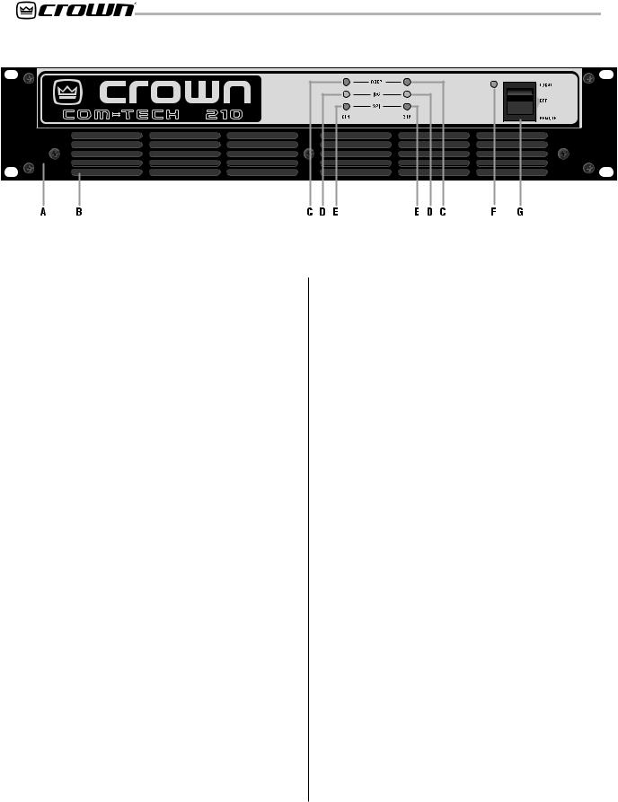
Fig. 2.1 Front Facilities
2 Facilities
A. Filter Grille
A metal grille supports and protects the dust filter (B). To clean the dust filter, detach the grille by removing the screws that fasten it in place.
B. Dust Filter
The dust filter removes large particles from air drawn by the cooling fan. (The fan is an option for 120 VAC, 60 Hz Com-Tech 210s.) Clean the filter regularly to prevent clogging (see Section 4.5).
C. ODEP Indicators
Each channel has an amber front panel indicator that shows thermal-dynamic energy reserve. Normally, each ODEP indicator is lit to show available reserve energy. The indicator will dim proportionally as the energy reserve for its channel decreases. In the rare event that a channel has no reserve, its indicator will turn off and the ODEP circuitry will limit the channel’s output drive (see Section 4.2).
D. IOC Indicators
The yellow IOC (Input/Output Comparator) indicators serve as sensitive distortion indicators to provide proof of distortion-free performance. Under normal conditions, the indicators remain off. They light up if the output waveform differs from the input by 0.05% or more. In addition, when the amplifier is running in parallel/ mono mode, CH2 IOC stays on under normal conditions (see Section 4.2).
E. Signal Presence Indicators (SPI)
The signal presence indicators flash synchronously with the amplifier’s audio output, when the output voltage is greater than 34 mV. (see Section 4.2).
F. Enable Indicator
This indicator lights when the amplifier has been enabled, or turned on, and AC power is available. The enable indicator will dim when the energy saving circuit is activated (see Section 4.2).
G. Enable Switch
This rocker switch is used to turn the amplifier on, off, and enable the remote feature. When turned on by either the rocker switch or the remote R.S.V.P. module, the output is muted for about four seconds to protect your system from any turn-on transients. Delay times vary slightly from one unit to the next, so there is always a certain amount of “randomness”. Turn-on inrush is limited by Soft-Start circuitry, so Com-Tech amplifiers never need a power sequencer. (To change the turn-on delay time, contact Crown’s Technical Support Group.)
H. Power Cord
All 120 VAC, 60 Hz North American units have a NEMA 5-15P plug with an integral voltage presence lamp. These units include a 16-gauge power cord with each Com-Tech 210 and 410, and a 14-gauge cord with each Com-Tech 810 and 1610. Other units have an appropriate power cord and plug. All Com-Tech “10” Series amps utilize a convenient 3-foot-long power cord.
To meet full regulatory compliance, these cords must be plugged into a local, cabinet mounted, commercial grade electrical outlet box. “Extension” cords are not recommended or adequate. Refer to Section 7 for more information on power usage.
I. Reset Switch
This reset switch is used to reset the circuit breaker that protects the power supplies from overload (see Sections 4.3.4 and 4.4).
|
|
|
|
|
|
Page 10 |
|
Reference Manual |
Com-Tech Power Amplifiers
Fig. 2.2 Rear Facilities
(Domestic Model Shown)
J. Dual/Mono Switch
For 8- and 4-ohm operation, remove the cover plate, if so equipped, then slide this switch to the center for Dual (two-channel) mode, to the left for Parallel-Mono mode or to the right for Bridge-Mono mode.
WARNING: Do not change this switch unless the amplifier is turned off. Do NOT use the Bridge-Mono or Parallel-Mono modes unless both output mode switches (O) are set the same. Also, be sure to follow the installation requirements for each mode (see Section 3.3.1).
K. Remote Input
For remote operation, an RJ11 jack is used to connect the amplifier to the optional R.S.V.P. (Remote Switching Voltage Provider) module. Do not connect to phone line.
L. PIP Module
The standard PIP2-BB is included with your amplifier. It provides barrier block input connectors equipped with test points for your DVM. Other PIP modules can be used in place of the PIP2-BB to provide additional features that customize the amplifier for different applications. First generation PIPs require the “PIP2 Adapter” for accessory connectivity (see Section 8 for available PIP modules).
M. Input Sensitivity Switch (not shown)
The three-position Input Sensitivity Switch located inside the amplifier is accessed by removing the PIP module. It is set at the factory to 0.775 volts for maximum average power (1 kHz power into 8 ohms). It can
also be set to 0.775 volts for 1 kHz output in 70-volt mode, or an overall voltage gain of 26 dB (see Section 4.4).
N. Input Attenuation Controls
Each channel’s output level can be adjusted accurately using these 21-position detented controls on the back panel. A Lexan cover is also included that can be used to discourage tampering (see Section 4.4).
O. Balanced Barrier Block Inputs
The PIP2-BB is included in the standard configuration. It provides a balanced barrier block with three terminals for each input channel, as well as test points for a DVM. (XLR connectors are also available—see Section 8.1.)
P. Output Mode Switches
The output mode switches are used to configure each channel independently for either 8/4-ohm loads or 70volt (“constant voltage”) lines.
WARNING: Do not change these switches unless the amplifier is off. Do NOT use the Bridge-Mono or Par- allel-Mono modes unless these switches are set the same. Also, be sure to follow the special installation requirements for each mode (see Section 3.3.1).
Q. Output Barrier Block
A barrier block with four terminals is provided for output connection. Output wiring will vary depending on the selected dual/mono mode and whether 70-volt output will be used (see Section 3.3.1).
|
|
|
|
|
|
Reference Manual |
|
Page 11 |
Com-Tech Power Amplifiers
3 Installation
This section covers basic Com-Tech installation procedures. All Com-Tech amplifiers are intended for rack mount installations using a commercial 19-inch (48.3-cm) EIA rack standard metal cabinet wired with a commercial grade electrical outlet box and receptacles. All Com-Tech Amplifiers utilize a convenient 3-foot long (0.9-m) power cord for such installations.
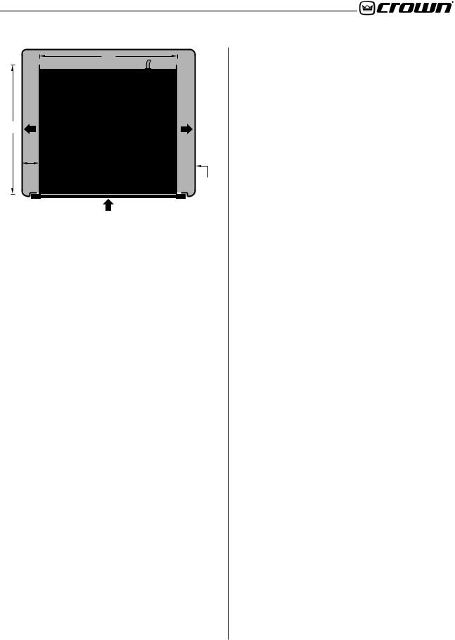
3.1 Mounting
Com-Tech amplifiers are designed for standard 19-inch (48.3-cm) rack mounting or stacking without a cabinet. In a rack, it is best to mount units directly on top of each other. This provides the most efficient air flow and support. If the rack will be transported, we recommend that you fasten the amplifier’s back panel securely to the rack to help support the unit’s weight.
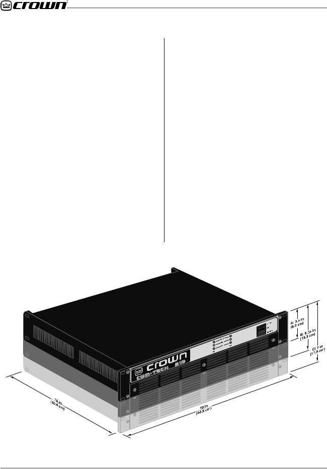
All Com-Tech amplifiers are 19 inches (48.3 cm) wide, 16 inches (40.6 cm) deep, and 0.25 inches (0.6 cm) in front of the mounting surface. As you can see in Figure 3.1, Com-Tech amplifiers vary in their vertical dimensions. Figure 3.1 labels the different heights as A, B and C. These letters correspond to the list that follows showing Com-Tech models and their vertical dimen-
|
sions. |
|
|
|
|
|
Height A: |
3.5 inches (8.9 cm) |
|
Models: |
Com-Tech 210 (All) |
|
|
Com-Tech 410 (North American) |
|
Height B: |
5.25 inches (13.3 cm) |
|
Models: |
Com-Tech 410 (100/120 VAC, 50/60 Hz) |
|
|
Com-Tech 410 (220/240 VAC, 50/60 Hz) |
|
|
Com-Tech 810 (All) |
|
Height C: |
7 inches (17.8 cm) |
|
Model: |
Com-Tech 1610 (All) |
3.2 Cooling
It is important to understand cooling considerations when installing a Com-Tech amplifier. First, never block the amplifier’s front or side air vents. This can cause poor air flow and may result in overheating. If the amplifier is rack-mounted, its sides should be at least 2 inches (5 cm) away from the cabinet (see Figure 3.2). Also, open spaces in the front of the rack should be covered with blank panels to prevent improper air flow. Otherwise, heated air from the side exhaust vents can be drawn into the front air intake which may greatly reduce the cooling system’s effectiveness.
Fig. 3.1 Mounting Dimensions
Page 12 |
Reference Manual |
Com-Tech Power Amplifiers
AIR
FLOW
16 in
40.6 cm
2 in (5 cm) MIN.
17 in
43.2 cm
IMPORTANT: Be sure the back of the amplifier is supported.
AIR
FLOW
AMPLIFIER (TOP VIEW)
RACK
CABINET
AIR FLOW
Fig. 3.2 Top View of a Rack-Mounted Unit
The air flow requirement for a Com-Tech amplifier depends on many things, but the most important factor is average output power. Air flow requirements increase as output power increases, so anything that affects output power also affects the required air flow.
Average output power is mainly affected by three things: (1) duty cycle of the input signal, (2) load impedance, and (3) rated output power. First, as the duty cycle of the input signal increases, the average output power level increases. For example, the amplifier will need more air flow with a rock ‘n’ roll input signal than with infrequent paging. Second, as the load impedance of a connected loudspeaker gets smaller, more current will flow through the load which effectively increases output power. This means you can expect the amplifier to require more air flow with a 4-ohm load than with an 8-ohm load. Finally, an amplifier that is rated for higher power output is usually used at higher average output levels. So a Com-Tech 1610 delivering full output will require more air flow than a Com-Tech 210. These relationships and the resulting thermal dissipation levels are defined mathematically in Section 7.
3.2.1 Cooling for Units without Internal Fans
All units have a continuously variable on-demand cooling fan except for the North American Com-Tech 210. Forced-air cooling may not be needed for applications with a low duty cycle such as paging or background music. This is why the North American Com-Tech 210 is usually provided without a fan.
If you will be using a North American Com-Tech 210 in a high-temperature environment, or at full power for sustained periods, you can anticipate that additional cooling will be needed. It may also be helpful to use the
information in Section 7 to estimate the amplifier’s thermal dissipation for your application. In general, a North American Com-Tech 210 that dissipates more than 410 btu (110 kcal) per hour per unit will need additional cooling. If you are not sure, observe the ODEP indicators while the amplifier is operating under worst-case conditions. If the indicators dim, additional cooling is recommended.
There are at least three ways to provide extra cooling for an amplifier that does not have an internal fan. The most effective method is to install an internal fan which is available from Crown as an accessory (refer to subsection 8.3). A cooling fan (part GCT200FAN) kit is available for North American Com-Tech 210s (all other units include a fan). Crown recommends the kit if you will be operating the amplifier at high levels or in high temperatures for long periods. Refer to paragraph 8.3 for more information on the cooling fan kit
A rack-mounted blower or an air conditioner can also be used to provide extra cooling. In some situations, you may find it practical to use these methods without installing a fan in each amplifier. However, we generally recommend that you use the internal fans because they provide the most efficient cooling, and are active only when needed. Amplifiers that already have internal fans can also take advantage of a rack-mounted blower or air conditioner, so these approaches will be discussed in the section that follows.
3.2.2 Additional Cooling for Units with Internal Fans
If multiple amplifiers will be operated under demanding conditions (such as driving loads less than 4 ohms), or if air flow through the rack will be restricted, you should verify that the total air flow through the rack will be sufficient. As described in Section 3.2.1, sufficient air flow can be tested in the real world by observing the ODEP indicators while operating under worst-case conditions. If the indicators dim, cooling can be improved by reducing air restrictions, installing a rack-mounted blower, or using an air conditioner.
Many things can cause air flow restrictions, including improper mounting, bunched up power cords, closed rack doors, and clogged dust filters. A Com-Tech amplifier should be mounted in a way that allows sufficient air flow into the front intakes, out the side exhaust vents, and out the back of the rack. If your rack has a front door, it is usually best to leave it open and avoid blocking the air intakes. If this is impossible, supplement the air flow by mounting a grille in the door or with a rackmounted blower. If you install a grille in the door, we recommend wire grilles instead of perforated panels,
|
|
|
|
|
|
Reference Manual |
|
Page 13 |

Com-Tech Power Amplifiers
AIR |
BLOWER |
FRONT |
|
OF |
|||
FLOW |
(OPTION 2) |
||
RACK |
|||
|
|
DOOR |
EQUIPMENT
RACK
(SIDE VIEW)
AIR |
BLOWER |
FLOW |
(OPTION 1) |
Fig. 3.3 Extra Cooling with a Rack-Mounted Blower
because wire tends to cause less air restriction (perforated panels cause a minimum air restriction of 40%).
A better choice for increasing the air flow behind a rack cabinet door is to use a “squirrel cage” blower. Mount the blower at the bottom of the rack so it blows outside air into the space between the door and the front of the amplifiers, pressurizing the “chimney” behind the door (Figure 3.3, Option 1). The blower should not blow air into or take air out of the space behind the amplifiers. For racks without a front door, you can evacuate the rack by mounting the blower at the top of the rack so that air blows out the back (Figure 3.3, Option 2).
You can estimate the required air flow for a rack by adding together the maximum required air flow ratings of the individual units. The internal fan in a Com-Tech 210 (if installed), 410 and 810 can move up to 35 cubic feet (1 cubic meter) of air per minute, while the internal fan in a Com-Tech 1610 can move up to 65 cubic feet (1.8 cubic meters) per minute. If you mounted one of each Com-Tech model in a rack, worst-case conditions would require 170 cubic feet (4.7 cubic meters) of air flow through the rack every minute (3 x 35 cubic feet + 65 cubic feet = 170 cubic feet).
Air flow restrictions may also result if the air filter becomes clogged. If the air supply is unusually dusty, you can help prevent rapid loading of the unit’s air filter by pre-filtering the air using commercial furnace filters. And, when needed, the unit's filter can be cleaned with mild dish detergent and water (see Section 4.6).
The final method for increased cooling is to use air conditioning. Air conditioning is rarely a necessity because internal fans and rack-mounted blowers almost always
provide enough air flow for even the most extreme conditions. Still, air conditioning can help by reducing the temperature of the air circulated through the rack. If you intend to install air conditioning for your amplifiers, you may want to use Section 7 to determine the hourly thermal dissipation of your system.
3.3 Wiring
Figures 3.4 through 3.7 show common ways to install a Com-Tech amplifier in a sound system. Input and output terminals are located on the back panel. Please use care when making connections, selecting signal sources and controlling the output level. The load you save may be your own! Crown assumes no liability for damaged loads resulting from careless amplifier use or deliberate overpowering.
CAUTION: Always disconnect the AC power and turn the level controls off when making or breaking connections. This is very important when loudspeakers are connected because it reduces the chance of loud blasts that can cause loudspeaker damage.
3.3.1 Mode of Operation
Proper wiring depends on how you configure your amplifier. First, each output channel can be independently configured to drive step-down transformers in a distributed “constant voltage” loudspeaker system (70-volt mode) or loudspeakers that do not have step-down transformers (8/4-ohm mode). Second, the amplifier can be configured for Dual, Bridge-Mono or ParallelMono modes. Various combinations of these modes are possible, so be sure to note any special wiring requirements for the mode you will be using.
8/4 |
70 |
OHM |
VOLT |
7 0 V O L T
The 70-volt output mode is used to drive constant voltage lines without expensive step-up transformers. Avoiding the use of step-up transformers not only saves money, but it also eliminates the distortion and insertion loss caused by this type of transformer.
Setting up 70-volt mode is easy. Turn off the amplifier, then slide the recessed output mode switches to the 70 VOLT (right) position.
If required by your system design, Com-Tech amplifiers can be configured for either bridge-mono or parallelmono modes of operation. To switch your amplifier accordingly, start by removing power from the unit. Next,
|
|
|
|
|
|
Page 14 |
|
Reference Manual |
Com-Tech Power Amplifiers
remove the “Dual-Mono” mode switch cover and set the switch to the desired setting. Then replace the switch cover plate before restoring power.
WARNING: If you have configured the amplifier to produce 100 volts output or greater, your output wiring must conform to the National Electrical Code Class 1 wiring requirements.
If Bridge-Mono mode is used with 70-volt output, the amplifier will actually deliver 140 volts (more information on this is provided later in this section). To effectively use this mode, you may need to cross-reference power ratings for the step-down transformer taps using Crown’s constant voltage computer (see Section 8.3).
WARNING: The output mode switches must be set the same (8/4-ohm or 70-volt mode) when operating in Bridge-Mono or Parallel-Mono mode.
When connecting a 70-volt step-down transformer, do not exceed its power rating. Too much power can saturate a transformer and cause it to appear as a short circuit to the amplifier. If this happens, no damage should occur, but the amplifier may run less efficiently, and the sound quality may be affected.
8/4 |
70 |
OHM |
VOLT |
8 / 4 O H M
8/4-ohm mode is commonly used to drive loudspeakers with impedances from 2 to 16 ohms. When using this output mode, appropriate load impedances will depend on the dual/mono mode that you select. The available dual/mono modes (Dual, Bridge-Mono and Parallel-Mono) will be described in sections that follow.
Configuring your amplifier for 8/4-ohm mode is straightforward. Turn off the amplifier and slide the output mode switches to the 8/4 OHM (left) position.
When the amplifier is set up for two-channel (Dual mode) operation, it is possible to configure one output channel for 8/4-ohm operation and the other for 70-volt operation. If you plan to use different output modes like this, the input sensitivity should be set to 0.775-volts for 70-volt output. This will assure you of having enough amplifier gain to reach 70-volt output levels with a .775volt input signal. The 8/4-ohm channel will need to have it’s level control turned down so that a .775-volt input signal will not overdrive that channel (see Section 4.4). ALWAYS configure both channels the same when using Bridge-Mono or Parallel-Mono modes.
Because of the way Com-Tech amplifiers are designed, they can be used to directly drive constant voltage lines in 8/4-ohm mode. Being able to use lower constant voltage levels can be very convenient if building codes or other obstacles do not permit higher constant voltage levels. When 8/4-ohm mode is used to drive a distrib-
CHANNEL 1 |
8/4 |
70 |
8/4 |
70 |
TURN OFF THE AMPLIFIER |
|
|
|
BEFORE CHANGING THE |
||||
|
|
OHM |
VOLT |
OHM |
VOLT |
|
|
|
|
|
|
|
OUTPUT MODE SWITCHES. |
CHANNEL 2 |
|
CH2 |
|
CH1 |
|
|
MIXER |
|
|
|
|
|
|
REMOTE |
BB |
CH1 |
|
|
|
|
PUSH TO RESET |
CH2 |
|
|
|
|
|
|
|
|
|
|
|
|
E |
SS |
PR |
R E SET |
|
|
|
|
|
|
|
|
|
|
|
Programmable |
+ |
– |
+ |
– |
|
|
|
|
|||
Input Processor (P.I.P.) |
|
|
|
|
|
|
|
||||
13 11 10 |
9 |
8 |
7 |
|
|
|
13 11 10 |
9 |
8 |
7 |
|
15 |
|
|
6 |
|
|
|
15 |
|
|
6 |
|
17 |
|
|
|
5 |
|
|
17 |
|
|
5 |
|
19 |
|
|
|
4 |
|
|
19 |
|
|
4 |
|
21 |
|
|
|
3 |
|
|
21 |
|
|
3 |
|
25 |
|
|
|
2 |
|
|
25 |
|
|
2 |
|
32 |
|
|
|
1 |
|
|
32 |
|
|
1 |
|
dB |
|
0 .5 |
CH-2 |
|
|
CH-1 dB |
|
0 .5 |
|
||
Com-Tech Amplifier |
|
|
|
|
|
|
|
|
|
|
+ |
|
|
|
|
|
|
|
|
|
|
|
|
|
|
|
|
|
|
|
|
|
|
CHANNEL 1 |
– |
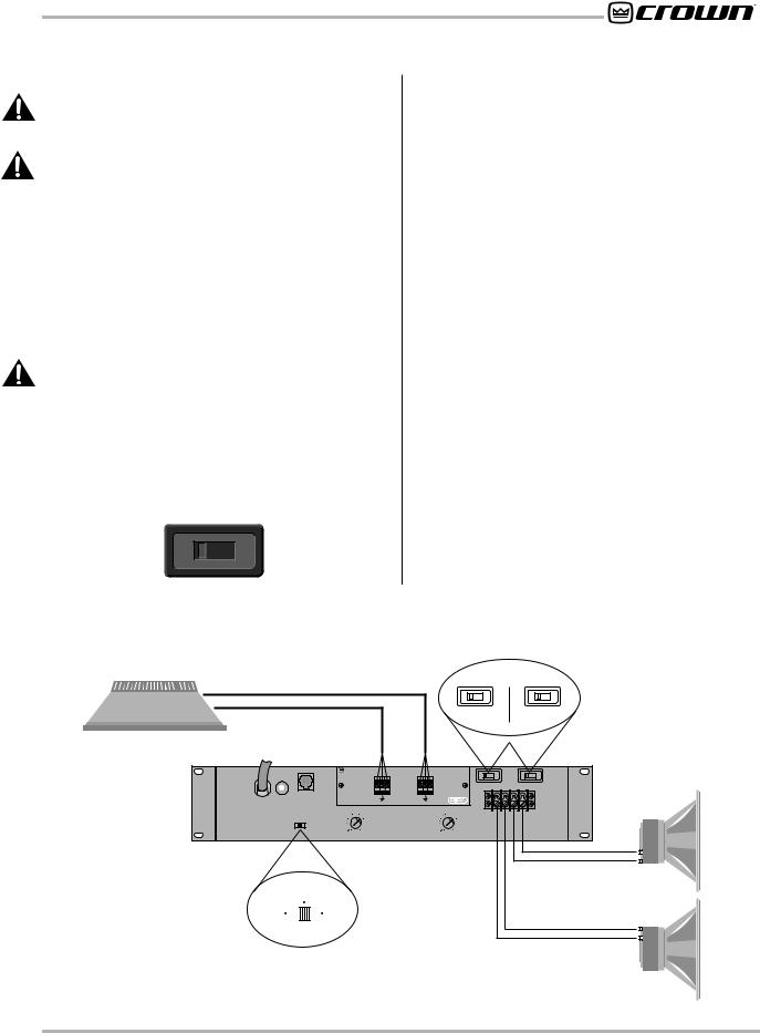
DUAL 8/4 OHM MODE |
|
DUAL |
TURN OFF THE AMPLIFIER |
|
LOUDSPEAKERS |
|
(BOTH CHANNELS) |
|
|
|
|||
PARALLEL |
|
BRIDGE |
|
|
||
|
BEFORE CHANGING |
|
|
|||
|
MONO |
|
MONO |
THE DUAL/MONO SWITCH. |
CHANNEL 2 |
– |
|
|
|
|
|||
|
|
|
|
|
||
+
Fig. 3.4 Wiring for Dual 8/4-Ohm Mode
Reference Manual |
Page 15 |
Com-Tech Power Amplifiers
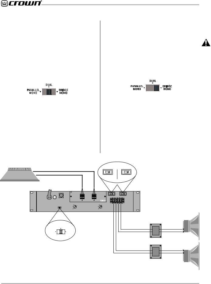
uted loudspeaker system, the constant voltage output varies with the output power rating of the amplifier. With 8/4-ohm output in Dual or Parallel-Mono mode, the Com-Tech 210 can drive a 25-volt line, the Com-Tech 410 can drive a 35-volt line, the Com-Tech 810 can drive a 50-volt line, and the Com-Tech 1610 can drive a 70volt line. Using Bridge-Mono mode, these voltage levels are doubled for a single channel. Again, to effectively use different constant voltage levels, you may need to cross reference the ratings for the step-down transformers’ taps using Crown’s constant voltage computer (see Section 8.3).
D U A L
Dual mode allows each amplifier channel to operate independently like a “dual mono” or stereo amplifier. And if you select both Dual mode and 70-volt output, each output channel can drive a 70-volt line. Installation is intuitive: Input Channel 1 feeds output channel 1, and input Channel 2 feeds output Channel 2.
To put the amplifier into Dual mode, turn it off, slide the dual/mono switch to the DUAL (center) position, and properly connect the output wiring. Be sure to observe
correct loudspeaker polarity (see Figure 3.4) and be careful not to short the two outputs.
CAUTION: Never tie an amplifier’s outputs together directly while in dual mode. Never parallel them with the output of another amplifier. Such connections do not result in increased output power, but may cause overheating and premature activation of the protection circuitry.
Note: To parallel multiple amplifiers for fail-safe redundancy, contact Crown’s Technical Support Group.
B R I D G E - M O N O
Bridge-Mono mode is used to drive loads with a total impedance of at least 8 ohms (see Parallel-Mono if the load is less than 4 ohms). If Bridge-Mono mode and 70volt output are used together, twice the normal output voltage is produced from a single channel to drive 140volt distributed loudspeaker systems. If you will be using 140-volt output, you may need to cross-reference the ratings of the step-down transformer taps with Crown’s constant voltage computer (see Section 8.3). If you need a single channel with higher power to drive a 70-volt line, use Parallel-Mono mode.
|
|
CHANNEL 1 |
|
|
|
|
|
|
|
8/4 |
|
70 |
8/4 |
70 |
|
TURN OFF THE AMPLIFIER |
|
|||
|
|
|
|
|
|
|
|
|
|
|
|
|
BEFORE CHANGING THE |
|
||||||
|
|
|
|
|
|
|
|
|
|
|
OHM |
VOLT |
OHM |
VOLT |
|
|
||||
|
|
|
|
|
|
|
|
|
|
|
|
|
|
|
|
|
|
OUTPUT MODE SWITCHES. |
|
|
|
|
CHANNEL 2 |
|
|
|
|
|
|
|
|
|
|
|
CH2 |
|
CH1 |
|
|
|
|
MIXER |
|
|
|
|
|
|
|
|
|
|
|
|
|
|
|
|
|
|
|
|
|
|
REMOTE |
BB |
|
|
|
|
CH2 |
|
CH1 |
|
|
|
|
|
|
|
|
|
|
|
PUSH TO RESET |
|
|
|
|
|
|
|
|
|
|
|
|
|
|
|
|
|||
|
|
|
|
|
|
|
|
|
|
|
|
|
|
|
|
|
|
|
||
|
E |
SS |
|
|
|
|
|
|
|
|
|
|
|
|
|
|
|
|
|
|
|
PR |
|
|
|
|
|
|
|
|
|
|
|
|
|
|
|
|
|
|
|
|
R E SET |
|
|
|
|
|
|
|
|
|
|
|
|
|
|
|
|
|
|
|
|
|
|
Programmable |
+ |
– |
+ |
– |
|
|
|
|
|
|
|
|
|
|
|||
|
|
|
Input Processor (P.I.P.) |
|
|
|
|
|
|
|
|
|
|
|
|
|
||||
|
|
|
13 11 10 |
9 |
8 |
7 |
|
|
|
15 |
13 11 10 |
9 |
8 |
7 |
|
|
|
|
|
|
|
|
|
15 |
|
|
6 |
|
|
|
|
|
|
6 |
|
|
|
|
|
|
|
|
|
|
17 |
|
|
|
5 |
|
|
17 |
|
|
|
5 |
|
|
|
|
|
|
|
|
|
19 |
|
|
|
4 |
|
|
19 |
|
|
|
4 |
|
|
|
|
|
|
|
|
|
21 |
|
|
|
3 |
|
|
21 |
|
|
|
3 |
|
|
|
|
|
|
|
|
|
25 |
|
|
|
2 |
|
|
25 |
|
|
|
2 |
|
|
|
|
|
|
|
|
|
32 |
|
|
|
1 |
|
|
32 |
|
|
|
1 |
|
|
|
|
|
|
|
|
|
dB |
|
0 .5 |
CH-2 |
|
|
CH-1 |
dB |
|
0 .5 |
|
|
|
|
|
|
||
Com-Tech Amplifier |
|
|
|
|
|
|
|
|
|
|
|
|
|
|
|
|
|
|
|
|
DUAL 70 VOLT MODE |
|
DUAL |
|
|
|
|
TURN OFF THE AMPLIFIER |
|
|
|
|
+ |
+ |
|||||||
(BOTH CHANNELS) |
PARALLEL |
BRIDGE |
|
|
|
|
BEFORE CHANGING |
|
|
|
|
|
|
|
16, 8, OR 4 OHM |
– |
||||
MONO |
|
MONO |
|
|
|
THE DUAL/MONO SWITCH. |
|
|
CHANNEL 1 |
|
COM |
|||||||||
|
|
|
|
|
|
|
|
|
|
|
|
|
|
|
|
|
|
|
|
|
|
|
|
|
|
|
|
|
|
|
|
|
|
|
|
|
|
70 VOLT LINE |
70 VOLT STEP-DOWN |
LOUDSPEAKERS |
|
|
|
|
|
|
|
|
|
|
|
|
|
|
|
|
|
|
TRANSFORMERS |
|||
|
|
|
|
|
|
|
|
|
|
|
|
|
|
|
|
|
|
|
|
|
|
|
|
|
|
|
|
|
|
|
|
|
|
|
|
|
|
CHANNEL 2 |
|
COM |
– |
|
|
|
|
|
|
|
|
|
|
|
|
|
|
|
|
|
|
|
16, 8, OR 4 OHM |
|
|
|
|
|
|
|
|
|
|
|
|
|
|
|
|
|
|
|
|
+ |
+ |
Fig. 3.5 Wiring for Dual 70-Volt Mode
Page 16 |
Reference Manual |
 Loading...