


Operation Manual
LPS-800 |
LPS-1500 |
LPS-2500 |
Obtaining Other Language Versions: To obtain information in another language about the use of this product, please contact your local Crown Distributor. If you need assistance locating your local distributor, please contact Crown at 574-294-8000.
This manual does not include all of the details of design, production, or variations of the equipment. Nor does it cover every possible situation which may arise during installation, operation or maintenance.
The information provided in this manual was deemed accurate as of the publication date. However, updates to this information may have occurred. To obtain the latest version of this manual, please visit the Crown website at www.crownaudio.com.
Trademark Notice: Crown and Crown Audio are registered trademarks of Crown International. Other trademarks are the property of their respective owners.
©2008 by Crown Audio®, Inc., 1718 W. Mishawaka Rd., Elkhart, Indiana 46517-9439 U.S.A. Telephone: 574-294-8000
140481-4 5/09

LPS Series Power Amplifiers
Crown International, Inc.
DECLARATION of CONFORMITY
Issued By: Crown International, Inc. |
COMPLIANCE QUESTIONS ONLY: |
Sue Whitfield |
1718 W. Mishawaka Road |
|
574-294-8289 |
Elkhart, Indiana 46517 U.S.A. |
|
swhitfield@crownintl.com |
European Representative’s
Name and Address:
David Budge
10 Harvest Close
Yateley GU46 6YS
United Kingdom
Equipment Type: Commercial Audio Power Amplifiers
Family Name: LPS
Model Names: LPS-800, LPS-1500, LPS-2500
EMC Standards:
EN 55103-1:1997 Electromagnetic Compatibility - Product Family Standard for Audio, Video, Audio-Visual and Entertainment Lighting Control Apparatus for Professional Use, Part 1: Emissions
EN 55103-1:1997 Magnetic Field Emissions-Annex A @ 10 cm and 20 cm
EN 61000-3-2:2001 Limits for Harmonic Current Emissions (equipment input current less than or equal to 16 A per phase)
EN 61000-3-3:2002 Limitation of Voltage Fluctuations and Flicker in Low-Voltage Supply Systems Rated Current less than or equal to16A
EN 55022:2003 Limits and Methods of Measurement of Radio Disturbance Characteristics of ITE: Radiated, Class B Limits; Conducted, Class A
EN 55103-2:1997 Electromagnetic Compatibility - Product Family Standard for Audio, Video, Audio-Visual and Entertainment Lighting Control Apparatus for Professional Use, Part 2: Immunity
EN 61000-4-2:2001 Electrostatic Discharge Immunity (Environment E2-Criteria B, 4k V Contact, 8k V Air Discharge)
EN 61000-4-3:2001 Radiated, Radio-Frequency, Electromagnetic Immunity (Environment E2, criteria A)
EN 61000-4-4:2001 Electrical Fast Transient/Burst Immunity (Criteria B)
EN 61000-4-5:2001 Surge Immunity (Criteria B)
EN 61000-4-6:2003 Immunity to Conducted Disturbances Induced by Radio-Frequency Fields (Criteria A)
EN 61000-4-11:2001 Voltage Dips, Short Interruptions and Voltage Variation
Safety Standard:
IEC 60065: 2001 7th Ed. Safety Requirements - Audio Video and Similar Electronic Apparatus
I certify that the product identified above conforms to the requirements of the EMC Council Directive 89/336/EEC as amended by 92/31/EEC, and the Low Voltage Directive 73/23/EES as amended by 93/68/EEC.
Signed _____________________
Andrew Stump
Title: Senior Vice President of Manufacturing
Due to line current harmonics, we recommend that you contact your supply authority before connection.
En raison des harmoniques du courant, nous vous recommandons de contacter votre compagnie d’électricité avant connexion.
Date of Issue: July 1, 2008
page 2 |
Operation Manual |
LPS Series Power Amplifiers
Important Safety Instructions
1.Read these instructions.
2.Keep these instructions.
3.Heed all warnings.
4.Follow all instructions.
5.Do not use this apparatus near water.
6.Clean only with a dry cloth.
7.Do not block any ventilation openings. Install in accordance with the manufacturer’s instructions.
8.Do not install near any heat sources such as radiators, heat registers, stoves, or other apparatus (including amplifiers) that produce heat.
9.Do not defeat the safety purpose of the polarized or groundingtype plug. A polarized plug has two blades with one wider than the other. A grounding-type plug has two blades and a third grounding prong. The wide blade or the third prong is provided for your safety. If the provided plug does not fit into your outlet, consult an electrician for replacement of the obsolete outlet.
10.Protect the power cord from being walked on or pinched, particularly at plugs, convenience receptacles, and the point where they exit from the apparatus.
11.Only use attachments/accessories specified by the manufacturer.
12.Use only with a cart, stand, tripod, bracket, or table specified
by the manufacturer, or sold with the apparatus. When a cart is used, use caution when moving the cart/apparatus combination to avoid injury from tip-over.
13.Unplug this apparatus during lightning storms or when unused for long periods of time.
14.Refer all servicing to qualified service personnel. Servicing is required when the apparatus has been damaged in any way, such as power-supply cord or plug is damaged, liquid has been spilled or objects have fallen into the apparatus, the apparatus has been exposed to rain or moisture, does not operate normally, or has been dropped.
15.Use the mains plug to disconnect the apparatus from the mains.
16.WARNING: TO REDUCE THE RISK OF FIRE OR ELECTRIC SHOCK, DO NOT EXPOSE THIS APPARATUS TO RAIN OR MOISTURE.
17.DO NOT EXPOSE THIS EQUIPMENT TO DRIPPING OR SPASHING AND ENSURE THAT NO OBJECTS FILLED WITH LIQUIDS, SUCH AS VASES, ARE PLACED ON THE EQUIPMENT.
18.THE MAINS PLUG OF THE POWER SUPPLY CORD SHALL REMAIN READILY OPERABLE.
TO PREVENT ELECTRIC SHOCK DO NOT REMOVE TOP OR BOTTOM COVERS. NO USER SERVICEABLE PARTS INSIDE. REFER SERVICING TO QUALIFIED SERVICE PERSONNEL.
TO COMPLETELY DISCONNECT THIS EQUIPMENT FROM THE AC MAINS, DISCONNECT THE POWER SUPPLY CORD PLUG FROM THE AC RECEPTACLE. THE MAINS PLUG OF THE POWER SUPPLY CORD SHALL REMAIN READILY OPERABLE.
Introduction
Congratulations on your purchase of a Crown® LPS power amplifier. All three models in the series are powerful, rugged and reliable. They are
suited for applications such as churches, concert tours, stages, disco, pubs, or any place that requires amplifier installation.
Features include XLR inputs, Speakon® and binding post outputs, stereo/ parallel/bridge-mono mode, power/fault/signal/clip indicators, forced-air cooling; and protection against shorts, no-load, on/off muting and radiofrequency interference.
Operation Manual
WATCH FOR THESE SYMBOLS: The lightning bolt triangle is used to alert the user to the risk of electric shock.
The exclamation point triangle is used to alert the user to important operating or maintenance instructions.
IMPORTANT
LPS Series amplifiers require Class 2 output wiring.
MAGNETIC FIELD
CAUTION! Do not locate sensitive high-gain equipment such as preamplifiers or tape decks directly above or below the unit. Because this amplifier has a high power density, it has a strong magnetic field which can induce hum into unshielded devices that are located nearby. The field is strongest just above and below the unit.
If an equipment rack is used, we recommend locating the amplifier(s) in the bottom of the rack and the preamplifier or other sensitive equipment at the top.
Provide standard rack-mount clearance of 2 inches on each side and 5 cm in the rear.
FCC COMPLIANCE NOTICE
This device complies with part 15 of the FCC rules. Operation is subject to the following two conditions: (1) This device may not cause harmful interference, and
(2) this device must accept any interference received, including interference that may cause undesired operation.
CAUTION: Changes or modifications not expressly approved by the party responsible for compliance could void the user’s authority to operate the equipment.
NOTE: This equipment has been tested and found to comply with the limits for a Class B digital device, pursuant to part 15 of the FCC Rules. These limits are designed to provide reasonable protection against harmful interference in a residential installation. This equipment generates, uses, and can radiate radio frequency energy and, if not installed and used in accordance with the instruction manual, may cause harmful interference to radio communications. However, there is no guarantee that interference will not occur in a particular installation. If this equipment does cause harmful interference to radio or television reception, which can be determined
by turning the equipment off and on, the user is encouraged to try to correct the interference by one or more of the following measures:
ss2EORIENT ORIRELOCATE THE RECEIVING ANTENNA
ss)NCREASE THE SEPARATIONHBETWEENETHEAEQUIPMENTOAND RECEIVER ss#ONNECTNTHEEEQUIPMENTHINTO ANQOUTLET ONEANCIRCUITNDIFFERENTNFROMOTHAT TOHWHICH THEO receiver is connected.
ss#ONSULTNTHEUDEALER ORHAN EXPERIENCED RADIO 46 TECHNICIAN FOR HELP
Installation
Designed to fit into a standard 19-inch equipment rack, the unit takes up only two rack spaces. Secure this unit with four rack-mount screws and cup washers. For optimum cooling, rack amps without spaces between them. If amps are racked with spaces between them, solid non-vented rack panels are recommended between amps. Provide standard rack-mount clearance of 2 inches on each side and 5 cm in the rear.
This unit comes with a variable speed fan that auto-adjusts fan speed depending on the temperature of the unit during operation. Airflow is front to back, so do not place any object that may prevent heat from exiting the unit from its back vent.
page 3
LPS Series Power Amplifiers
Front Panel
|
|
|
|
|
|
|
|
|
|
|
|
|
|
|
|
|
|
|
|
|
|
|
|
|
|
|
|
|
|
|
|
|
|
|
|
|
|
|
|
|
|
|
|
|
|
|
|
|
|
|
|
|
|
|
|
|
|
4 |
5 |
|
|
|
|
||
|
|
|
|
|
|
|
||||
1 |
2 |
3 |
6 |
7 |
8 |
|||||
Figure 1. Front Panel Controls and Indicators
Back Panel
|
|
|
|
|
|
|
|
|
|
|
|
|
|
|
|
|
|
|
|
|
|
|
|
|
|
|
|
|
|
|
|
|
|
|
|
|
|
|
|
|
|
|
|
|
|
|
|
|
|
|
|
|
|
|
|
|
|
|
|
|
|
|
|
|
|
|
|
|
|
|
|
|
|
|
|
|
|
|
|
|
|
|
|
|
|
|
|
|
|
|
|
|
|
|
|
|
|
|
|
|
|
|
|
|
|
|
|
|
|
|
|
|
|
|
|
|
|
|
|
|
|
|
|
|
|
|
|
|
|
|
|
|
|
|
|
|
|
|
|
|
|
|
|
|
|
|
|
|
|
|
|
|
|
|
|
|
|
|
|
|
|
|
|
|
|
|
|
|
|
|
|
|
|
|
|
|
|
|
|
|
|
|
|
|
|
|
|
|
|
|
|
|
|
|
|
|
|
|
|
|
|
|
|
|
|
|
|
|
|
|
|
|
|
|
|
|
|
|
|
|
|
|
|
|
|
|
|
|
|
|
|
|
|
|
|
|
|
|
|
|
|
|
|
|
|
|
|
|
|
|
|
|
|
|
|
|
|
|
|
|
|
|
|
|
|
|
|
|
|
|
|
|
|
|
|
|
|
|
|
|
|
|
|
|
|
|
|
|
|
|
|
|
|
|
|
|
|
|
|
|
|
|
|
|
|
|
|
|
|
|
|
|
|
|
|
|
|
|
|
|
|
|
|
|
|
|
|
|
|
|
|
|
|
|
|
|
|
|
|
|
|
|
|
|
|
|
|
|
|
|
|
|
|
|
|
|
|
|
|
|
|
|
|
|
|
|
|
|
|
|
|
|
|
|
|
|
|
|
|
|
|
|
|
|
|
|
|
|
|
|
|
|
|
|
|
|
|
|
|
|
|
|
|
|
|
|
|
|
|
|
|
|
|
|
|
|
|
|
|
|
|
|
|
|
9 |
|
10 |
11 |
12 |
13 |
14 |
15 |
|||||||||||||||||
Figure 2. Back Panel Controls and Connectors
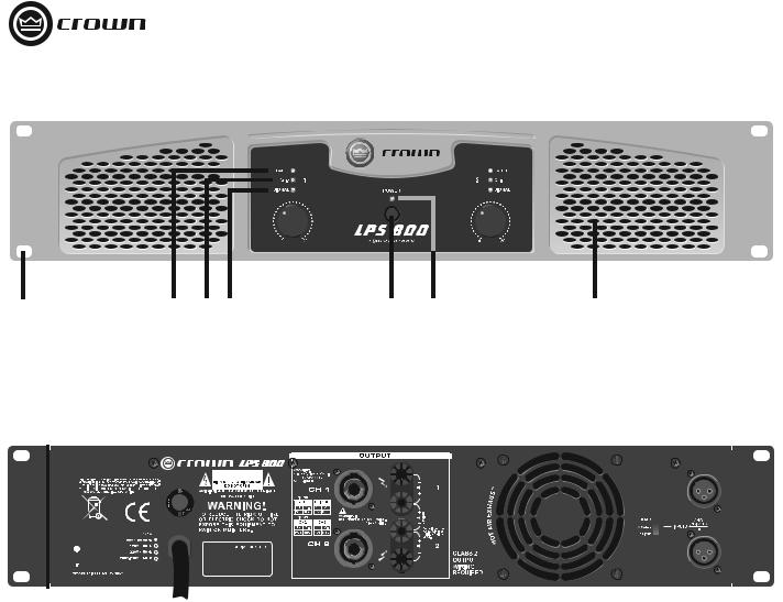
FRONT PANEL
1.Rack-mount hole (one of four)
2.Fault LED: Red LED, one per channel, indicates channel shutdown.
3.Clip LED: Red LED, one per channel, flashes when signal is audibly distorting.
4.Signal Presence LED: Green LED, one per channel, flashes when input signal exceeds -40 dBu.
5.Power Switch: Push-on, push-off.
6.Power LED: Blue LED illuminates when amplifier is on.
7. Volume Control: Sets output level of each channel.
8. Grille: Allows flow-through ventilation from front to back.
BACK PANEL
9.Reset Button: Resets the circuit breaker.
10.Power Cable: Permanently attached cable connects to AC mains power.
11.Output Connectors: One Speakon® per channel connects to loudspeakers.
12.Output Connectors: One pair binding posts per channel connects to loudspeakers.
13.Grille: Allows flow-through ventilation from front to back.
14. Output Mode Switch: Stereo (dual), Parallel or Bridge.
15. Input Connectors: Balanced XLR, one per channel.
page 4 |
Operation Manual |
LPS Series Power Amplifiers
Wiring
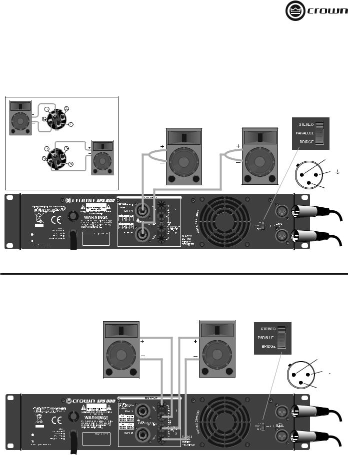
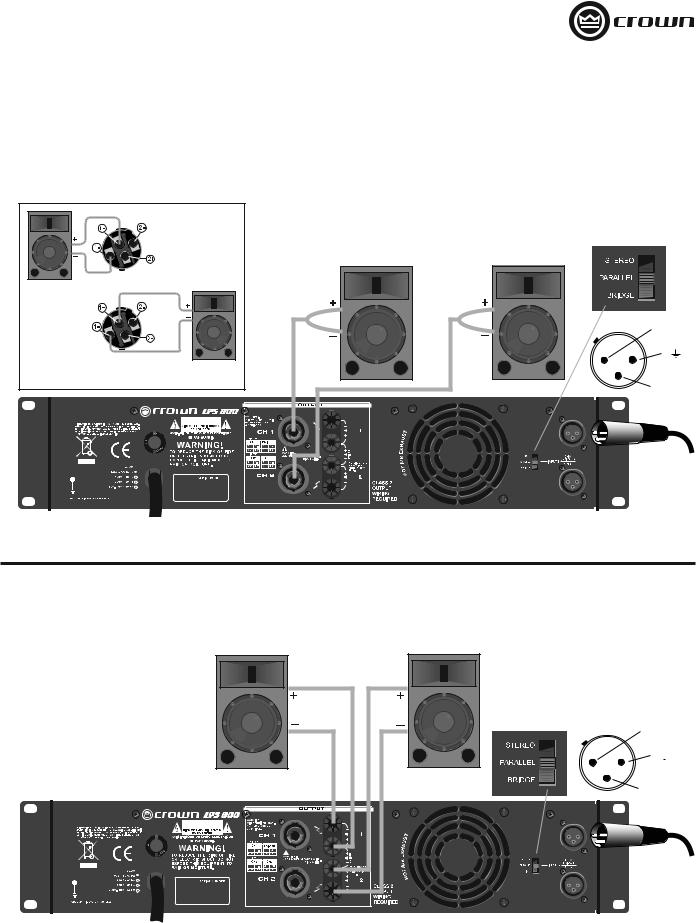
STEREO (DUAL) WIRING USING THE SPEAKON® CONNECTORS
1.See Figure 3. On the back panel, set the Output Mode Switch to STEREO.
2.Wire the speakers to the Speakon® connectors as shown.
|
Top Speakon® |
|
(Channel 1) |
Channel 1 |
|
Loudspeaker |
|
Bottom |
2 + |
Speakon® |
|
(Channel 2) |
1 |
Channel 2 |
|
Loudspeaker |
– |
3 |
|
Input signals |
|
Figure 3. Stereo (Dual) Wiring With Speakon® Connectors
STEREO (DUAL) WIRING USING THE BINDING POST CONNECTORS
1.See Figure 4. On the back panel, set the Output Mode Switch to STEREO.
2.Wire the speakers to the binding post connectors as shown.
2 +
1 
3 –
Input signals
Figure 4. Stereo (Dual) Wiring With Binding Post Connectors
Operation Manual |
page 5 |
LPS Series Power Amplifiers
Wiring
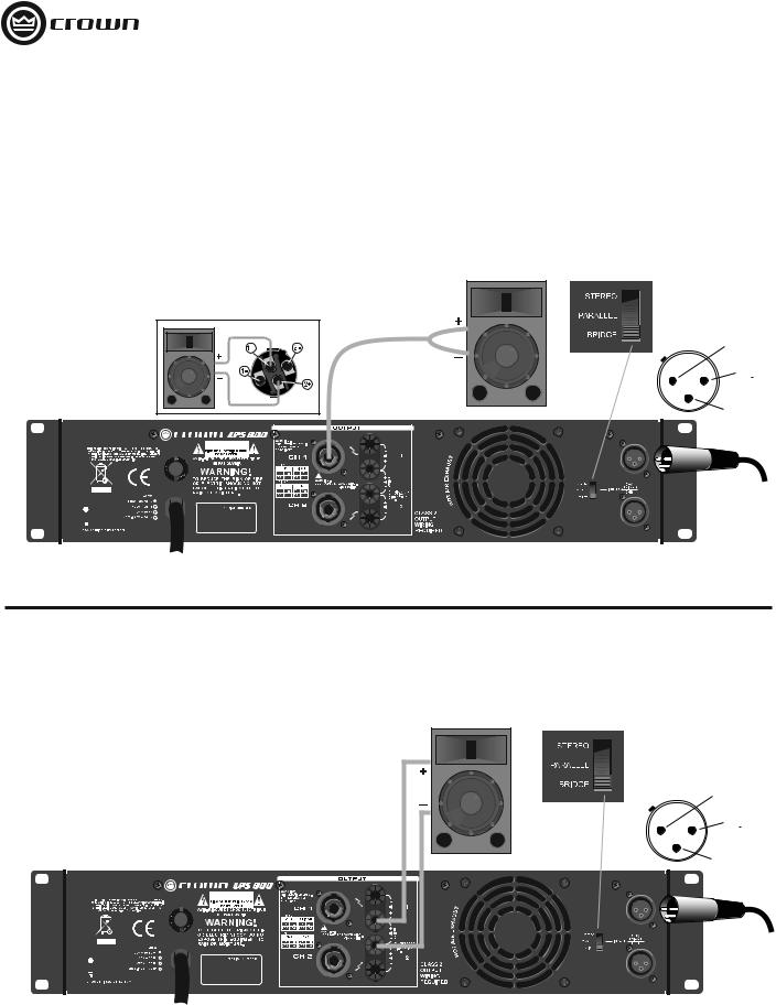
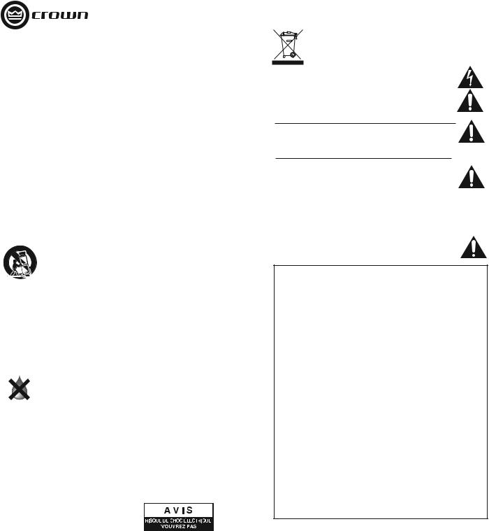
BRIDGE-MONO WIRING USING THE SPEAKON® CONNECTORS
Bridge-mono mode doubles the output power of the amplifier.
1.See Figure 5. On the back panel, set the Output Mode Switch to BRIDGE.
2.Wire the speaker to the Speakon® connector as shown.
3.Only the Channel 1 Volume Control works in Bridge-mono mode.
2 +
1 
3 –
Input signal
Figure 5. Bridge-Mono Wiring With Speakon® Connectors
BRIDGE-MONO WIRING USING THE BINDING POST CONNECTORS
Bridge-mono mode doubles the output power of the amplifier.
1.See Figure 6. On the back panel, set the Output Mode Switch to BRIDGE.
2.Wire the speaker to the Binding Post connectors as shown.
3.Only the Channel 1 Volume Control works in Bridge-mono mode.
2 +
1 
3 –
Input signal
Figure 6. Bridge-Mono Wiring With Binding Post Connectors
page 6 |
Operation Manual |
LPS Series Power Amplifiers
Wiring
PARALLEL WIRING USING THE SPEAKON® CONNECTORS
With this wiring, a signal sent to Channel 1 is paralleled to both channels so that it is reproduced by both speakers.
1.See Figure 7. On the back panel, set the Output Mode Switch to PARALLEL.
2.Wire the speakers to the Speakon® connectors as shown.
Top Speakon (Channel 1)
Channel 1
Loudspeaker
Bottom |
2 + |
|
|
|
|
Speakon |
|
1 |
(Channel 2) |
Channel 2 |
|
|
|
|
|
Loudspeaker |
– |
|
3 |
|
|
Input signal |
|
Figure 7. Parallel Wiring With Speakon® Connectors
PARALLEL WIRING USING THE BINDING POST CONNECTORS
With this wiring, a signal sent to Channel 1 is paralleled to both channels so that it is reproduced by both speakers.
1.See Figure 8. On the back panel, set the Output Mode Switch to PARALLEL.
2.Wire the speakers to the binding post connectors as shown.
2 +
1 
3 –
Input signal
Figure 8. Parallel Wiring With Binding Post Connectors
Operation Manual |
page 7 |

LPS Series Power Amplifiers
Specifications
Guaranteed Minimum Power |
LPS-800 |
|
LPS-1500 |
|
LPS-2500 |
|
|
|
|
|
|
1 kHz (EIA) with 0.5% THD |
|
|
|
|
|
4 ohms stereo (per channel) |
300W |
|
400W |
|
725W |
8 ohms stereo (per channel) |
150W |
|
250W |
|
550W |
8 ohms bridge mono |
600W |
|
800W |
|
1450W |
|
|
|
|
|
|
Performance |
|
|
|
|
|
|
|
|
|
|
|
Frequency Reponse (at 1 watt) |
|
40 Hz - 20 kHz, +0/–3 dB |
|
||
|
|
|
|
||
Total Harmonic Distortion (THD) |
|
< 0.5%, 20 Hz - 20 kHz |
|
||
|
|
|
|
|
|
Intermodulation Distortion (IMD) |
|
< 0.3% |
|
|
|
60 Hz and 7 kHz at 4:1, from full rated output to –30 dB |
|
|
|
||
|
|
|
|
|
|
Slew Rate |
> 20V/μs |
|
> 23V/μs |
|
> 27V/μs |
|
|
|
|
|
|
Voltage Gain |
32 dB |
|
32 dB |
|
34 dB |
|
|
|
|
|
|
Damping Factor (8 ohms), 10 Hz - 400 Hz |
|
> 300 |
|
|
|
|
|
|
|
|
|
Signal-to-Noise Ratio (below rated power, 20 Hz to 20 kHz, A-weighted |
|
|
> 100 dB |
|
|
|
|
|
|
|
|
Crosstalk (below rated power) |
|
|
|
|
|
At 1 kHz |
|
|
–76 dB |
|
|
At 20 kHz |
|
|
–58 dB |
|
|
Input Sensitivity for full rated power at 4 ohms |
|
|
1.25V rms |
|
|
|
|
|
|
|
|
Input Impedance (nominal) |
|
|
|
|
|
Balanced |
|
|
20 kilohms |
|
|
Unbalanced |
|
|
10 kilohms |
|
|
|
|
|
|
|
|
Connectors, Controls and Indicators |
|
|
|
|
|
|
|
||||
Input Connectors |
One balanced XLR for each channel |
||||
|
|
||||
Output Connectors (Speaker Connectors) |
Speakon® and one pair binding post for each channel |
||||
Front Panel Controls |
Power on/off switch, one gain control per channel |
||||
|
|
||||
Rear Panel Controls |
Output mode switch: stereo (dual), parallel or bridge |
||||
|
|
|
|
|
|
Power Indicator |
|
|
One blue LED |
|
|
|
|
|
|
||
Signal Indicator |
|
One green LED per channel |
|
||
|
|
|
|
||
Clip (peak) Indicator |
|
One red LED per channel |
|
||
|
|
||||
Fault Indicator |
Red LED, one per channel, indicates channel shutdown |
||||
|
|
|
|
|
|
Construction |
|
|
|
|
|
Protection |
Protection against short circuits, no-load, on/off muting, RF |
||||
|
interference. Stable into reactive or mismatched loads |
||||
|
|
||||
Ventilation |
Flow-through ventilation from front to back |
||||
|
|
||||
Cooling |
Internal heat sinks with forced air. Fan cooled, speed regulated, |
||||
|
thermal protection |
|
|||
Dimensions (W x H x D) |
19" x 3.5" x 15.2" (482 mm x 89 mm x 386 mm) |
||||
|
|
|
|
|
|
Net Weight |
20.9 lb (9.5 kg) |
|
22.9 lb (10.4 kg) |
|
29.8 lb (13.5 kg) |
|
|
|
|
|
|
Shipping Weight |
24.0 lb (10.9 kg) |
|
26.0 lb (11.8 kg) |
|
32.8 lb (14.9 kg) |
|
|
|
|
|
|
page 8 |
Operation Manual |

LPS Series Power Amplifiers
Warranty
ONE YEAR LIMITED WARRANTY
SUMMARY OF WARRANTY
Crown International, 1718 West Mishawaka Road, Elkhart, Indiana 46517-4095 U.S.A. warrants to you, the ORIGINAL PURCHASER and ANY SUBSEQUENT OWNER of each NEW Crown product, for a period of one (1) year from the date of purchase by the original purchaser (the “warranty period”) that the new Crown product is free of defects in materials and workmanship. We further warrant the new Crown product regardless of the reason for failure, except as excluded in this Warranty.
Warranty is only valid within the country in which the product was purchased.
ITEMS EXCLUDED FROM THIS CROWN WARRANTY
This Crown Warranty is in effect only for failure of a new Crown product which occurred within the Warranty Period. It does not cover any product which has been damaged because of any intentional misuse, accident, negligence, or loss which is covered under any of your insurance contracts. This Crown Warranty also does not extend to the new Crown product if the serial number has been defaced, altered, or removed.
WHAT THE WARRANTOR WILL DO
We will remedy any defect, regardless of the reason for failure (except as excluded), by repair, replacement, or refund. We may not elect refund unless you agree, or unless we are unable to provide replacement, and repair is not practical or cannot be timely made. If a refund is elected, then you must make the defective or malfunctioning product available to us free and clear of all liens or other encumbrances. The refund will be equal to the actual purchase price, not including interest, insurance, closing costs, and other finance charges less a reasonable depreciation on the product from the date of original purchase. Warranty work can only be performed at our authorized service centers or at the factory. Warranty work for some products can only be performed at our factory. We will remedy the defect and ship the product from the service center or our factory within a reasonable time after receipt of the defective product at our authorized service center or our factory. All expenses in remedying the defect, including surface shipping costs in the United States, will be borne by us. (You must bear the expense of shipping the product between any foreign country and the port of entry in the United States including the return shipment, and all taxes, duties, and other customs fees for such foreign shipments.)
HOW TO OBTAIN WARRANTY SERVICE
You must notify us of your need for warranty service within the warranty period. All components must be shipped in a factory pack, which, if needed, may be obtained from us free of charge. Corrective action will be taken within a reasonable time of the date of receipt of the defective product by us or our authorized service center. If the repairs made by us or our authorized service center are not satisfactory, notify us or our authorized service center immediately.
DISCLAIMER OF CONSEQUENTIAL AND INCIDENTAL DAMAGES
YOU ARE NOT ENTITLED TO RECOVER FROM US ANY INCIDENTAL DAMAGES RESULTING FROM ANY DEFECT IN THE NEW CROWN PRODUCT. THIS INCLUDES ANY DAMAGE TO ANOTHER PRODUCT OR PRODUCTS RESULTING FROM SUCH A DEFECT. SOME STATES DO NOT ALLOW THE EXCLUSION OR LIMITATIONS OF INCIDENTAL OR CONSEQUENTIAL DAMAGES, SO THE ABOVE LIMITATION OR EXCLUSION MAY NOT APPLY TO YOU.
WARRANTY ALTERATIONS
No person has the authority to enlarge, amend, or modify this Crown Warranty. This Crown Warranty is not extended by the length of time which you are deprived of the use of the new Crown product. Repairs and replacement parts provided under the terms of this Crown Warranty shall carry only the unexpired portion of this Crown Warranty.
DESIGN CHANGES
We reserve the right to change the design of any product from time to time without notice and with no obligation to make corresponding changes in products previously manufactured.
LEGAL REMEDIES OF PURCHASER
THIS CROWN WARRANTY GIVES YOU SPECIFIC LEGAL RIGHTS, YOU MAY ALSO HAVE OTHER RIGHTS WHICH VARY FROM STATE TO STATE. No action to enforce this Crown Warranty shall be commenced after expiration of the warranty period.
THIS STATEMENT OF WARRANTY SUPERSEDES ANY OTHERS CONTAINED IN THIS MANUAL FOR CROWN PRODUCTS. 09/07
Operation Manual |
page 9 |

Manuel d'utilisation
LPS-800 |
LPS-1500 |
LPS-2500 |
Versions dans d'autres langues: Pour obtenir des informations concernant l'utilisation de ce produit dans d'autres langues, veuillez contacter votre distributeur Crown local. Si vous avez besoin d'aide pour localiser votre distributeur local, veuillez contacter Crown au 574-294-8000.
Ce manuel n'inclut pas tous les détails de conception, production ou variations de l'équipement. Il ne couvre également pas toutes les situations possibles pouvant survenir au cours de l'installation, de l'exploitation ou de l'entretien.
Les informations figurant dans ce manuel sont considérées comme exactes à la date de publication. Toutefois, des mises à jour de ces informations sont peut-être survenues. Pour obtenir la dernière version de ce manuel, visitez le site web de Crown www.crownaudio.com
Avis concernant les marques déposées: Crown and Crown Audio sont des marques déposées de Crown International. Les autres marques de commerce appartiennent à leurs propriétaires respectifs.
©2008 by Crown Audio®, Inc., 1718 W. Mishawaka Rd., Elkhart, Indiana 46517-9439 U.S.A. Téléphone :574-294-8000
140481-4 5/09
LPS Series Power Amplifiers
Crown International, Inc.
DECLARATION DE CONFORMITE
Publiée par : |
Crown International, Inc. |
|
1718 W. Mishawaka Road |
|
Elkhart, Indiana 46517 |
|
U.S.A. |
Nom et adresse du représentant européen :
David Budge
10 Harvest Close
Yateley GU46 6YS
Royaume-Uni
Type d'équipement : Amplificateurs de puissance audio du commerce
Nom de la famille de produits : LPS
Noms des modèles : LPS-800, LPS-1500, LPS-2500
Normes EMC :
QUESTIONS DE CONFORMITE UNIQUEMENT : |
Sue Whitfield |
|
574-294-8289 |
|
swhitfield@crownintl.com |
EN 55103-1:1997 Compatibilité électromagnétiqueNorme de famille de produits pour les appareils Audio, Vidéo, Audio-Visuels et Divertissement Appareil de contrôle de l'éclairage à usage professionnel, Partie 1: Emissions
EN 55103-1:1997 Emissions de champ magnétique-Annexe A @ 10 cm et 20 cm
EN 61000-3-2:2001 Limites des émissions du courant harmonique (courant d'entrée de l'équipement inférieur ou égal à 16 A par phase)
EN 61000-3-3:2002 Limites des fluctuations de tension et flicker dans les systèmes d'alimentation basse tension Courant nominal inférieur ou égal à 16A
EN 55022:2003 Limites et méthodes de mesure des caractériques de perturbation radioélectrique d'ITE : Rayonnement, Limites Classe B; Conduit, Classe A
EN 55103-2:1997 Compatibilité électromagnétiqueNorme de famille de produits pour les appareils Audio, Vidéo, Audio-Visuels et Divertissement Appareil de contrôle de l'éclairage à usage professionnel, Partie 2 : Immunité
EN 61000-4-2:2001 Immunité de décharge électrostatique (Environnement E2-Critère B, 4k V Contact, Evacuation d'air 8k V)
EN 61000-4-3:2001 Rayonnement, Fréquence radio, Immunité électromagnétique (Environnement E2, critère A)
EN 61000-4-4:2001 Transitoire électrique rapide/Immunité aux explosions (Critère B)
EN 61000-4-5:2001 Immunité surtension (Critère B)
EN 61000-4-6:2003 Immunité aux perturbations conduites induites par champs radioélectriques (Critère A)
EN 61000-4-11:2001 Baisses de tension, Interruptions courtes et Variation de tension
Norme de sécurité :
IEC 60065: 2001 7e Ed. Exigences de sécurité - Audio, Vidéo et appareils électroniques similaires
Je certifie que le produit identifié ci-dessus est conforme aux exigences de la Directive du conseil de l'EMC 89/336/CEE telle que modifiée par 92/31/CEE, et à la Directive basse tension 73/23/EES telle que modifiée par 93/68/CEE.
Signé par _____________________
Andrew Stump
Titre : Vice président senior de la Fabrication
En raison des harmoniques du courant, nous vous recommandons de contacter votre fournisseur d'électricité avant tout raccordement. En raison des harmoniques du courant, nous vous recommandons de contacter votre compagnie d’électricité avant connexion.
Date de publication : 1er juillet 2008
Operation Manual |
page 11 |
Instructions importantes relatives à la sécurité
1.Veuillez lire ces instructions.
2.Veuillez conserver ces instructions.
3.Respectez tous les avertissements.
4.Suivez toutes les instructions.
5.Ne pas utiliser cet appareil à proximité de l'eau.
6.Nettoyer exclusivement au moyen d'un linge sec.
7.Ne pas bloquer des ouvertures de ventilation. Installer conformément aux instructions du fabricant.
8.Ne pas installer à proximité de sources de chaleur telles que des radiateurs, registres de chaleur ou autre appareil (dont des amplificateurs) qui produisent de la chaleur.
9.Ne pas contrevenir à la sécurité de la fiche polarisée ou de type terre. Une fiche polarisée est munie de deux lames dont l'une est plus large que l'autre. Une fiche polarisée est munie de deux lames et d'une broche de raccordement à la terre. La lame large ou la troisième broche est installée pour optimiser votre sécurité. Si la fiche fournie ne correspond pas à votre prise, consultez un électricien en vue de faire remplacer la prise obsolète.
10.Assurez-vous que personne ne marche sur le cordon d'alimentation ou qu'il est pas pincé, en particulier sur les prises, prises de courant et à l'endroit où il sort de l'appareil.
11.Utiliser exclusivement les accessoires spécifiés par le fabricant.
12. Utiliser uniquement avec un chariot, tripode, console ou table spécifiés par le fabricant ou vendus avec l'appareil. En cas d'utilisation d'un chariot, prendre des précautions lorsque vous déplacez le chariot /appareil pour éviter toute blessure due à une chute.
13.Débranchez cet appareil au cours des orages ou si vous ne l'utilisez pas pendant une durée prolongée.
14.Confiez tout l'entretien à un personnel d'entretien qualifié. Un entretien est nécessaire lorsque l'appareil a été endommagé, par exemple, si le cordon d'alimentation ou la fiche sont endommagés, si du liquide a été projeté sur l'appareil ou si des objets sont tombés dans l'appareil, si l'appareil a été exposé à la pluie ou à l'humidité, ne fonctionne pas correctement ou est tombé.
15.Utilisez la fiche principale pour débrancher l'appareil du secteur.
16.AVERTISSEMENT : POUR REDUIRE LE RISQUE D'INCENDIE OU
DE DECHARGE ELECTRIQUE, NE PAS EXPOSER L'APPAREIL A LA
PLUIE OU A L'HUMIDITE.
17.NE PAS EXPOSER CET EQUIPEMENT A DES GOUTTES OU A DES PROJECTIONS D'EAU ET S'ASSURER QU'AUCUN OBJET REMPLI DE LIQUIDE, TEL QU'UN VASE, N'EST PLACE SUR L'EQUIPEMENT.
18.LA FICHE PRINCIPALE DU CORDON D'ALIMENTATION DOIT RESTER EXPLOITABLE A TOUT MOMENT.
POUR PRÉVENIR LES DÉCHARGES ÉLECTRIQUES, NE PAS RETIRER LES CAPOTS INFÉRIEURS OU SUPÉRIEURS. AUCUNE PIÈCE SUSCEPTIBLE D'ÊTRE ENTRETENUE PAR L'UTILISATEUR NE SE TROUVE À L'INTÉRIEUR. CONFIEZ TOUT L'ENTRETIEN À UN PERSONNEL D'ENTRETIEN QUALIFIÉ.
POUR DEBRANCHER INTEGRALEMENT CET EQUIPEMENT DU COURANT CA, DEBRANCHEZ LE CORDON D'ALIMENTATION DE LA PRISE CA. LA FICHE PRINCIPALE DU CORDON D'ALIMENTATION DOIT RESTER EXPLOITABLE A TOUT MOMENT.
Introduction
Félicitations pour votre achat d'un amplificateur de puissance Crown® LPS. Les trois modèles de la série sont puissants, solides et fiables. Ils
sont conçus pour les applications telles que les églises, tournées de concert, scènes, boîtes de nuit, bars ou tout endroit nécessitant l'installation d'un amplificateur.
Les caractéristiques comprennent des entrées XLR, sorties Speakon® et à bornes, mode stéréo/parallèle/bridge-mono, voyant de fonctionnement/ défaut/signal/clip, ventilation à air forcé, protection contre les courtscircuits, circuit ouvert, silencieux on/off et interférence des ondes radio.
page 12
LPS Series Power Amplifiers
FAITES ATTENTION A CES SYMBOLES : Le triangle contenant un éclair permet d'alerter l'utilisateur du risque de décharge électrique.
Le triangle contenant un point d'exclamation sert à alerter l'utilisateur d'instructions d'exploitation ou de maintenance importantes.
IMPORTANT
Les amplificateurs de la Série LPS nécessitent un câblage de sortie de Classe 2..
CHAMPS MAGNÉTIQUES
ATTENTION ! Ne pas installer des équipements sensibles à gain élevé tels que des préamplificateurs ou des platines de magnétophone au-dessus ou en dessous de l'unité. Cet amplificateur étant doté d'une densité électrique élevée, son champ magnétique élevé peut générer des bourdonnements sur les dispositifs non blindés situés à proximité. Le champ est plus important juste au-dessus et en dessous de l'unité.
Si un rack d'équipements est utilisé, nous recommandons d'installer le ou les amplificateurs en bas du rack et le préamplificateur ou autre équipement sensible en haut du rack.
Prévoir un espace standart de montage de rack de deux pouces sur chaque côté et de 5cm à l'arrière.
AVIS DE CONFORMITE FCC
Ce dispositif est conforme à la partie 15 des Réglementations FCC. L'exploitation est soumise aux deux conditions suivantes : (1) Ce dispositif ne doit pas provoquer d'interférences dangereuses et (2) ce dispositif doit accepter toute interférence reçue, dont les interférences pouvant générer un fonctionnement non souhaité.
ATTENTION : Les modifications non expressément approuvées par la partie responsable de la conformité peuvent annuler le permis d'exploitation de l'équipement de l'utilisateur.
REMARQUE : Cet équipement a été testé et est conforme aux limites d'un dispositif numérique de Classe B, conformément à la partie 15 des Réglementations FCC. Ces limites sont conçues pour fournir une protection raisonnable contre les interférences dangereuses dans une installation résidentielle. Cet équipement génère, utilise et peut irradier de l'énergie de fréquence radio et, s'il n'est pas installé conformément au manuel d'instructions, peut provoquer des interférences dangereuses sur les communications radio. Toutefois, il n'est pas garanti qu'aucune interférence ne va survenir dans une installation particulière. Si cet équipement provoque des interférences dangereuses sur la réception de la radio ou de la télévision, ce qui peut être déterminé en éteignant et en allumant l'équipement, l'utilisateur est encouragé
à tenter de corriger l'interférence au moyen de l'une ou de plusieurs des mesures suivantes :
ss2£ORIENTEZ OUED£PLACEZ LgANTENNE DEPR£CEPTION ss!UGMENTEZMLA DISTANCE ENTRE Lg£QUIPEMENT ETELE R£CEPTEUR
ss2ACCORDEZCLg£QUIPEMENT Ü UNE SORTIEPSURMUN CIRCUIT DIFF£RENT DE CELUI AUQUELILE A récepteur est raccordé.
ss$EMANDEZ Ü VOTRE FOURNISSEUR LES COORDONN£ES DgUNSTECHNICIEN 46 2ADIO EXP£RIO menté pour obtenir de l'aide.
Installation
Conçue pour être installée dans un rack d'équipements standard 19 pouces, l'unité n'occupe que deux espaces de rack. Fixez l'unité avec les quatres vis de montage en rack et les rondelles à collerette. Pour un refroidissement optimal, installez les amplificateurs sans espace prévu entre les éléments. Si les amplificateurs sont installés en rack avec des espaces, des panneaux de rack solides non ventilés sont recommandés entre les amplificateurs. Prévoir un espace standart de montage de rack de deux pouces sur chaque côté et de 5cm à l'arrière.
Cette unité est fournie avec un ventilateur à vitesse variable qui règle automatiquement la vitesse du ventilateur en fonction de la température de l'unité pendant le fonctionnement. Le débit de l'air va de l'avant vers l'arrière, ne pas placer d'objet susceptibles d'empêcher l'air de sortir de l'unité depuis sa ventilation arrière..
Operation Manual
 Loading...