


‘TOTAL PERFORMAN CE IS WHAT COUNTS"
CROWN test and check-out procedures reflect our basic design philosophy; we believe that reliability can be engineered into a product. As such, our check-out is designed to expose and
correct a problem, before it happens. This testing begins when
the unit is still a pile of parts; grading and selection of
components is |
standard. The final test-inspection is the culmina- |
|||||
tion of this vigorous program, but our concern doesn’t |
stop here. |
|||||
Our |
products |
are |
backed by an extensive field |
service program, |
||
and |
protected |
by |
a comprehensive |
warranty. |
|
|
A word about |
our |
testing procedure |
is in order. |
All |
our specifi- |
|
cations are referenced to an AC input of 120 VAC. The high
current demand with high power tends to cause the line voltage
to sag, or the sinusoidal waveform to distort. With a distorted waveform (or lower line voltage) the peak voltage is lowered. Since it is the peaks that charge the filter capacitors in the amplifier power supply, and thus determine the maximum power output, a line voltage problem reduces the maximum power output. CROWN uses a peak equivalent AC voltmeter which measures the peaks of any waveform and converts this to an
equivalent |
rms reading |
for |
a |
sinusoidal |
waveform. |
This |
way we |
can vary |
or regulate |
the |
line |
voltage, |
no matter |
how |
distorted |
the waveform, to an equivalent of a 120 VAC sinewave. We are then measuring a true maximum output power.
With regard to the precision load which we use for our testing,
we realize that a resistive load is quite different than a reactive speaker. However, using readily available parts, a precision resistive load is the easiest to duplicate, with respect to obtaining consistent results. We specify that the load must be resistive, having less than 10% reactive component at any frequency up to five times the highest test frequency. The
resistance value should be maintained within 1%, at all power levels.
The following discussion examines each of the test procedures listed on the facing page. This is an attempt to help you understand, in layman’s terms, what the tests mean.
Quiescent Offset - This simply assures t h a t y o u r
amplifier’s output is balanced with reference to its input.
Thus the amplifier will not “bias” the program with a
dc component. To meet specifications, offset must be less than 10 mv.
1KHz - This test measures the power across an 8 ohm load at a frequency of 1 KHz with both channels operating.
This is a determination of how |
much |
power |
an amplifier |
|
can produce before a specified |
total |
harmonic |
distortion |
|
is reached. For the DC-300A, |
the |
power |
is |
180 watts |
at less than .1% T H D . |
|
|
|
|
4 Ohm Test - This is a critical examination of the DC-300’s performance at impedances below that for which it is rated. We check the wave form for level (it must reach a specified voltage before clipping) purity, and stability.
4.Protection Test - This is a test with a 2 ohm load which
|
determines |
the |
threshold at which the protection |
circuitry |
|
|
will be activated. Sharp clipping should occur with no |
||||
|
evidence of instability. The positive and negative limiters |
||||
|
operated independently and therefore may not be activated |
||||
|
simultaneously. |
|
|
||
5. |
Reliability |
Test |
- This test puts the output stages through |
||
|
an extremely vigorous thermal cycling. The test is a very |
||||
|
low frequency input signal driving the output to full |
||||
|
power across a short circuit for a predetermined period of |
||||
|
time. |
|
|
|
|
6. |
20KHz - |
This tests the amplifier at its rated power level. |
|||
|
We specify that at any frequency between 1Hz and |
||||
|
2OKHz |
the DC-300A will produce 155 watts |
minimum |
||
|
rms (both channels operating) into an 8 ohm load, at a |
||||
|
sum total |
harmonic distortion of .05% or less. We choose |
|||
|
20KHz |
as the |
test frequency because high frequencies |
||
|
produce more heat than lower frequencies. Thus, if the |
||||
|
amplifier can safely pass the 20KHz test, it will operate |
||||
|
safely |
at |
lower |
frequencies. |
|
7.10 KHz Square Wave - This test critically examines the amplifier’s frequency response and rise time. (How fast the amplifier can follow rapid signal changes.) The output square wave (with an 8 ohm load) should be clean and
|
sharp, |
with no ringing |
or |
overshoot. |
|
|||||
8. |
Mono |
Operation |
- This is |
a |
check for proper operation |
of |
||||
|
the stereo mono switch. A signal is applied to channel 1 |
|||||||||
|
input only and the mono output |
is observed between |
the |
|||||||
|
two |
red |
output |
terminals |
of |
the |
amplifier. |
|
||
9. |
IM |
Distortion |
Test |
- A t |
C R O W N w e f e e l t h a t |
I M |
||||
|
distortion testing yields a truer picture of amplifier |
|||||||||
|
performance than harmonic distortion testing. While a |
|||||||||
|
large amount of documentation supports this opinion, |
|||||||||
|
some of the reasons are apparent, even in layman’s terms. |
|||||||||
|
For example, a sinusoidal waveform (used in HD testing) |
|||||||||
|
bears little resemblance to the complex waveforms |
|||||||||
|
associated with actual program materials. IMD testing |
|||||||||
|
uses |
such a complex |
waveform. |
Also, harmonic distortion |
||||||
|
is not always aurally offensive. The human ear may |
|||||||||
|
interpret such distortion as pleasing, but usually finds IM |
|||||||||
|
distortion rather obnoxious. In order to support this |
|||||||||
|
design philosophy, we designed and built our own IM |
|||||||||
|
analyzer |
with residual |
noise |
and |
distortion low enough |
to |
||||
|
test |
our |
amplifiers. |
|
|
|
|
|
||
10.Hum and Noise - This test, in plain English, tells you how
small |
a signal can be |
amplified |
without |
it becoming “lost |
|
in the |
mud”. The |
test |
is limited |
to the audio band width |
|
of 20Hz-20KHz, |
with a bandpass |
filter. |
Our specification |
||
for the DC-300A is: hum and noise from 20Hz - 20KHz will be at least 110db below the full power output of 155
watts. This means that with |
a 155 |
watt output |
the noise |
|
will |
be only .00155 micro |
watts. |
(That’s 1.55 |
billionths |
of a |
watt ) |
|
|
|
11.Quiescent AC power Input at 120 VAC - This test
confirms that your amplifier is not drawing excessive power while “idling”. If an amplifier exhibits a tendency
toward instability, or |
oscillation, it may draw power with |
|
no |
signal input. The |
DC-300A will draw 40 watts or less |
at |
idle. |
|
|
|
TABLE OF CONTENTS |
|
|
|
|
PAGE |
Section 1 |
DESCRIPTION |
|
|
1 .1 |
General . . . . . . . . . |
. . . . . . . . . . . . . . . . . . . . . . . . . . . . . . . . . . . . . . . . . . . . . . . . . . . . . . . . . . . . . . . . . . . . . . . . . . . . . . . . . . . . . . . . . . . . . . . . . . . . . . . . . . |
. . . . . . . . . . . 1 |
1.2 |
Specifications |
. . . . . . . . . . . . . . . . . . . . . . . . . . . . . . . . . . . . . . . . . . .. . . . . . . . . . . . . . . . . . . . . . . . . . . . . . . . . . . . . . . . . . . . . . . . . . . . . . . . . . . . . |
2, 3, 4, 5 |
1 .3 |
Warranty . . . . . . . |
. . . . . . . . . . . . . . . . . . . . . . . . . . . . . . . . . . . . . . . . . . . . . . . . . . . . . . . . . . . . . . . . . . . . . . . . . . . . . . . . . . . . . . . . . . . . . . . . . . . . . . . . . . . |
. . . . . . ... 12 |
Section 2 |
INSTALLATION |
|
|
2.1 |
Unpacking . . . . . |
. . . . . . . . . . . . . . . . . . . . . . . . . . . . . . . . . . . . . . . . . . . . . . . . . . . . . . . . . . . . . . . . . . . . . . . . . . . . . . . . . . . . . . . . . . . . . . . . . . . . . . . . . . . |
. . . . . . . .. 13 |
2.2 |
Mounting . . . . . . |
. . . . . . . . . . . . . . . . . . . . . . . . . . . . . . . . . . . . . . . . . . . . . . . . . . . . . . . . . . . . . . . . . . . . . . . . . . . . . . . . . . . . . . . . . . . . . . . . . . . . . . . . . . . |
. . . . . . .. . 13 |
2.3 |
Normal Hi-Fi Installation . . . . . . . . . . . . . . . . . . . . . . . . . . . . . . . . . . . . . . . . . . . . . . . . . . . . . . . . . . . . . . . . . . . . . . . . . . . . . . . . . . . . . . . . |
. . . . . . . . . . .13 |
|
2.4 |
Connecting Output Lines ................................................................................................ |
, 14 |
|
|
|
|
16 |
2.4.1 |
Mono Operation . . . . . . . . . . . . . . . . . . . . . . . . . . . . . . . . . . . . . . . . . . . . . . . . . . . . . . . . . . . . . . . . . . . . . . . . . . . . . . . . . . . . . . . . . . . . . . . . . . . . . . . |
. . . . . . . . . . |
|
2.5 |
Connecting Input Lines . . . . . . . . . . . . . . . . . . . . . . . . . . . . . . . . . . . . . . . . . . . . . . . . . . . . . . . . . . . . . . . . . . . . . . . . . . . . . . . . . . . . . . . . . . . |
. . . . . . . . . .16 |
|
2.6 |
Connecting Power . . . . . . . . . . . . . . . . . . . . . . . . . . . . . . . . . . . . . . . . . . . . . . . . . . . . . . . . . . . . . . . . . . . . . . . . . . . . . . . . . . . . . . . . . . . . . . . . . . . . |
. . . . . . . . . .17 |
|
Section 3 OPERATING INSTRUCTIONS |
|
||
3.1 |
Controls and |
Adjustments . . . . . . . . . . . . . . . . . . . . . . . . . . . . . . . . . . . . . . . . . . . . . . . . . . . . . . . . . . . . . . . . . . . . . . . . . . . . . . . . . . . . . . . |
. . . . . . . . . .19 |
3.2 |
The Protection |
Mechanisms . . . . . . . . . . . . . . . . . . . . . . . . . . . . . . . . . . . . . . . . . . . . . . . . . . . . . . . . . . . . . . . . . . . . . . . . . . . . . . . . . . . |
. . . . . . . 19 |
|
|
|
21 |
3.3 |
Operating Precautions . . . . . . . . . . . . . . . . . . . . . . . . . . . . . . . . . . . . . . . . . . . . . . . . . . . . . . . . . . . . . . . . . . . . . . . . . . . . . . . . . . . . . . . . . . . . . |
. . . . . . . . . . |
|
3.4 |
Load Protection Methods . . . . . . . . . . . . . . . . . . . . . . . . . . . . . . . . . . . . . . . . . . . . . . . . . . . . . . . . . . . . . . . . . . . . . . . . . . . . . . . . . . . . . . . . |
. . . . . . . . . .21 |
|
3.5 |
Cleaning . . . . . . . . |
. . . . . . . . . . . . . . . . . . . . . . . . . . . . . . . . . . . . . . . . . . . . . . . . . . . . . . . . . . . . . . . . . . . . . . . . . . . . . . . . . . . . . . . . . . . . . . . . . . . . . . . . . . . . |
. . . . . . . 22 |
Section 4 |
CIRCUITRY |
|
|
4.1 |
Principles of Operation . . . . . . . . . . . . . . . . . . . . . . . . . . . . . . . . . . . . . . . . . . . . . . . . . . . . . . . . . . . . . . . . . . . . . . . . . . . . . . . . . . . . . . . . . . . . |
. . . . . . . . . .23 |
|
|
|
|
24 |
4.2 |
Test Procedures . . . . . . . . . . . . . . . . . . . . . . . . . . . . . . . . . . . . . . . . . . . . . . . . . . . . . . . . . . . . . . . . . . . . . . . . . . . . . . . . . . . . . . . . . . . . . . . . . . . . . . . |
. . . . . . . . . . |
|
4.3 |
Service . . . . . . . . . . |
. . . . . . . . . . . . . . . . . . . . . . . . . . . . . . . . . . . . . . . . . . . . . . . . . . . . . . . . . . . . . . . . . . . . . . . . . . . . . . . . . . . . . . . . . . . . . . . . . . . . . . . . . . . . . . . ...... |
24 |
Section 5 |
APPLICATION NOTES |
|
|
|
Application Note No. 1 - V-l Limits of a Load . . . . . . . . . . . . . . . . . . . . . . . . . . . . . . . . . . . . . . . . . . . . . . . . . . . . . . |
. . . . . . . . . 25 |
|
|
Application Note No. 2 - VFX-2 . . . . . . . . . . . . . . . . . . . . . . . . . . . . . . . . . . . . . . . . . . . . . . . . . . . . . . . . . . . . . . . . . . . . . . . . . . . . |
. . . . . . . . . .27 |
|
|
Application Note No. 3 - Speaker Protection . . . . . . . . ....................................................... |
29 |
|
LIST OF ILLUSTRATIONS
TITLE
l - l l-2
|
|
PAGE |
DC-300A Pictorial . . . . . . . . . . . . . . . . . . . . . . . . . . . . . . . . . . . . . . . . . . . . . . . . . . . . . . . . . . . . . . . . . . . . . . . . . . . . . . . . . . . . . . . . . |
. . . . . . . . . . . . . . . |
. . . . . . . .1 |
DC-300A Performance Graphs |
|
5 |
I.M. Distortion . . . . . . . . . . . . . . . . . . . . . . . . . . . . . . . . . . . . . . . . . . . . . . . . . . . . . . . . . . . . . . . . . . . . . . . . . . . . . . . . . . . . . . . . . . . . . . . |
. . . . . . . . . . . . . . . |
|
Harmonic Distortion . . . . . . . . . . . . . . . . . . . . . . . . . . . . . . . . . . . . . . . . . . . . . . . . . . . . . . . . . . . . . . . . . . . . . . . . . . . . . . . . . . . . . . . |
. . . . . . . . . . . . . . |
. . . . . . . .5 |
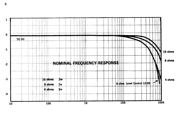
Frequency Response . . . . . . . . . . . . . . . . . . . . . . . . . . . . . . . . . . . . . . . . . . . . . . . . . . . . . . . . . . . . . . . . . . . . . . . . . . . . . . . . . . . . . . |
. . . . . . . . . . . . . . |
. . . . . . . .6 |
Power Response |
|
6 |
. . . . . . . . . . . . . . |
. . . . . . . .7 |
|
Phase Response |
|
|
. . . . . . . . . . . . . . |
. . . . . . . .8 |
|
Noise Spectrum |
|
|
. . . . . . . . . . . . . . |
. . . . . . . .8 |
|
Crossta Ik . . . . . . . . . . . . . . . . . . . . . . . . . . . . . . . . . . . . . . . . . . . . . . . . . . . . . . . . . . . . . . . . . . . . . . . . . . . . . . . . . . . . . . . . . . . . . . . . . .. |
_.............. |
|
Nominal Limits of V-l Output . . . . . . . . . . . . . . . . . . . . . . . . . . . . . . . . . . . . . . . . . . . . . . . . . . . . . . . . . . . . . . . . . . . . . . . . |
. . . . . . . . . . . . . . |
. . . . . . . .9 |
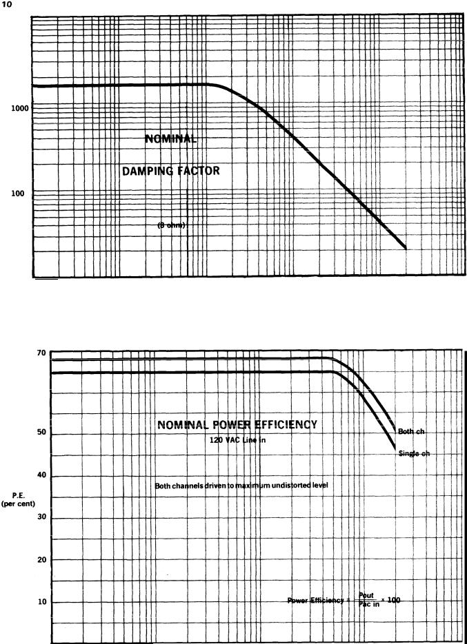
Damping Factor . . . . . . . . . . . . . . . . . . . . . . . . . . . . . . . . . . . . . . . . . . . . . . . . . . . . . . . . . . . . . . . . . . . . . . . . . . . . . . . . . . . . . . . . . . . . . . |
. . . . . . . . . . . . . . |
. . . . . .10 |
Power Efficiency . . . . . . . . . . . . . . . . . . . . . . . . . . . . . . . . . . . . . . . . . . . . . . . . . . . . . . . . . . . . . . . . . . . . . . . . . . . . . . . . . . . . . . . . . . . . |
. . . . . . . . . . . . . . |
. . . . . .10 |
Input Impedance vs. Gain . . . . . . . . . . . . . . . . . . . . . . . . . . . . . . . . . . . . . . . . . . . . . . . . . . . . . . . . . . . . . . . . . . . . . . . . . . . . . |
. . . . . . . . . . . . . . |
. . . . . .11 |


Section 1
DESCRIPTION
1 .1 GENERAL
DC-300A PICTORIAL
The DC-300A is a dual-channel high-power amplifier for precision amplification of frequencies from DC to 20KHz. The unit features extremely low harmonic and intermodulation distortion, very low noise, highest “damping factor,” and quality parts and workmanship. Because of the large output power, It is possible to obtain a monaural 70-volt balanced line without using an output transformer.
The DC-300A contains a new CROWN developed Signal Programmed Automatic Current Executor (SPACE control) electronic amplifier protection circuit which manifests no flyback pulses, thumps, or shut-down. At audio frequencies any impedance load including totally reactive loads may be driven with no adverse effects. Only maximum output power will be affected by variations in load impedance. At sub-sonic to DC frequencies the limiter acts as a VI limiter to provide optimum protection for the extremely rugged silicon hometaxial output devices (total of 16 for a total of 2400W dissipation).
A pair of thermal switches remove power from the unit if overheating occurs due to insufficient ventilation, The AC line is fused to protect the power supply.
See Section 3.2 for a description of the protective systems.
The power supply features a 1 KW transformer and large computer-grade filter capacitors giving over 48 joules of energy storage.
A total of 44 discrete transistors, 1 linear IC (dual op amp),
26 diodes, 1 bridge rectifier, and 3 zener diodes are used in the DC-3OOA circuitry. With the integrated circuit, the effective number of semiconductors is 60 transistors, 30 diodes, and 3 zener diodes.
The output devices, 8/channel, are conservatively employed, having a total peak current rating/channel of 120 amps in a circuit that is limited to a maximum of 28 amps. Among its unique features, the circuitry includes the CROWN-pioneered and patented AB+B output configuration.
The input operational amplifiers are powered by two voltage-regulated supplies. This results in complete channel-to-channel isolation and independence from line voltage variations.
Total direct coupling results in perfect, instantaneous, thump-free overload recovery even on non-symmetrical waveforms. This cannot be said for any AC-coupled amplifier presently in existence. Turn-on is instantaneous with no program delays.
Front-panel controls include two independent heavy-duty level controls and a power switch with an associated pilot light. DC balance controls, which never need adjustment in normal operation, are located behind the front-panel.
1.2 SPECIFICATIONS
1.2.1 STEREO SPECIFICATIONS
Output Power 155 watts per channel minimum RMS (both channels operating) into an 8 ohm load over a bandwidth of 1 Hz-20KHz at a rated RMS sum total harmonic distortion of 0.05% of the fundamental output voltage.
Frequency Response |
±0.1dB DC-20KHz |
at 1 watt into 8 ohms; ±ldB DC-100KHz. |
|||||
1 KHz Power |
180 watts RMS into 8 ohms, per channel, both channels operating, 0.1% total harmonic distortion. |
||||||
Harmonic |
Distortion |
Less than 0.001% from 20Hz-400Hz. and increasing linearly to 0.05% at 20KHzat 155watts RMS |
|||||
|
|
|
|
per channel into 8 ohms. |
|
||
I.M. |
Distortion |
Less |
than 0.05% from 0.01 watts to 0.25 watts and less than 0.01% from 0.25 watts to 155watts |
||||
(60Hz-7KHz 4:1) |
into |
8 ohms, per |
channel. |
|
|||
Slewing |
Rate |
8 volts per microsecond (slewing rate |
is the maximum value of the first derivative of the output |
||||
|
|
|
|
signal, or the maximum slope of the output signal). |
|||
Damping |
Factor |
Greater than 750, |
DC-400Hz into 8 |
ohms. |
|||
Output |
Impedance |
Less than 7 milliohms in series with |
less than 3 microhenries. |
||||
Load |
Impedance |
Rated for 8 ohm usage; safely drives any load Including completely reactive loads. |
|||||
Voltage |
Gain |
20.6±2% or 26.3±0.2dB at maximum |
gain. |
||||
Input |
Sensitivity |
1.75 volts±2% for 155 watts into 8 ohms. |
|||||
Output |
Signal |
Unbalanced, dual |
channel. |
|
|||
1 . 2 . 2 MONAURAL SPECIFICATIONS
Output Power |
310 watts minimum RMS into a 16 ohm load over a |
|
bandwidth of 1 Hz-20KHz at a rated RMS sum total har- |
|
monic distortion of 0.05% of the fundamental output |
|
voltage. |
Frequency Response |
±0.15dB, DC-20KHz at 1 watt into 16 ohms; ±1 dB, DC-6OKHz at 1 watt into 16 ohms. |
1 KHz Power |
360 watts RMS into 16 ohms. |
Harmonic Distortion |
Less than 0.001% from 20Hz-400Hz and increasing linearly to 0.05% at 20KHz at 310 watts into |
|
16 ohms. |
I.M. Distortion |
Less than 0.05% from 0.01 watts to 0.25 watts and less than 0.01% from 0.25 watts to 310 watts |
|
into 16 ohms. |
S l e w i n g R a t e |
16 volts per microsecond. |
Damping Factor |
Greater than 700, DC-400Hz into 16 ohms. |
Output impedance |
Less than 15 milliohms in series with less than 6 microhenries. |
Load Impedance |
Rated for 16 ohm usage; safely, drives any load including completely reactive loads. |
Voltage Gain |
41.2±2% or 32.3±0.2dB at maximum gain. |
Input Sensitivity |
1.75 volts for 310 watts into 16 ohms. |
Output Signal |
Balanced, single channel. |
4
1.2.3 GENERAL SPECIFICATIONS
Hum and Noise
(20Hz-20KHz)
Phase Response
Input Impedance
Amplifier Output
Protection
Overall Protection
Turn-on
Circuit
Power Supply
Power Requirements
Heat Sinking
Chassis
Controls
Connectors
Dimensions
Weight
Finish
110dB below rated output
+0, - 1 5 ° Zero to 20KHz at 1 watt
100K ohms at minimum gain, 10K ohms at maximum gain.
Short, mismatch, and open circuit proof. Limiting is instantaneouswith noflyback pulses, thumps, cutout, etc. No premature limiting on transients.
AC line fused. Thermal switch in AC line protects against overheating caused by insufficient ventilation. Controlled slewing rate voltage amplifiers protect overall amplifier against RF burnouts. Input overload protection is furnished by internal resistance at inputs of amp.
instantaneous, with minimum thumps and no program delay.
Wideband multiple feedback loop design utilizing one linear IC (dual op-amp). Total equivalent of 60 transistors, 30 signal diodes, 3 zeners and 6 rectifier diodes.
1 kilowatt transformer with massive computer-grade filter capacitors storing over 48 joules of energy. Two regulated supplies for complete isolation and stability.
Requires 50-4OOHz AC with selectable taps for 100, 120, 200, 220 and 240V ±10% operation. Draws 40 watts or less on idle, 500 watts at 300 watts total output.
Massive black-anodized heat sinks are thermally joined with the chassis, thereby utilizing the entire amplifier as a heat sink.
All aluminum construction for maximum heat conduction and minimum weight. Heavy aluminum front panel is a single extrusion.
Independent input level controls are on front panel. Power switch, with integral pilot light is on front panel. Non-interacting DC balance controls are mounted behind front panel. A mono-stereo switch is located above the input jacks on the rear panel.
Input - ¼ inch phone jack
Output - Color coded binding posts
AC Line - Three-wire (grounded) male connector on 5 ft. min. cable
19 inch standard rack mount (W.E. hole spacing), 7 inches high, 9 ¾ inches deep (from mounting surface).
45 pounds
Satinized aluminum front panel, with gray suede Lexan insert.

10
TO DC |
10 |
100 |
1K |
10K |
1OOK |
FREQUENCY (Hz)
6 0
10 |
100 |
1KHz |
1OKHz |
1OOKHz |
FREQUENCY (Hz)
 Loading...