


Operation Manual
IM |
INARY |
|
|
PREL |
|
I-Tech Series
I-T4000
I-T6000
I-T8000
Obtaining Other Language Versions: To obtain information in another language about the use of this product, please contact your local Crown Distributor. If you need assistance locating your local distributor, please contact Crown at 574-294-8000.
This manual does not include all of the details of design, production, or variations of the equipment. Nor does it cover every possible situation which may arise during installation, operation or maintenance.
The information provided in this manual was deemed accurate as of the publication date. However, updates to this information may have occurred. To obtain the latest version of this manual, please visit the Crown website at www.crownaudio.com.
Trademark Notice: Crown, Crown Audio, IQ, IQ System, BCA, and Amcron are registered trademarks of Crown International. IQwic, and TCP/IQ are trademarks of Crown International. Other trademarks are the property of their respective owners.
Some models may be exported under the name Amcron.® |
|
©2004 by Crown Audio® Inc., P.O. Box 1000, Elkhart, Indiana 46515-1000 U.S.A. Telephone: 574-294-8000 |
137289-2C |
|
5/04 |
I-Tech Series Power Amplifiers
Important Safety Instructions
1)Read these instructions.
2)Keep these instructions.
3)Heed all warnings.
4)Follow all instructions.
5)Do not use this apparatus near water. Do not expose to dripping or splashing. Do not place objects filled with liquid on unit.
6)Clean only with a dry cloth.
7)Do not block any ventilation openings. Install in accordance with the manufacturer’s instructions.
8)Do not install near any heat sources such as radiators, heat registers, stoves, or other apparatus that produce heat.
9)Do not defeat the safety purpose of the polarized or grounding-type plug. A polarized plug has two blades with one wider than the other. A grounding-type plug has two blades and a third grounding prong. The wide blade or the third prong is provided for your safety. If the provided plug does not fit into your outlet, consult an electrician for replacement of the obsolete outlet.
10)Protect the power cord from being walked on or pinched, particularly at plugs, convenience receptacles, and the point where they exit from the apparatus.
11)Only use attachments/accessories specified
by the manufacturer.
12) Use only with a cart, stand, bracket, or table specified by the manufacturer, or sold with the apparatus. When a cart is used, use caution when moving the cart/apparatus combination to avoid injury from tip-over.
13)Unplug this apparatus during lightning storms or when unused for long periods of time.
14)Refer all servicing to qualified service personnel. Servicing is required when the apparatus has been damaged in any way, such as powersupply cord or plug is damaged, liquid has been spilled or objects have fallen into the apparatus, the apparatus has been exposed to rain or moisture, does not operate normally, or has been dropped.
15)To reduce the risk of fire or electric shock, do
not expose this apparatus to rain or moisture.
TO PREVENT ELECTRIC SHOCK DO NOT REMOVE TOP OR BOTTOM COVERS. NO USER SERVICEABLE PARTS INSIDE. REFER SERVICING TO QUALIFIED SERVICE PERSONNEL.
À PRÉVENIR LE CHOC ÉLECTRIQUE N’ENLEVEZ PAS LES COUVERCLES. IL N’Y A PAS DES PARTIES SERVICEABLE À L’INTÉRIEUR. TOUS REPARATIONS DOIT ETRE FAIRE PAR PERSONNEL QUALIFIÉ SEULMENT.
IMPORTANT
I-Tech Series amplifiers require Class 1 output wiring.
CAUTION
I-Tech amplifiers and their associated sound system may be capable of producing SPL’s that cause hearing loss. The user is encouraged to keep SPL's within safe limits as specified by ANSI, NIOSH or EPA.
MAGNETIC FIELD
CAUTION! Do not locate sensitive high-gain equipment such as preamplifiers or tape decks directly above or below the unit. Because this amplifier has a high power density, it has a strong magnetic field which can induce hum into unshielded devices that are located nearby. The field is strongest on the right side and right bottom of the amplifier (facing the amplifier).
If an equipment rack is used, we recommend locating sensitive equipment at least 20 cm away from the amplifier.
WATCH FOR THESE SYMBOLS:
The lightning bolt triangle is used to alert the user to the risk of electric shock.
The exclamation point triangle is used to alert the user to important operating or maintenance instructions.
FCC COMPLIANCE NOTICE
This device complies with part 15 of the FCC rules. Operation is subject to the following two conditions: (1) This device may not cause harmful interference, and (2) this device must accept any interference received, including interference that may cause undesired operation.
CAUTION: Changes or modifications not expressly approved by the party responsible for compliance could void the user’s authority to operate the equipment.
NOTE: This equipment has been tested and found to comply with the limits for a Class B digital device, pursuant to part 15 of the FCC Rules. These limits are designed to provide reasonable protection against harmful interference in a residential installation. This equipment generates, uses, and can radiate radio frequency energy and, if not installed and used in accordance with the instruction manual, may cause harmful interference to radio communications. However, there is no guarantee that interference will not occur in a particular installation. If this equipment does cause harmful interference to radio or television reception, which can be determined by turning the equipment off and on, the user is encouraged to try to correct the interference by one or more of the following measures:
•Reorient or relocate the receiving antenna.
•Increase the separation between the equipment and receiver.
•Connect the equipment into an outlet on a circuit different from that to which the receiver is connected.
•Consult the dealer or an experienced radio/TV technician for help.
page 2 |
Operation Manual |

I-Tech Series Power Amplifiers
THIS PAGE INTENTIONALLY LEFT BLANK
Operation Manual |
page 3 |
I-Tech Series Power Amplifiers
Getting Started With I-Tech
Welcome! Operating your I-Tech amplifier can be as simple or advanced as you wish. Right out of the box, it works like any other amplifier with stereo loudspeaker loads.
•For bridge-mono operation, see page 5.
•If you want to control and monitor the amplifier with Crown’s IQ System® software, see Section 4.5.4.
•If you want to load DSP presets or perform diagnostics using the amplifier’s LCD control screen (Figure A.3), see Section 4.2.
You can refer to this Quick-Start Guide to get up and running quickly. To learn about I-Tech’s many advanced features, please see the rest of this manual.
Quick-Start Guide: Stereo Wiring
Let’s assume that you unpacked and installed your amplifier with the proper cooling. If not, see Section 2 in this manual. We’ll also assume that you will operate the amplifier in stereo. If you want to operate your amplifier in bridge-mono, skip to page 5.
1. IMPORTANT: Turn off the amplifier. Unplug its power cord from the AC outlet.
The amplifier must be grounded when plugged into AC power.
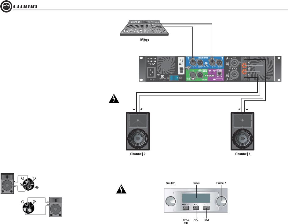
2. See Figure A.1. Connect two cables from your mixer output to the amplifier’s XLR input con-
nectors.
3. Using Class 1 wiring, connect speaker cables either to the amplifier’s Speakon® connectors (as in Figure A.2) or to the 5-way binding posts (as in Figure A.1.)
4. Turn down your mixer master faders. Plug the power cord into the amplifier and then into an AC outlet. Turn on the front-panel power switch. The LCD Control Screen will light up (Figure A.3). Turn down (CCW) both Encoder knobs (Level controls) to maximum attenuation.
5. Play a program through your mixer. Set its level to peak at 0 dB or 0 VU maximum on the mixer meters. Gradually turn up (CW) the amplifier Encoder knobs (Level controls) to the desired volume (Figure A.3).
Top Speakon (Channel 1)
Channel 1
Loudspeaker
Bottom 

 Speakon
 (Channel 2)
Channel 2
Loudspeaker
CAUTION – SHOCK HAZARD: Potentially lethal voltages exist at the output connectors when the amplifier is turned on and is passing a signal.
Figure A.2
Wiring Two Speakers to Two Speakon Connectors for Stereo Operation
Channel 2
Channel 1
Figure A.1 Rear-panel Connections for Stereo Wiring
Figure A.3
The LCD Control Screen
page 4 |
Operation Manual |
I-Tech Series Power Amplifiers
Quick-Start Guide: Bridge-Mono Wiring
Let’s assume that you unpacked and installed your amplifier with the proper cooling. If not, see Section 2 in this manual. We’ll also assume that you will operate the amplifier in Bridge-Mono. Basically you will turn on the amp, enable Bridge-Mono mode with the LCD Control Screen, turn off the amp, wire it, and turn it back on.
1. Be sure that no cables are connected to the amplifier. Plug the amplifier power cord into the amplifier, then into an AC outlet.
2. Turn on the amplifier power switch on the front panel. The LCD Control Screen will light up (Figure A.4).
3. Under the LCD Control Screen, press the Menu/Exit button. Press the Next button until you see Output Mode on the screen.
4. Turn either Encoder knob to select BRIDGE MONO. Press the knob to confirm your choice. Press the Menu/Exit button. Turn down (CCW) both Level controls (Encoders) until you reach maximum attenuation.
5. IMPORTANT: Turn off the amplifier. Unplug its power cord from the AC outlet. The amplifier must be grounded when plugged into AC power.
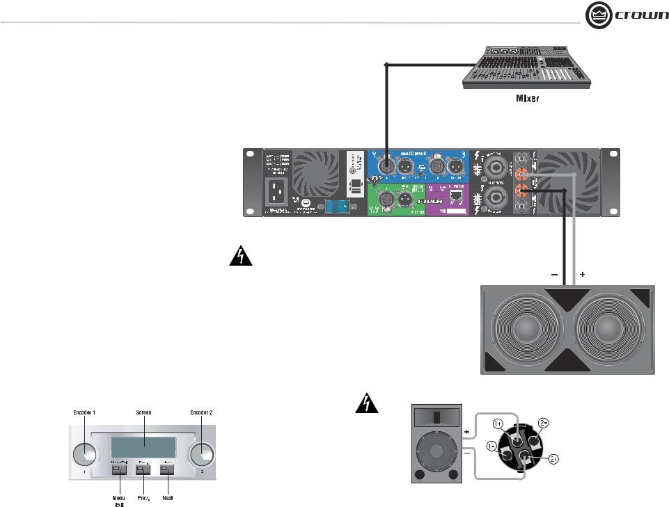
6. See Figure A.5. Connect a cable from your mixer output to the amplifier’s Channel-1 XLR input connector.
7. Using Class 1 wiring, connect the speaker cable either to the amplifier’s top Speakon connector (terminals 1+ and 2+, Figure A.6) or across the red binding posts of both channels (Figure A.5). Do not use the black binding posts in bridge-mono mode.
8. Plug the amplifier’s power cord into the amplifier, then into an AC outlet. Turn on the front-panel power switch.
9. Play a program through your mixer. Set its level to peak at 0 dB or 0 VU maximum on the mixer meters. Gradually turn up (CW) the amplifier’s Encoder-1 knob (Level control) until you reach the desired volume (Figure A.4). Encoder-2 has no effect in Bridge-Mono mode.
Figure A.5 Rear Panel Connections
for Bridge-Mono Wiring
CAUTION – SHOCK HAZARD: Potentially lethal voltages exist at the output connectors when the amplifier is turned on and is passing a signal.
Figure A.4
The LCD Control Screen
Figure A.6
Wiring a Speaker to the Top Speakon Connector for Bridge-Mono Operation
Operation Manual |
page 5 |

I-Tech Series Power Amplifiers
Table of Contents
Important Safety Instructions ............................................................ |
2 |
|
Getting Started with I-Tech ................................................................ |
4 |
|
Quick Start Guide: Stereo Wiring ....................................................... |
4 |
|
Quick Start Guide: Bridge-Mono Wiring ............................................ |
5 |
|
Table of Contents............................................................................... |
6 |
|
1 Welcome ........................................................ |
7 |
|
1.1 |
Features ................................................................................ |
7 |
1.2 |
How to Use This Manual ....................................................... |
7 |
2 Setup ............................................................ |
8 |
|
2.1 |
Unpack and Install Your Amplifier ........................................ |
8 |
2.2 |
Connecting to AC Mains ...................................................... |
9 |
2.3 |
Wire Inputs and Outputs ....................................................... |
9 |
3 Operation ....................................................... |
13 |
|
3.1 |
Protecting Your Speakers ...................................................... |
13 |
3.2 |
Startup Procedure ................................................................. |
13 |
3.3 |
Precautions .......................................................................... |
13 |
3.4 |
Front Panel Controls and Indicators ..................................... |
14 |
3.5 |
Back Panel Controls, Indicators and Connectors .................. |
15 |
4 Advanced Operation............................................ |
16 |
|
4.1 |
Advanced Operation Table of Contents .................................. |
16 |
4.2 |
Navigating the LCD Control Screen ....................................... |
17 |
4.3 |
Presets .................................................................................. |
20 |
4.4 |
Digital-Audio Options (AES/EBU - CobraNet) ....................... |
20 |
4.5 |
TCP-IQ Networking ............................................................... |
21 |
4.6 |
IQ-Controllable Onboard DSP .............................................. |
27 |
4.7 |
CobraNet Functions............................................................... |
29 |
5 Troubleshooting ................................................ |
31 |
|
6 Specifications .................................................. |
33 |
|
6.1 Performance ........................................................................... |
33 |
|
6.2 Charts..................................................................................... |
35 |
|
7 AC Power Draw and Thermal Dissipation .................. |
36 |
|
8 Advanced Features ............................................ |
39 |
|
8.1 |
Protection Systems ............................................................... |
39 |
8.2 |
Global, Switching Power Supply with PFC ........................... |
39 |
8.3 |
3rd Generation Class I Circuitry ............................................ |
39 |
8.4. Color-Coded Rear Overlay ................................................... |
39 |
|
8.5 |
Rear Rack Ears with Integral EZ-Rack Pin .............................. |
39 |
9 Appendix: TCP/IQ Network Basics ........................... |
40 |
|
10 Service ......................................................... |
44 |
|
11 Warranty ....................................................... |
45 |
|
Crown Factory Service Information Form ......................................... |
47 |
|
page 6 |
Operation Manual |
I-Tech Series Power Amplifiers
I-T4000 |
20 Hz - 20 kHz |
Power |
|
2-ohm Dual (per ch.) |
1,800W |
4-ohm Dual (per ch.) |
2,000W |
8-ohm Dual (per ch.) |
1,250W |
4-ohm Bridge |
3,600W |
8-ohm Bridge |
4,000W |
20 Hz - 20 kHz Power refers to guaranteed minimum power in watts with 0.35% THD.
I-T6000 |
20 Hz - 20 kHz |
Power |
|
2-ohm Dual (per ch.) |
2,500W |
4-ohm Dual (per ch.) |
3,000W |
8-ohm Dual (per ch.) |
1,500W |
4-ohm Bridge |
5,000W |
8-ohm Bridge |
6,000W |
20 Hz - 20 kHz Power refers to guaranteed minimum power in watts with 0.35% THD.
I-T8000 |
20 Hz - 20 kHz |
Power |
|
2-ohm Dual (per ch.) |
3,500W |
4-ohm Dual (per ch.) |
4,000W |
8-ohm Dual (per ch.) |
2,100W |
4-ohm Bridge |
7,000W |
8-ohm Bridge |
8,000W |
20 Hz - 20 kHz Power refers to guaranteed minimum power in watts with 0.35% THD.
Menu/Exit |
Prev |
Next |
1 |
|
2 |
|
|
|
1 Welcome
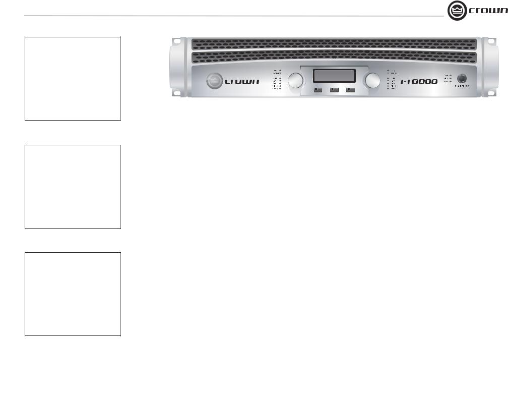
The Crown® I-Tech Series offers amazing power, light weight and ease of use for touring sound applications. Unlike other amplifiers, it includes onboard DSP, an LCD control screen, and a built-in network connection.
Modern power amplifiers are sophisticated pieces of engineering capable of producing extremely high power levels. They must be treated with respect and correctly installed if they are to provide the many years of reliable service for which they were designed.
In addition, I-Tech Series amplifiers include a number of features which require some explanation before they can be used to their maximum advantage.
Please take the time to study this manual so that you can obtain the best possible service from your amplifier.
1.1 Features
•Global Power Supply with PFC (Power Factor Correction) works anywhere in the world.
•High power density, up to 8000 watts in a 2U chassis.
•Highest output voltage in the industry (200V peak) provides clean transient peaks.
•3rd-generation patented Class I (BCA®) circuitry couples power efficiently to the load and provides low AC current drain.
•Onboard DSP with 24-bit, 96 kHz Cirrus Logic A/D and D/A converters.
•Pushbutton presets simplify setup. Custom presets for various loudspeakers can be downloaded.
•AES/EBU digital audio input. Ethernet connector accepts RJ-45 connector for TCP/IQ networking. Analog and digital thru connectors. CobraNet™ input available in optional CN models, coming soon.
•LCD Control Screen is used to adjust the amplifier's attenuation and muting, configure the amp, set up and view error monitoring, and recall DSP presets to reconfigure the amp for various applications.
•Comprehensive array of indicators provide accurate diagnostics: Power, Data, Bridge, along with Ready, Signal, Clip, Thermal and Fault for each channel.
•AC mains indicator in power switch glows green when AC power is present.
•Light weight due to aluminum chassis, special internal construction and switching power supply.
•Thermal management controller and two discrete thermal zones with variable-speed fans, forced-air cooling.
•The rear rack ears have a built-in EZ-Rack Pin for easier installation.
•Advanced protection circuitry guards against: shorted outputs, DC, mismatched loads, general overheating, under/over voltage, high-frequency overloads and internal faults.
•Three-Year, No-Fault, Fully Transferable Warranty completely protects your investment and guarantees its specifications.
1.2 How to Use This Manual
This manual provides you with the necessary information to safely and correctly setup and operate your amplifier. It does not cover every aspect of installation, setup or operation that might occur under every condition. For additional information, please consult Crown’s
Amplifier Application Guide (available online at www.crownaudio.com), Crown Technical Support, your system installer or retailer.
We strongly recommend you read all instructions, warnings and cautions contained in this manual. Also, for your protection, please send in your warranty registration card today. And save your bill of sale — it’s your official proof of purchase.
Operation Manual |
page 7 |
I-Tech Series Power Amplifiers
2 Setup
2.1 Unpack and Install Your Amplifier
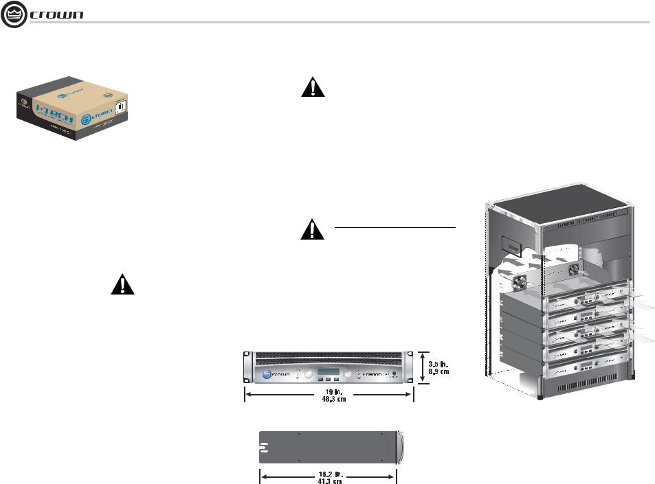
Please unpack and inspect your amplifier for any damage that may have occurred during transit. If damage is found, notify the transportation company immediately. Only you can initiate a claim for shipping damage. Crown will be happy to help as needed. Save the shipping carton as evidence of damage for the shipper’s inspection.
We also recommend that you save all packing materials so you will have them if you ever need to transport the unit. Never ship the unit without the factory pack.
YOU WILL NEED (not supplied):
• Input wiring cables
• Output wiring cables
Rack for mounting amplifier (or a stable surface for stacking)
WARNING: Before you start to set up your amplifier, make sure you read and observe the Important Safety Instructions found at the beginning of this manual.
CAUTION: Before you begin, make sure your amplifier is disconnected from the power source, with the power switch in the “off” position and all level controls turned completely down (counterclockwise).
Use a standard 19-inch (48.3 cm) equipment rack (EIA RS-310B). See Figure 2.1 for amplifier dimensions.
You may also stack amps without using a cabinet.
NOTE: When transporting, amplifiers should be supported at both front and back.
MAGNETIC FIELD
CAUTION! Do not locate sensitive high-gain equipment such as preamplifiers or tape decks directly above or below the unit. Because this amplifier has a high power density, it has a strong magnetic field which can induce hum into unshielded devices that are located nearby. The field is strongest on the right side and right bottom of the amplifier (facing the amplifier).
If an equipment rack is used, we recommend locating sensitive equipment at least 20 cm away from the amplifier.
When using an equipment rack, mount units directly on top of each other. Close any open spaces in rack with blank panels. DO NOT block front, rear or side air vents. The side walls of the rack should be a minimum of two inches (5.1 cm) away from the amplifier sides, and the back of the rack should be a minimum of four inches (10.2 cm) from the amplifier back panel.
Figure 2.2 illustrates standard amplifier airflow.
Figure 2.2 Airflow
Figure 2.1
Dimensions
page 8 |
Operation Manual |

I-Tech Series Power Amplifiers
2 Setup
2.2 Connecting to AC Mains
WARNING: The third (ground) prong of the supplied AC power cord connector is a required safety feature. Do not attempt to disable this ground connection by using an adapter or other methods.
Amplifiers don’t create energy. The AC mains voltage and current must be sufficient to deliver the power you expect. You must operate your amplifier from an AC mains power source with not more than a 10% variation above or a 15% variation below the amplifier’s specified line voltage range and within the specified frequency requirements (indicated on the amplifier’s back panel label). If you are unsure of the output voltage of your AC mains, please consult your electrician.
2.3 Wire Inputs and Outputs
2.3.1 Wiring basics
•Always use shielded wire for input wiring. The higher the density of the shield (the outer conductor) the better. Spiral wrapped shield is not recommended.
•When using unbalanced lines keep the cables as short as possible. Avoid lengths greater than 10 feet (3 meters).
•Do not run the audio input cables together with the high-level wiring such as loudspeaker wires or AC cords. (This lessens the chance of hum and noise being induced into the input cables.)
•Turn the entire sound system off before changing any connections. Crown is not liable for damage incurred when any transducer or component is overdriven.
DO NOT USE THE CHANNEL 2 INPUT if the amplifier is used in BridgeMono mode.
For additional information on audio input wiring please refer to the Crown Amplifier Application Guide available online at www.crownaudio.com. It contains helpful information on preventing unwanted subsonic frequencies, radio frequency interference, ground loops, and feedback oscillation.
Operation Manual |
page 9 |
I-Tech Series Power Amplifiers
2Setup
2.3.2Choose Input Wire and Connectors
Crown recommends using pre-built or professionally wired, balanced line (two-conductor plus shield), 22-24 gauge cables and connectors. Use 3-pin male XLR connectors.
Unbalanced line may also be used but may result in noise over long cable runs.
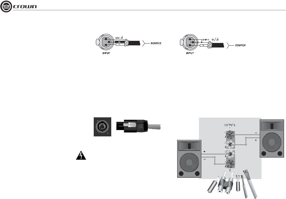
Figure 2.1 shows connector pin assignments for balanced analog wiring or AES/EBU digital wiring. Figure 2.2 shows connector pin assignments for unbalanced analog wiring.
I-Tech models with a CN suffix accept CobraNet network signals. With CobraNet, you can send digital audio and amplifier IQ®-control signals on the same Category 5 cable. This single cable plugs in to the Network connector on the rear panel.
NOTE: Custom wiring should only be performed by qualified personnel.
2.3.3 Choose Output Wire and Connectors
Crown recommends using pre-built or professionally wired, highquality, twoor four-conductor, heavy gauge speaker wire and connectors. Use Class 1 output wiring. You may use a 4-pole Speakon connector (Figure 2.3) or banana plugs, spade lugs, or bare wire for your output connectors (Figure 2.4). To prevent the possibility of short-circuits, wrap or otherwise insulate exposed loudspeaker cable connectors.
CAUTION – SHOCK HAZARD: Potentially lethal voltages exist at the output connectors when the amplifier is turned on and is passing a signal.
Using the guidelines below, select the appropriate size of wire based on the distance from amplifier to speaker.
Distance |
Wire Size |
|
up to 25 ft. |
16 AWG |
|
26-40 ft. |
14 |
AWG |
41-60 ft. |
12 |
AWG |
61-100 ft. |
10 |
AWG |
101-150 ft. |
8 |
AWG |
151-250 ft. |
6 |
AWG |
CAUTION: Never use shielded cable for output wiring.
Figure 2.1
Balanced Analog Input Connector Wiring or AES/EBU Digital Connector Wiring
Figure 2.3
Left: Speakon Output Connector on Back Panel Right: Speakon Cable Connector
Figure 2.2 Unbalanced Analog Input Connector Wiring
Figure 2.4
5-Way Binding Post Connections
page 10 |
Operation Manual |
I-Tech Series Power Amplifiers
2 Setup
2.3.4 Stereo Mode Wiring
Typical input and output wiring is shown in Figure 2.5.
IMPORTANT: Turn off the amplifier and unplug its power cord.
INPUTS: Choose one of these options:
•Connect analog input wiring for both channels.
•Connect an AES/EBU digital signal to the AES/EBU connector.
•Connect a CobraNet network cable with a digital signal to the Network connector (CN models only).
OUTPUTS: Maintain proper polarity (+/–) on output connectors. Use Class 1 output wiring.
Figure 2.5 shows how to wire stereo speakers to the 5-way binding posts. Connect Channel 1 loudspeaker’s positive (+) lead to Channel 1 positive (red) terminal of amp; repeat for negative (–). Repeat Channel 2 wiring as for Channel 1.
To wire stereo speakers to the Speakon connectors, use one of these methods:
Method 1 (Table 1 and Figure 2.6): Wire one Speakon cable connector to two speakers. Insert the Speakon cable connector into the amplifier’s top Speakon connector.
Method 2 (Table 2 and Figure 2.7): Plug the Channel 1 speaker into the Channel 1 (top) Speakon connector, and plug the Channel 2 speaker into the Channel 2 (bottom) Speakon connector.
Table 1
Stereo Wiring Method 1: Use Top Speakon Only
|
|
|
PIN |
1+ |
1– |
2+ |
2– |
|
|
|
||||
|
|
|
|
|
|
|
|
|
|
|
|
|
|
|
|
|
|
CH |
1+ |
1– |
2+ |
2– |
|
|
|
||||
|
|
|
|
|
|
|
|
|
|
|
|
|
|
|
|
|
|
|
|
|
|
|
|
|
|
|
|
|
|
|
|
|
|
|
|
|
|
|
|
|
|
|
|
|
|
|
|
|
|
|
|
|
|
|
|
|
|
|
|
|
|
|
|
|
|
|
|
|
|
|
|
|
|
|
|
|
|
|
|
|
|
|
|
|
|
|
|
|
|
|
|
|
|
|
|
|
|
|
|
|
|
|
|
|
Figure 2.6 Wiring Two Stereo Speakers to the Top Speakon Connector
Channel 2
Channel 1
Figure 2.5
System Wiring,
Stereo Mode
|
Table 2 |
|
Top Speakon |
|
|
|
(Channel 1) |
Figure 2.7 |
|
Stereo Wiring Method 2: Use Both Speakons |
|
Stereo Wiring Using |
||
|
Both Speakon |
|||
|
|
|
|
|
PIN |
1+ |
1– |
|
Connectors |
Channel 1 |
|
|||
Top Speakon |
|
|
|
|
|
|
Loudspeaker |
|
|
CH |
1+ |
1– |
|
|
|
|
|||
PIN |
1+ |
1– |
Bottom |
|
Speakon |
|
|||
Bottom Speakon |
|
|
(Channel 2) |
|
CH |
2+ |
2– |
|
Channel 2 |
|
|
|
|
|
|
|
|
|
Loudspeaker |
Operation Manual |
page 11 |

I-Tech Series Power Amplifiers
2 Setup
2.3.5 Bridge-Mono Mode
Overview: Turn on the amp, enable Bridge-Mono mode using the LCD Control Screen, turn off the amp, wire it, and turn it back on.
1.Be sure that no cables are connected to the amplifier. Turn on the front-panel power switch. The LCD Control Screen will light up (Figure 2.8).
2.Under the LCD Control Screen, press the Menu/Exit button. Press the Next button until you see OUTPUT MODE on the screen.
3.Turn an Encoder knob to select BRIDGE MONO. Press the knob to confirm your choice. Press Menu/Exit. Turn down both level controls (Encoders) until you reach maximum attenuation.
4. IMPORTANT: Turn off the amplifier and unplug its power cord.
INPUTS: There are three ways to connect an input signal to the amplifier (Figure 2.9):
•Connect an analog signal source to the Channel-1 amplifier input.
•Connect an AES/EBU digital signal source to the Digital Input IN connector.
•Connect a CobraNet network signal with digital audio to the Network connector (CN models only).
NOTE: Crown provides a reference of wiring pin assignments for commonly used connector types in the Crown Amplifier Application Guide available at www.crownaudio.com.
OUTPUTS: Use Class 1 output wiring. There are two ways to wire the amplifier output connectors for Bridge-Mono mode:
1)Wire the speaker across the red binding post of each channel (Figure 2.9). Do not use the black binding posts when operating in Bridge-Mono mode.
2)Wire the speaker only to the top Speakon connector as shown in Table 3 and Figure 2.10.
Figure 2.8
The LCD Control Screen
NOTE: In Bridge-Mono mode, the Channel 1 Level control sets the level; the Channel 2 Level control is defeated.
Figure 2.9 Bridge-Mono Wiring to Binding Posts
Table 3
Top Speakon Wiring for Bridge-Mono
PIN |
1+ |
2+ |
|
|
|
SPKR |
+ |
– |
|
|
|
Figure 2.10
Wiring a Speaker in Bridge-Mono Mode to the Top Speakon Connector
page 12 |
Operation Manual |

I-Tech Series Power Amplifiers
3Operation
3.1Protecting Your Speakers
It's wise to avoid clipping the amplifier signal. Not only does clipping sound bad, it can damage high-frequency drivers. To prevent clipping, use IQwic™ software to enable the peak voltage limiter and average power limiter in your amplifier’s built-in DSP. That way, no matter how strong a signal your mixer produces, the amplifier will not clip. Set the limiter threshold so that mixer signals above 0 dB or 0 VU on the mixer meters do not quite drive the amplifier into clipping.
Also, avoid sending strong subsonic signals to the amplifier. Highlevel, low-frequency signals from breath pops or dropped microphones can blow out drivers. To prevent subsonic signals, use one of these methods:
•Insert a highpass filter between mixer output and amplifier input (or between mixer and limiter).
•Use the I-Tech’s onboard DSP to set up a highpass filters. This can be done using the Wizard in the IQwic software.
•Switch in highpass filters at your mixer. Set the filter to as high a frequency as possible that does not affect your program. For example, try 35 Hz for music and 75 Hz for speech. On each mixer input channel, set the filter frequency just below the lowest fundamental frequency of that channel's instrument.
3.2 Startup Procedure
Use the following procedure when first turning on your amplifier:
1.Turn down the level of your audio source.
2.Turn on the Power switch. The Power indicator should glow and the LCD Control Screen should light up.
3.Turn down the amplifier Encoder knobs (Level controls).
4.Turn up the level of your audio source to an optimum level.
5.Turn up the amplifier Encoder knobs (Level controls) until the desired loudness or power level is achieved.
6.Turn down the level of your audio source to its normal range.
If you ever need to make any wiring or installation changes, don’t forget to disconnect the power cord.
For help with determining your system’s optimum gain structure (signal levels) please refer to the Crown Amplifier Application Guide, available online at www.crownaudio.com.
3.3 Precautions
Your amplifier is protected from internal and external faults, but you should still take the following precautions for optimum performance and safety:
1.Before use, your amplifier first must be configured for proper operation, including input and output wiring hookup. Improper wiring can result in serious operating difficulties. For information on wiring and configuration, please consult the Setup section of this manual or, for advanced setup techniques, consult Crown’s
Amplifier Application Guide available online at www.crownaudio.com.
2.Use care when making connections, selecting signal sources and controlling the output level. The load you save may be your own!
3.Do not short the ground lead of an output cable to the input signal ground. This may form a ground loop and cause oscillations.
4.WARNING: Never connect the output to a power supply, battery or power main. Electrical shock may result.
5.Tampering with the circuitry, or making unauthorized circuit changes may be hazardous and invalidates all agency listings.
6.Do not operate the amplifier with the red Clip LEDs constantly flashing.
7.Do not overdrive the mixer, which will cause clipped signal to be sent to the amplifier. Such signals will be reproduced with extreme accuracy, and loudspeaker damage may result.
8.Do not operate the amplifier with less than the rated load impedance. Due to the amplifier’s output protection, such a configuration may result in premature clipping and speaker damage.
9.CAUTION – SHOCK HAZARD: Potentially lethal voltages exist at the output connectors when the amplifier is turned on and is passing a signal.
Remember: Crown is not liable for damage that results from overdriving other system components.
Operation Manual |
page 13 |
I-Tech Series Power Amplifiers
3 Operation
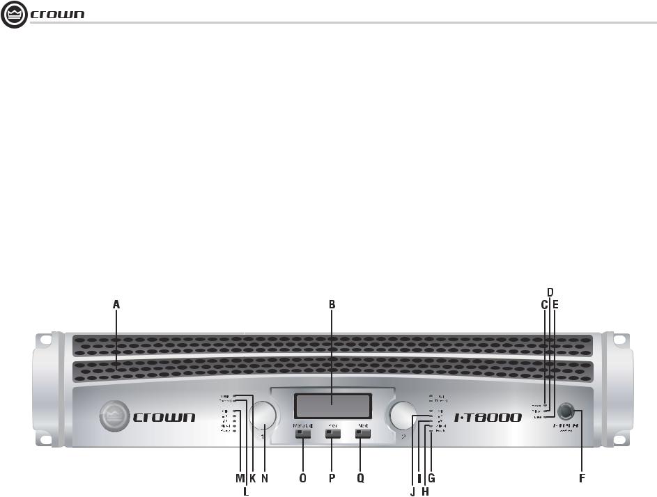
3.4 Front Panel Controls
and Indicators
A. Cooling Vents
Front-to-rear forced airflow through foam dust filter.
LCD Control Screen and Controls
B. LCD Control Screen
Integrated LCD with white backlight, controls amplifier setup and operation.
The LCD Control Screen and its controls let the user adjust the amplifier's attenuation and muting, configure the amp, set up and view error monitoring (such as temperature and load supervision), and recall DSP presets. The presets allow the user to quickly reconfigure the amp for various applications.
C. Level Controls (Encoders)
Speed-sensitive, 0.5 dB steps, range 0 to –90 dB.
These two knobs affect the Channel-1 and Channel-2 output levels. They also select Menu items and adjust parameter values that are displayed on the LCD control screen.
D. Menu/Exit Button
“Menu” enters the main menu. “Exit” leaves the menu.
E. Prev Button
Selects the previous item in the menu.
F. Next Button
Selects the next item in the menu.
Thermal and Fault Indicators
G.Thermal Indicator
Red LED, one per channel, illuminates when the channel has shut down, or is very near shutting down, due to thermal stress or overload.
H.Fault Indicator
Red LED, one per channel, flashes when the amplifier output channel has stopped operating. Usually this means that the amplifier must be serviced.
I.Clip Indicator
Red LED, one per channel, illuminates when the channel’s output signal reaches the onset of audible clipping. The Clip Indicator also will illuminate during Thermal Level Control (TLC) limiting.
Signal Indicators
Three green LEDS per channel indicate the amplifier’s input and output signal levels. From top to bottom the LEDs are:
J. –10 dB: amplifier output is 10 dB below clipping.
K. –20 dB: amplifier output is 20 dB below clipping.
L.Signal: input signal is above –40 dBu.
M.Ready Indicator
Green LED, one per channel, illuminates when the
channel is initialized and ready to produce audio output. Indicator is off when the channel is set to standby mode via the IQ system.
N.Power Indicator
Blue LED indicates amplifier has been turned on and AC power is available. The LED will flash when the AC line voltage is 15% above or below the nominal rated range.
O.Bridge Mode Indicator
Yellow LED illuminates when the amplifier is set to Bridge-Mono mode.
P.Data Indicator
Yellow LED indicates IQ Network data activity. Data indicator flashes only when the amplifier is polled for data, or is polled to see whether it is online.
Q.Power Switch
Push-on/push-off switch glows green when AC power is present at the power cord and the amplifier circuit breaker is in the “on” position.
Figure 3.1 Front Panel Controls and Indicators
page 14 |
Operation Manual |
I-Tech Series Power Amplifiers
3 Operation
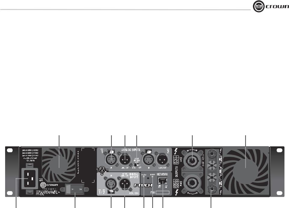
3.5 Back Panel Controls, Indicators and Connectors
A. Fans
Provide front-to-back forced airflow for cooling.
ANALOG INPUTS SECTION
B. Balanced Analog XLR Inputs
A 3-pin female XLR connector for each channel.
C. Balanced Analog XLR Loop-Through Outputs
Two 3-pin male XLR output connectors are provided (one per channel). The signal at these connectors is paralled with the input signal for feeding the input signal to other amplifiers.
D. Input Ground-lift Switch
Isolates input ground from AC ground. Can be used to prevent ground loops.
OUTPUTS SECTION
E. 4-Pole Speakon Output Connectors
Two high-current, 50A Neutrik® Speakon NL4MLP (mates with NL4FC), one per channel. Class 1 output wiring required.
These two connectors accept 2-pole or 4-pole Speakon connectors. See Figures 2.5 through 2.10 and Tables 1, 2 and 3 for connector wiring. The top Speakon connector is wired for both channels so it can be used for bridgemono wiring or for stereo wiring of two speakers to a single Speakon connector.
M. 5-Way Binding Post Output Jacks
One pair per channel of high-current, 60A color-coded 5-way binding posts. Accepts banana plugs, spade lugs or bare wire.
F. Power Cord Connector
Standard 20 amp IEC inlet. Voltage range is indicated above IEC inlet.
G. Reset Switch/Circuit Breaker
If the current draw of the amplifier exceeds safe limits, this breaker automatically disconnects the power supply from the AC mains. The switch resets the circuit breaker.
DIGITAL INPUTS SECTION
H. AES/EBU Digital Input
This 3-pin female XLR connector accepts a digital signal in the AES/EBU format.
I. AES/EBU Digital Loop-through Output
Male XLR active/re-clocked AES/EBU digital loop-through. The signal at this connector duplicates the digital input signal for feeding the input signal to other amplifiers.
NETWORKING SECTION
J. Preset Indicator
Yellow LED flashes to signal the number of the current preset if active.
K. IQ Data Indicator
Yellow LED indicates IQ Network data activity. Data indicator flashes only when the amplifier is polled for data, or is polled to see whether it is online.
L. Network Connector
This Ethernet connector accepts an RJ-45 connector for TCP/IQ networking. Built into the connector is a yellow LINK ACT indicator that shows network activity, and a green 100Mb indicator that shows a 100Mb network connection.
In optional CN models, coming soon, the Ethernet connector accepts a CobraNet network signal, which provides both digital audio and IQ control/monitoring on a single cable.
A B C D E A
F G H I J K L M
Figure 3.2 Back Panel Controls and Connectors
Operation Manual |
page 15 |
 Loading...