


ComTech DriveCore Operation Manual
CT 475
CT 4150
CT 875
CT 8150
Obtaining Other Language Versions: To obtain information in another language about the use of this product, please contact your local Crown Distributor. If you need assistance locating your local distributor, please contact Crown at 574-294-8000.
This manual does not include all of the details of design, production, or variations of the equipment. Nor does it cover every possible situation which may arise during installation, operation or maintenance.
The information provided in this manual was deemed accurate as of the publication date. However, updates to this information may have occurred. To obtain the latest version of this manual, please visit the Crown website at www.crownaudio.com.
Trademark Notice: Com-Tech, BCA, Crown, Crown Audio, Amcron and Multi-Mode are registered trademarks of Crown International. IQwic, PIP and PIP2 are trademarks of Crown International. Other trademarks are the property of their respective owners.
Some models may be exported under the name Amcron.®
© 2011 by Harman International®, Inc. 1718 W. Mishawaka Rd., Elkhart, Indiana 46517-9439 U.S.A. Telephone: 574-294-8000
143368-1 4/11
CT Power Amplifiers
Important Safety Instructions Importantes Instructions de Sécurité
1.Read these instructions.
2.Keep these instructions.
3.Heed all warnings.
4.Follow all instructions.
5.Do not use this apparatus near water.
6.Clean only with a dry cloth.
7.Do not block any ventilation openings. Install in accordance with the manufacturer’s instructions.
8.Do not install near any heat sources such as radiators, heat registers, stoves, or other apparatus (including amplifiers) that produce heat.
9.Do not defeat the safety purpose of the polarized or grounding-type plug. A polarized plug has two blades with one wider than the other. A grounding-type plug has two blades and a third grounding prong. The wide blade or the third prong is provided for your safety. If the provided plug does not fit into your outlet, consult an electrician for replacement of the obsolete outlet.
10.Protect the power cord from being walked on or pinched, particularly at plugs, convenience receptacles, and the point where they exit from the apparatus.
11.Only use attachments/accessories specified by the manufac turer.
12. Use only with a cart, stand, tripod, bracket, or table specified by the manufacturer, or sold with the apparatus. When a cart is used, use caution when moving the cart/ apparatus combination to avoid injury from tip-over.
13.Unplug this apparatus during lightning storms or when unused for long periods of time.
14.Refer all servicing to qualified service personnel. Servicing is required when the apparatus has been damaged in any way, such as power-supply cord or plug is damaged, liquid has been spilled or objects have fallen into the apparatus, the apparatus has been exposed to rain or moisture, does not operate normally, or has been dropped.
15.Use the mains plug to disconnect the apparatus from the mains.
16.WARNING: TO REDUCE THE RISK OF FIRE OR ELECTRIC SHOCK, DO NOT EXPOSE THIS APPARATUS TO RAIN OR MOISTURE.
17.DO NOT EXPOSE THIS EQUIPMENT TO DRIPPING OR
SPASHING AND ENSURE THAT NO OBJECTS FILLED
WITH LIQUIDS, SUCH AS VASES, ARE PLACED ON THE
EQUIPMENT.
18.THE MAINS PLUG OF THE POWER SUPPLY CORD SHALL REMAIN READILY OPERABLE.
Wichtige Sicherheitsinstruktionen
Instrucciones de Seguridad Importantes
TO PREVENT ELECTRIC SHOCK DO NOT REMOVE TOP OR BOTTOM COVERS. NO USER SERVICEABLE PARTS INSIDE. REFER SERVICING TO QUALIFIED SERVICE PERSONNEL.
À PRÉVENIR LE CHOC ÉLECTRIQUE N’ENLEVEZ PAS LES COUVERCLES. IL N’Y A PAS DES PARTIES SERVICEABLE À L’INTÉRIEUR. TOUS REPARATIONS DOIT ETRE FAIRE PAR PERSONNEL QUALIFIÉ SEULMENT.
PARA PREVENIR UN CHOQUE ELÉCTRICO, NO RETIRE LAS CUBIERTAS SUPERIOR O INFERIOR. NO EXISTEN PARTES QUE PUEDAN SER REPARADAS POR EL USUARIO AL INTERIOR. REMITA EL SERVICICO AL PERSONAL TÉCHNICAL CALIFICADO.
TO COMPLETELY DISCONNECT THIS EQUIPMENT FROM THE AC MAINS, DISCONNECT THE POWER SUPPLY CORD PLUG FROM THE AC RECEPTACLE. THE MAINS PLUG OF THE POWER SUPPLY CORD SHALL REMAIN READILY OPERABLE.
IMPORTANT
CT Series amplifiers require Class 2 output wiring.
Les amplificateurs de série de CT exigent des câbles de sortie de classe 2.
CT-Reihe-Verstärker verlangen Klasse die 2 Produktionsverdrahtung. Los amplificadores de la Serie CT requieren de un cableado de salida Clase 2.
MAGNETIC FIELD
CAUTION! Do not locate sensitive high-gain equipment such as preamplifiers directly above or below the unit. Because this amplifier has a high power density, it has a strong magnetic field which can induce hum into unshielded devices that are located nearby. The field is strongest just above and below the unit.
If an equipment rack is used, we recommend locating the amplifier(s) in the bottom of the rack and the preamplifier or other sensitive equipment at the top.
POUR DÉMONTER COMPLÈTEMENT L’ÉQUIPEMENT DE L’ALIMENTATION GÉNÉRALE, DÉMONTER LE CÂBLE D’ALI MENTATION DE SON RÉCEPTACLE. LA PRISE D’ALIMENTATION RESTERA AISÉMENT FONCTIONNELLE.
PARA DESCONECTAR COMPLETAMENTE EL EQUIPO DEL SUMINSTRO ELECTRICO, DESCONECTE EL CABLE DE ALI MENTACION DE LA TOMA DE CA. LAS PATAS DEL CONECTOR DEL CABLE DE ALIMENTACIÓN DEBERAN MANTENERSE EN BUEN ESTADO.
WATCH FOR THESE SYMBOLS:
The lightning bolt triangle is used to alert the user to the risk of electric shock.
The exclamation point triangle is used to alert the user to important operating or maintenance instructions.
REGARDEZ CES SYMBOLES:
La triangle avec le sigle ‘’foudre’’ est employée pour alerter l’utilisateur au risque de décharge électrique. Le triangle avec un point d’exclamation est employée pour alerter l’utilisateur d’instruction importantes pour lors opérations de maintenance.
ATENCION CON ESTOS SÍMBOLOS:
El triángulo con el símbolo de rayo eléctrico es usado para alertar al usuario de el riesgo de un choque eléctrico.
El triángulo con el signo de admiración es usado para alertar al usuario de instrucciones importantes de operación o man tenimiento.
FCC COMPLIANCE NOTICE
This device complies with part 15 of the FCC rules. Operation is subject to the following two conditions: (1) This device may not cause harmful interference, and (2) this device must accept any interference received, including interference that may cause undesired operation.
CAUTION: Changes or modifications not expressly approved by the party responsible for complicance could void the user’s authority to operate the euqipment.
NOTE: This equipment has been tested and found to comply with the limits for a Class B digital device, pursuant to part 15 of the FCC Rules. These limits are designed to provide reasonable protection against harmful interference in a residential installation. This equipment generates, uses, and can radiate radio frequency energy and, if not installed and used in accordance with the instruction manual, may cause harmful interference to radio communications. However, there is no guarantee that interference will not occur in a particular installation. If this equipment does cause harmful interference to radio or television reception, which can be determined by turning the equipment off and on, the user is encouraged to try to correct the interference by one or more of the following measures:
•Reorient or relocate the receiving antenna.
•Increase the separation between the equipment and receiver.
•Connect the equipment into an outlet on a circuit different from that to which the receiver is connected.
•Consult the dealer or an experienced radio/TV technician for help.
page 2 |
Operation Manual |

CT Power Amplifiers
DECLARATION of CONFORMITY
ISSUED BY: Harman International
1718 W. Mishawaka Road
Elkhart, Indiana 46517 U.S.A.
European Representative’s Name and Address:
David Budge
10 Harvest Close
Yateley GU46 6YS
United Kingdom
Equipment Type: Power Amplifiers
Family Name: CT series
Model Names: CT8150, CT875, CT4150, CT475
EMC Standards:
EN 55103-1:1997 Electromagnetic Compatibility – Product Family Standard for Audio, Video, Audio-Visual and Entertainment Lighting Control Apparatus for Professional Use, Part 1: Emissions EN 55103-1:1997 Magnetic Field Emissions-Annex A @ 10 cm and 1 M
EN 61000-3-2:2006 & Amd 1: 2008 & AMd 2 : 2009 Limits for Harmonic Current Emissions (equipment input current ≤16A per phase) EN 61000-3-3:1998 Limitation of Voltage Fluctuations and Flicker in Low-Voltage Supply Systems Rated Current ≤16A
EN 55022:2006 Limits and Methods of Measurement of Radio Disturbance Characteristics of ITE: Radiated, Class B Limits; Conducted, Class B
EN 55103-2:1997 Electromagnetic Compatibility – Product Family Standard for Audio, Video, Audio-Visual and Entertainment Lighting Control Apparatus for Professional Use, Part 2: Immunity EN 61000-4-2:2009 Electrostatic Discharge Immunity (Environment E2-Criteria B, 4k V Contact, 8k V Air Discharge)
EN 61000-4-3:2006 Radiated, Radio-Frequency, Electromagnetic Immunity (Environment E2, Criteria A) EN 61000-4-4:2007 Electrical Fast Transient/Burst Immunity (Criteria B)
EN 61000-4-5:2006 Surge Immunity (Criteria B)
EN 61000-4-6:2009 Immunity to Conducted Disturbances Induced by Radio-Frequency Fields (Criteria A) EN 61000-4-11:2001 Voltage Dips, Short Interruptions and Voltage Variation
Safety Standard:
IEC 60065: 2001: 7Ed & Amd 1: 2005 Safety Requirements - Audio Video and Similar Electronic Apparatus
I certify that the product identified above conforms to the requirements of the EMC Council Directive 2004/108/EC and the Low Voltage Directive 2006/95/EC.
Signed
Scott Potosky
Title: Director of Engineering
Date of Issue: March 16, 2011
Operation Manual |
Due to line current harmonics, we recommend that you contact your supply authority before connection. |
page 3 |

CT Power Amplifiers
Table of Contents
Important Safety Instructions ....................................... |
2 |
Declaration of Conformity ........................................... |
3 |
1 Welcome .......................................... |
5 |
1.1 Features ........................................................... |
5 |
2 How to Use This Manual ........................ |
5 |
3 Features........................................... |
5 |
4 Setup ............................................... |
6 |
4.1 Unpack Your Amplifier ....................................... |
6 |
4.2 Install Your Amplifier ........................................ |
6 |
4.3 Ensure Proper Cooling ..................................... |
6 |
4.4 Choose Input Wire and Connectors ................... |
7 |
4.5 Choose Output Wire and Connectors ................ |
7 |
4.6 Wire Your System .............................................. |
8 |
4.7 Connect to AC Mains ........................................ |
8 |
4.8 Startup Procedure ............................................. |
9 |
5 Precautions ....................................... |
9 |
6 Front Panel ........................................ |
10 |
7 Back Panel......................................... |
11 |
8 Amp Configuration................................ |
12 |
8.1. 70Hz HPF (High Pass Filter)............................. |
12 |
8.2 Limiter .............................................................. |
12 |
9 Operating Modes................................. |
12 |
9.1 Normal.............................................................. |
12 |
9.2 Green Power...................................................... |
12 |
9.3 Deep Sleep........................................................ |
12 |
10 Auxiliary Ports .................................. |
13 |
9.1 Deep Sleep........................................................ |
13 |
9.2 Amp Status........................................................ |
13 |
11 Input Routing .................................... |
13 |
13 Advanced Features ............................. |
14 |
13.1 Protection Systems......................................... |
14 |
13.1.1 Thermal Indicator.................................... |
14 |
13.1.2 Fault........................................................ |
14 |
13.1.3 High-Pass Filters..................................... |
14 |
13.1.4 AC Under/Over Voltage Protection........... |
14 |
13.1.5 Circuit Breaker......................................... |
14 |
13.1.6 Convection-cooled Chassis..................... |
14 |
13.1.7 Auto-Standby.......................................... |
14 |
13.2 Features.......................................................... |
14 |
13.2.1 Switching Power Supply ......................... |
14 |
13.2.2 Power Mode............................................ |
14 |
13.2.3 Adaptive Voltage Rail............................... |
14 |
13.2.4 DriveCore Power Stage............................ |
14 |
14 Accessories...................................... |
14 |
14.1 XFMR 4/8................................................... |
14 |
14.2. Rack Support/Ears..................................... |
14 |
15 Troubleshooting................................. |
15 |
15.1 Power Indicator............................................... |
15 |
15.2 Fault Indicator................................................. |
15 |
15.3 Thermal Indicator............................................ |
15 |
15.4 Clip Indicator.................................................. |
15 |
15.5 Signal Indicator............................................... |
15 |
15.6 Ready Indicator............................................... |
15 |
16 Specifications................................... |
16 |
17 AC Power Draw and Thermal Dissipation.... |
17 |
18 Service........................................... |
21 |
19 Warranty.......................................... |
22 |
Product Registration Form........................................... |
25 |
Factory Service Information Form ............................... |
27 |
page 4 |
Operation Manual |

CT Power Amplifiers
1 Welcome
Crown® ComTech DriveCore™ amplifiers provide state-of-the-art technology for installed sound applications. The ComTech amplifiers provide noiseless operation and small footprint with excellent quality and performance.
ComTech DriveCore amplifiers offer:
1.1 Features
Audiophile Sound
•A signal-to-noise ratio of better than 110dB
•Total harmonic distortion below 0.05% across the full audio bandwidth
•Greater than 70dB crosstalk
•Frequency response of ±0.5dB
Size Advantage
•Up to 8 channels in a single rack-space
•Weight of only 10 pounds (4.54 Kg)
Power Efficiency
•Over 90% efficient in the DriveCore amplifier stage
•Power consumption of less than 1W when not in use (In Deep Sleep)
•Green Mode delivers power when needed. Amplifier efficency increases by up to 10% when compared to typical class D amplifiers
Typical applications for ComTech DriveCore amplifiers include boardrooms, video and teleconferencing, VIP suites in stadiums and arenas, and upscale restaurants and retail outlets.
2 How to Use This Manual
This manual provides you with the necessary information to safely and correctly set up and operate your amplifier. It does not cover every aspect of installation, setup, or operation that might occur under every condition. For additional information, please consult Crown’s Amplifier Application Guide (available online at www. crownaudio.com), Crown Technical Support, your system installer, or system retailer).
3 Features
•4 channel or 8 channel (4 inputs with 4 outputs or 8 inputs with 8 outputs)
•Single rack space
•Balanced 3-pin Barrier block-type/line inputs
•4-pin Phoenix-type speaker outputs
•Flexible input routing
•Multiple Power Configuration (Auto-Standby, Deep Sleep, and Green Mode)
•Auxiliary port for amp status and power saving mode (Deep Sleep)
•Circuit breaker protection with reset switch
•Convection-cooled chassis (no fan)
•Three-year, no-fault, fully transferable warranty that completely protects your investment and guarantees its specifications
•Can be used in mass notification and EN 54 systems
•Patented technology including DriveCoreTM
•Fault Reporting through Aux Port
•Adaptive Rail Technology for power on demand.
•Complies with Green Edge by Harman
Operation Manual |
page 5 |
CT Power Amplifiers
4 Setup
4.1 UnpackYour Amplifier |
4.2 InstallYour Amplifier |
4.3 Ensure Proper Cooling |
Please unpack and inspect your amplifier for any damage that may have occurred during transit. If damage is found, notify the transportation company immediately. Only you can initiate a claim for shipping damage. Crown will be happy to help as needed. Save the shipping carton as evidence of damage for the shipper’s inspection.
We also recommend that you save all packing materials so you will have them if you ever need to transport the unit. Never ship the unit without the factory pack.
YOU WILL NEED (not supplied):
•Input wiring cables
•Output wiring cables
•Flathead screwdriver
Rack for mounting amplifier (or a stable surface for stacking)
WARNING: Before you start to set up your amplifier, make sure you read and observe the Important Safety Instruc tions found at the beginning of this manual.
CAUTION: Before you begin, make sure your amplifier is disconnected from the power source and that all level controls (see section 7.6) are set to 0.
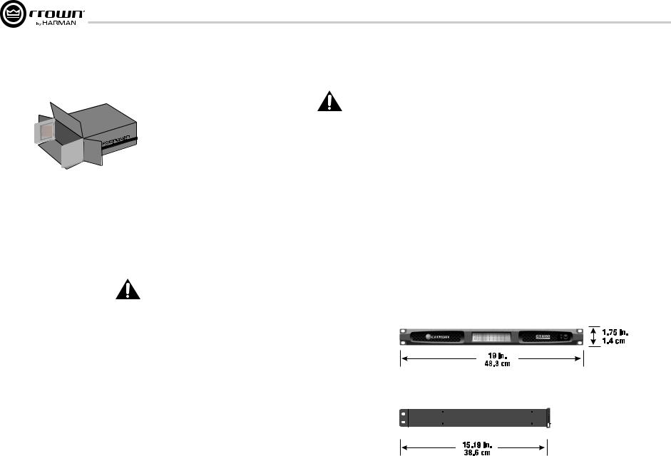
The amplifier is 1.75” tall by 15.19” deep and 19” wide (see figure 4.2.1).
Mount the unit in a standard 19-inch (48.3-cm) equipment rack (EIA RS-310B). You can also place a single amp on a solid, stable surface or stack multiple amps.
NOTE: When transporting, amplifiers should be supported at both front and back.
When using an equipment rack, mount units directly on top of each other. Close any open spaces in the rack with blank panels. DO NOT block front, top or side air vents.
The side walls of the rack should be a minimum of two inches (5.1 cm) away from the amplifier sides, and the back of the rack should be a minimum of four inches (10.2 cm) from the amplifier back panel. While the amplifier is convection cooled and does not require a fan, it is critical that the air vents are not covered.
Figure 4.2.1 CT Series Dimensions
page 6 |
Operation Manual |
CT Power Amplifiers
4 Setup
4.4 Choose Input Wire |
4.5 Choose Output Wire and |
and Connectors |
Connectors |
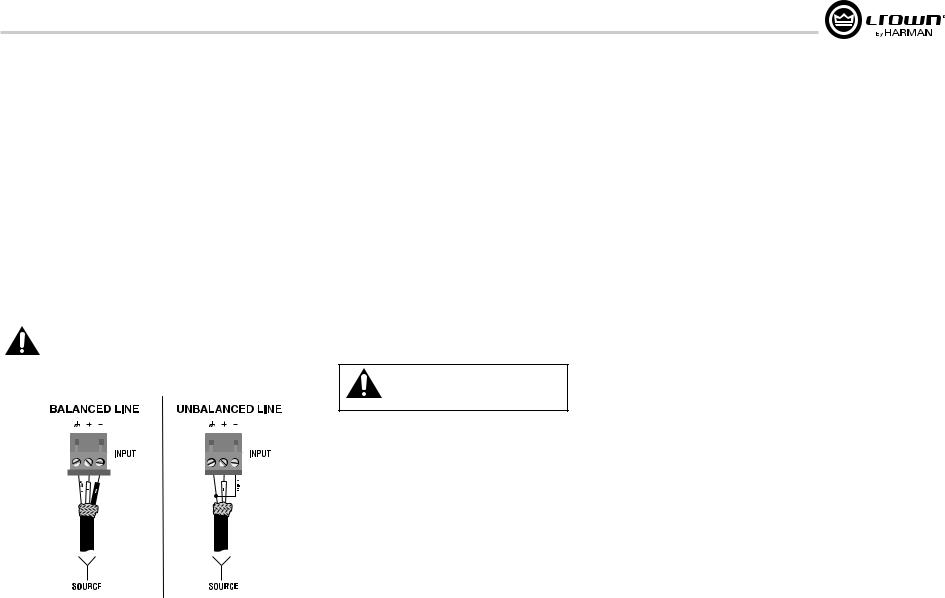
Crown recommends using pre-built or professionally wired balanced line (twoconductor plus shield). Balanced wiring provides better rejection of unwanted noise and hum but unbalanced line may also be used. For more information, refer to the Crown Amplifier Application Guide, available online at www. crownaudio.com.
Use 3-pin Phoenix-type cable ends at the amp input connectors.
Figure 4.4.1 shows connector pin assignments for balanced wiring and figure 4.4.2 shows connector pin assignments for unbalanced wiring.
NOTE: Custom wiring should only be performed by qualified personnel. Class 2 wiring is required.
Crown recommends using professionally constructed, high quality, two-conductor, heavy gauge speaker wire and connectors. Use 2-pin Phoenix-type connectors (Included with the amp).
Suggested below are guidelines to select the appropriate size of wire based on the distance from amplifier to speaker. Check with local code as this may vary.
Distance |
Wire Size |
up to 25 ft. (7.6m) |
16 AWG |
26-40 ft. (7.9-12.2m) |
14 AWG |
CAUTION: Never use shielded cable for output wiring.
CAUTION: Never connect the speaker return to the chassis of the amplifier, or damage to the amplifier may result.
CAUTION: Output of amplifier channels cannot be bridged. This may damage the amplifier.
Figure 4.4.1 |
Figure 4.4.2 |
Operation Manual |
page 7 |
4 Setup
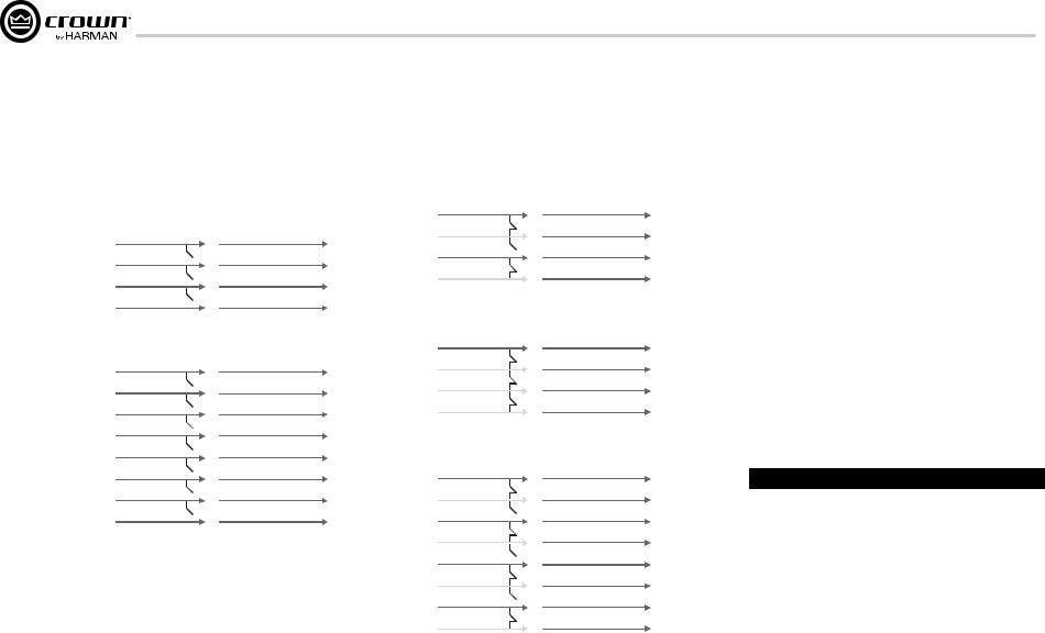
4.6 WireYour System
Before you wire your system, you must be familiar with the capabilities of the input routing.
The DriveCore amplifier can be configured in two ways:
1. The input for a channel goes out the same channel. This option is the standard configuration.
CHANNEL 1 |
RIVED |
CHANNEL 1 |
||
|
|
|
|
|
CHANNEL 2 |
|
|
OREC |
CHANNEL 2 |
|
||||
|
|
|
|
|
CHANNEL 3 |
|
|
MPLIFIERA |
CHANNEL 3 |
|
||||
CHANNEL 4 |
|
|
CHANNEL 4 |
|
|
|
|
||
|
|
|
|
|
Figure 4.6.1 Four channels with no input routing
CHANNEL 1 |
RIVED |
CHANNEL 1 |
||
|
|
|
|
|
CHANNEL 2 |
|
|
OREC |
CHANNEL 2 |
|
||||
|
|
|
|
|
CHANNEL 3 |
|
|
MPLIFIERA |
CHANNEL 3 |
|
||||
CHANNEL 4 |
|
|
CHANNEL 4 |
|
|
|
|
||
CHANNEL 5 |
|
|
|
CHANNEL 5 |
|
|
|||
CHANNEL 6 |
|
|
|
CHANNEL 6 |
|
|
|||
CHANNEL 7 |
|
|
|
CHANNEL 7 |
|
|
|||
CHANNEL 8 |
|
|
|
CHANNEL 8 |
|
|
|||
|
|
|
|
|
Figure 4.6.2 Eight channels with no input routing
page 8
2. The input for a channel can be routed to the next channel, overriding the wired input signal for that channel. This method simplifies input wiring and minimizes use of y-cables.
CHANNEL 1 |
RIVED |
CHANNEL 1 |
|||
CHANNEL 2 |
CHANNEL 2 |
||||
OREC |
|||||
|
|
|
|
||
CHANNEL 3 |
|
|
MPLIFIERA |
CHANNEL 3 |
|
|
|||||
CHANNEL 4 |
CHANNEL 4 |
||||
|
|||||
|
|
|
|
|
|
Figure 4.6.3 Two channel to four channel routing
CHANNEL 1 |
RIVED |
CHANNEL 1 |
|
CHANNEL 2 |
CHANNEL 2 |
||
OREC |
|||
|
|
||
CHANNEL 3 |
MPLIFIERA |
CHANNEL 3 |
|
CHANNEL 4 |
CHANNEL 4 |
||
|
|||
|
|
|
Figure 4.6.4 One channel to four channel routing
CHANNEL 1 |
RIVED |
CHANNEL 1 |
|||
CHANNEL 2 |
CHANNEL 2 |
||||
OREC |
|||||
|
|
|
|
||
CHANNEL 3 |
|
|
MPLIFIERA |
CHANNEL 3 |
|
|
|||||
CHANNEL 4 |
CHANNEL 4 |
||||
|
|||||
CHANNEL 5 |
|
|
|
CHANNEL 5 |
|
|
|
||||
CHANNEL 6 |
|
CHANNEL 6 |
|||
CHANNEL 7 |
|
|
|
CHANNEL 7 |
|
|
|
||||
CHANNEL 8 |
|
CHANNEL 8 |
|||
|
|
|
|
|
|
Figure 4.6.5 Four channel to eight channel routing
Input routing is configured using the dip switches on the back of the amplifier. See Section 11 Input Routing for information on configuring switches.
Note: ComTech DriveCore amplifiers can NOT be bridged.
CT Power Amplifiers
4.7 Connect to AC Mains
Connect your amplifier to the AC mains power source (power outlet) with the supplied AC power cordset. First, connect the IEC end of the cordset to the IEC connector on the amplifier; then, plug the other end of the cord set to the AC mains.
WARNING: The third prong of this connector (ground) is an important safety feature. Do not attempt to disable this ground connection by using an adapter or other methods.
Amplifiers don’t create energy. The AC mains voltage and current must be sufficient to deliver the power you expect. If the AC line voltage varies out of an acceptable range, the amplifier’s power supply turns off and the blue Power LED flashes. The amplifier will turn back on when the AC line voltage returns to safe operating levels.
Figure 4.7.1 provides voltage limits for all amplifier AC voltage configurations. Also, the amplifier must be run within the specified mains frequency requirements (indicated on the amplifier’s back panel label). If you are unsure of the output voltage of your AC mains, please consult your electrician.
Model |
Under-Voltage Limit |
Over-Voltage Limit |
|
|
|
All Models |
90 VAC |
264 VAC |
|
|
|
Figure 4.7.1 AC Under-Voltage and Over-Voltage Limits for Various Amplifier Models
Operation Manual

CT Power Amplifiers
4 Setup
4.8 Startup Procedure
Use the following procedure when first turning on your amplifier:
1.Turn down the level of your audio source.
2.Turn down the level controls of the amplifier (see Section 7.6).
3.Turn on the “Power” switch. The Power indicator should glow.
4.Turn up the level of your audio source to an optimum level.
5.Turn up the Level controls on the amplifier until the desired loudness or power level is achieved.
If you ever need to make any wiring or installation changes, don’t forget to turn off the amplifier and disconnect the power cord.
For help with determining your system’s optimum gain structure (signal levels) please refer to the Crown
Amplifier Application Guide, available online at www.crownaudio.com.
5 Precautions
Your amplifier is protected from internal and external faults, but you should still take the following precautions for optimum performance and safety:
1.Before use, your amplifier first must be configured for proper operation, including input and output wiring hookup. Improper wiring can result in serious operating difficulties. For information on wiring and configuration, please consult the Setup section of this manual or, for advanced setup techniques, consult Crown’s Amplifier Application Guide available online at www.crownaudio.com.
2.Use care when making connections, selecting signal sources and controlling the output level. The load you save may be your own!
3.Do not short the ground lead of an output cable to the input signal ground. This may form a ground loop and cause oscillations.
4.Never connect the output to a power supply, battery or power main. Electrical shock may result.
5.Tampering with the circuitry, or making unauthorized circuit changes may be hazardous and invalidates all agency listings.
6.Do not operate the amplifier with the red Clip LEDs constantly flashing.
7.Do not overdrive the mixer, which will cause clipped signal to be sent to the amplifier. Such signals will be reproduced with extreme accuracy, and loudspeaker damage may result.
8.Do not operate the amplifier with less than the rated load impedance. Due to the amplifier’s output protection, such a configuration may result in premature clipping and speaker damage.
9.Output of amplifier cannot be bridged or multiple channels cannot be connected together.
Remember: Crown is not liable for damage that results from overdriving other system components.
Operation Manual |
page 9 |
 Loading...