


I-Tech 4x3500 HD DriveCoreSeries
Operation Manual |
I-T 4x3500 HD |
Obtaining Other Language Versions: To obtain information in another language about the use of this product, please contact your local Crown Distributor. If you need assistance locating your local distributor, please contact Crown at 574-294-8000.
This manual does not include all of the details of design, production, or variations of the equipment. Nor does it cover every possible situation which may arise during installation, operation or maintenance.
The information provided in this manual was deemed accurate as of the publication date. However, updates to this information may have occurred. To obtain the latest version of this manual, please visit the Crown website at www.crownaudio.com.
Trademark Notice: Crown, Crown Audio, IQ, BCA, and Amcron are registered trademarks of Crown International. HiQnet is a trademark of Harman International Industries, Inc. Other trademarks are the property of their respective owners.
Some models may be exported under the name Amcron.® |
|
©2012 by Harman International, 1718 W. Mishawaka Rd., Elkhart, Indiana 46517-9439 U.S.A. Telephone: 574-294-8000 |
5006082-1 |
|
|
|
9/11 |
I-Tech HD DriveCore Series PowerAmplifiers
Important Safety Instructions |
Wichtige Sicherheitsinstruktionen |
Importantes Instructions de Sécurité |
Instrucciones de Seguridad Importantes |
The I-Tech Series amplifiers are certified only at 120V in Canada.
IMPORTANT
1.Read these instructions.
2.Keep these instructions.
3.Heed all warnings.
4.Follow all instructions.
5.Do not use this apparatus near water.
6.Clean only with a dry cloth.
7.Do not block any ventilation openings. Install in accordance with the manufacturer’s instructions.
8.Do not install near any heat sources such as radiators, heat registers, stoves, or other apparatus (including amplifiers) that produce heat.
9.Do not defeat the safety purpose of the polarized or grounding-type plug. A polarized plug has two blades with one wider than the other. A grounding-type plug has two blades and a third grounding prong. The wide blade or the third prong is provided for your safety. If the provided plug does not fit into your outlet, consult an electrician for replacement of the obsolete outlet.
10.Protect the power cord from being walked on or pinched, particularly at plugs, convenience receptacles, and the point where they exit from the apparatus.
11.Only use attachments/accessories specified by the manufac turer.
12.Use only with a cart, stand, tripod, bracket, or table specified by the manufacturer, or sold with the apparatus. When a cart is used, use caution when moving the cart/apparatus combination to avoid injury from tip-over.
13.Unplug this apparatus during lightning storms or when unused for long periods of time.
14.Refer all servicing to qualified service personnel. Servicing is required when the apparatus has been damaged in any way, such as power-supply cord or plug is damaged, liquid has been spilled or objects have fallen into the apparatus, the apparatus has been exposed to rain or moisture, does not operate normally, or has been dropped.
15.Use the mains plug to disconnect the apparatus from the mains.
16.WARNING: TO REDUCE THE RISK OF FIRE OR ELECTRIC SHOCK, DO NOT EXPOSE THIS APPARATUS TO RAIN OR MOISTURE.
17.DO NOT EXPOSE THIS EQUIPMENT TO DRIPPING OR SPLASHING AND ENSURE THAT NO OBJECTS FILLED WITH LIQUIDS, SUCH AS VASES, ARE PLACED ON THE EQUIPMENT.
18.THE MAINS PLUG OF THE POWER SUPPLY CORD SHALL REMAIN READILY OPERABLE.
To prevent electric shock do not remove top or bottom covers. No user serviceable parts inside. Refer servicing to qualified service personnel.
ÀPRÉVENIR LE CHOC ÉLECTRIQUE N’ENLEVEZ PAS LES COUVERCLES. IL N’Y A PAS DES PARTIES SERVICEABLE
ÀL’INTÉRIEUR. TOUS REPARATIONS DOIT ETRE FAIRE PAR PERSONNEL QUALIFIÉ SEULMENT.
PARA PREVENIR UN CHOQUE ELÉCTRICO, NO RETIRE LAS CUBIERTAS SUPERIOR O INFERIOR. NO EXISTEN PARTES QUE PUEDAN SER REPARADAS POR EL USUARIO AL INTERIOR. REMITA EL SERVICICO AL PERSONAL TÉCHNICAL CALIFICADO.
TO COMPLETELY DISCONNECT THIS EQUIPMENT FROM THE AC MAINS, DISCONNECT THE POWER SUPPLY CORD PLUG FROM THE AC RECEPTACLE. THE MAINS PLUG OF THE POWER SUPPLY CORD SHALL REMAIN READILY OPERABLE.
POUR DÉMONTER COMPLÈTEMENT L’ÉQUIPEMENT DE L’ALIMENTATION GÉNÉRALE, DÉMONTER LE CÂBLE D’ALI MENTATION DE SON RÉCEPTACLE. LA PRISE D’ALIMENTATION RESTERA AISÉMENT FONCTIONNELLE.
PARA DESCONECTAR COMPLETAMENTE EL EQUIPO DEL SUMINSTRO ELECTRICO, DESCONECTE EL CABLE DE ALI MENTACION DE LA TOMA DE CA. LAS PATAS DEL CONECTOR DEL CABLE DE ALIMENTACIÓN DEBERAN MANTENERSE EN BUEN ESTADO.
WATCH FOR THESE SYMBOLS:
The lightning bolt triangle is used to alert the user to the risk of electric shock.
The exclamation point triangle is used to alert the user to important operating or maintenance instructions.
REGARDEZ CES SYMBOLES:
La triangle avec le sigle ‘’foudre’’ est employée pour alerter l’utilisateur au risque de décharge électrique. Le triangle avec un point d’exclamation est employée pour alerter l’utilisateur d’instruction importantes pour lors opérations de maintenance.
ATENCION CON ESTOS SÍMBOLOS:
El triángulo con el símbolo de rayo eléctrico es usado para alertar al usuario de el riesgo de un choque eléctrico.
El triángulo con el signo de admiración es usado para alertar al usuario de instrucciones importantes de operación o man tenimiento.
I-Tech Series amplifiers require Class 2 output wiring.
Les amplificateurs de série de I-Tech exigent des câbles de sortie de classe 2.
I-Tech-Reihe-Verstärker verlangen Klasse die 2 Produktionsverdrah tung.
Los amplificadores de la Serie I-Tech requieren de un cableado de salida Clase 2.
Magnetic Field
CAUTION! Do not locate sensitive high-gain equipment such as preamplifiers directly above or below the unit. Because this amplifier has a high power density, it has a strong magnetic field which can induce hum into unshielded devices that are located nearby. The field is strongest just above and below the unit.
If an equipment rack is used, we recommend locating the amplifiers) in the bottom of the rack and the preamplifier or other sensitive equipment at the top.
FCC COMPLIANCE NOTICE
This device complies with part 15 of the FCC rules. Operation is subject to the following two conditions: (1) This device may not cause harmful interference, and (2) this device must accept any interference received, including interference that may cause undesired operation.
CAUTION: Changes or modifications not expressly approved by the party responsible for compliance could void the user’s authority to operate the equipment.
NOTE: This equipment has been tested and found to comply with the limits for a Class B digital device, pursuant to part 15 of the FCC Rules. These limits are designed to provide reasonable protection against harmful interference in a residential installation. This equipment generates, uses, and can radiate radio frequency energy and, if not installed and used in accordance with the instruction manual, may cause harmful interference to radio communications. However, there is no guarantee that interference will not occur in a particular installation. If this equipment does cause harmful interference to radio or television reception, which can be determined by turning the equipment off and on, the user is encouraged to try to correct the interference by one or more of the following measures:
•Reorient or relocate the receiving antenna.
•Increase the separation between the equipment and receiver.
•Connect the equipment into an outlet on a circuit different from that to which the receiver is connected.
•Consult the dealer or an experienced radio/TV technician for help.
page 2 |
Operation Manual |

I-Tech HD DriveCore Series PowerAmplifiers
Harman International
DECLARATION of CONFORMITY
ISSUED BY: Harman International |
FOR COMPLIANCE QUESTIONS ONLY: |
Sue Whitfield |
1718 W. Mishawaka Road |
|
sue.whitfield@harman.com |
Elkhart, Indiana 46517 U.S.A. |
|
|
|
|
|
Representative’s Name and Address: |
|
|
David Budge |
|
|
10 Harvest Close |
|
|
Yateley, GU46 6YS |
|
|
United Kingdom |
|
|
Equipment Type: Commercial Audio Power Amplifiers
Family Name: I-Tech HD
Model Names: I-TECH4x3500S HD and I-TECH4x3500B HD
EMC Standards:
EN 55103-1:2009 EMC Compatibility – Product Family Standard for Audio, Video, Audio-Visual and Entertainment Lighting Control Apparatus for Professional Use, Part 1: Emissions
EN 55103-1:2009 Magnetic Field Emissions-Annex A @ 10 cm and 20 cm
EN 61000-3-2:2006 Limits for Harmonic Current Emissions (equipment input current less than or equal to 16A
EN 61000-3-3:2008 Limitation of Voltage Fluctuations and Flicker in Low-Voltage Supply systems Rated Current less than or equal to 16A
EN 55022:2010 Limits and Methods of Measurement of Radio Disturbance Characteristics of ITE: Radiated & Conducted, Class B Limits
EN 55103-2:2009 EMC Compatibility – Product Family Standard for Audio, Video, Audio-Visual and Entertainment Lighting Control Apparatus for Professional Use, Part 2: Immunity
EN 61000-4-2:2008 Ed 2.0 EMC Compatibility – Product Family Standard for Audio, Video, Audio-Visual and Entertainment Lighting Control Apparatus for Professional Use, Part 2: Immunity
EN 61000-4-3:2010 Ed 3.2 Radiated, Radio-Frequency, Electromagnetic Immunity (Environment E2, criteria A)
EN 61000-4-4:2007 Radiated, Radio-Frequency, EMC Immunity (Environment E2, Criteria A)
EN 61000-4-5:2006 Surge Immunity (Criteria B)
EN 61000-4-6:2006 Immunity to Conducted Disturbances Induced by Radio-Frequency Fields (Criteria A)
EN 61000-4-11:2004 Voltage Dips, Short Interruptions and Voltage Variation
Safety Standard:
IEC 60065:2001 Ed 7 +A1:2005 Safety Requirements – Audio, Video, and Similar Electronic Apparatus
CAN/CSA 60065-03 incl. A1 Safety Requirements – Audio, Video, and Similar Electronic Apparatus
UL Std No. 60065-2007 Safety Requirements – Audio, Video, and Similar Electronic Apparatus
I certify that the product identified above conforms to the requirements of the EMC Council Directive 2004/108/EC and the Low Voltage Directive 2006/95/EC.
Signed |
|
|
Date of Issue: February 1, 2012 |
|
|
|
|
|
Terry Davenport |
||
|
Title: Sr. Director of Operations |
||
Operation Manual Due to line current harmonics, we recommend that you contact your supply authority before connection. page 3

I-Tech HD DriveCore Series PowerAmplifiers
Table of Contents
Important Safety Instructions ............................................................. |
2 |
7.3 Presets.................................................................................... |
27 |
14.8 LevelMAX Tranducer Thermal Limiters.................................. |
57 |
Declaration of Conformity.................................................................. |
3 |
7.4 List of Pop-Up and Descriptions.............................................. |
28 |
14.9 Thermal Voltage (VRMS)....................................................... |
57 |
Table of Contents............................................................................... |
4 |
7.5 Digital Audio Options (AES3 and VDrive)................................. |
29 |
14.10 Thermal Response Time (s)................................................. |
57 |
1 Welcome ......................................................... |
5 |
7.6 Networking the Amplifier......................................................... |
29 |
15 Appendix B: Table of Parameters Modified by Each Mode |
|
1.1 Features ................................................................................. |
5 |
7.7 SoftwareControllable Onboard DSI........................................ |
29 |
with LevelMAX..................................................... |
58 |
1.2 How to Use This Manual.......................................................... |
5 |
8 Troubleshooting ................................................. |
44 |
16 Application of FIR Filters to Loudspeakers Crossovers... |
60 |
2 Setup .............................................................. |
6 |
9 Specifications.................................................... |
46 |
16.1 FIR Overview......................................................................... |
60 |
2.1 Unpack and Install Your Amplifier ........................................... |
6 |
10 AC Power Draw and Thermal Dissipation................... |
50 |
16.2 What are IIR Filters and FIR Filters?....................................... |
60 |
2.2 Connecting to AC Mains ......................................................... |
7 |
11 Advanced Features............................................. |
51 |
16.3 Pros and Cons of IIR and FIR Filters....................................... |
60 |
2.3 Wire Inputs and Outputs ......................................................... |
7 |
11.1 Protection Systems............................................................... |
51 |
16.4 Desirable Attributes of FIR Filters........................................... |
60 |
3 HARMAN GreenEdge - Going ‘Green’ ........................ |
11 |
11.2 Global Switching Power Supply with PFC.............................. |
51 |
16.5 High Rolloff and Steep Slopes............................................... |
61 |
3.1 Going ‘Green’........................................................................... |
11 |
11.3 6th Generation Class I Circuitry............................................. |
51 |
16.6 Stop-band Attenuation.......................................................... |
61 |
3.2 The Sound of Efficiency .......................................................... |
11 |
11.4 Color-Coded Rear Overlay..................................................... |
51 |
16.7 FIR Polar Lobing Eror............................................................ |
61 |
3.3 Green Savings ........................................................................ |
11 |
12 Appendix A: Network and CobraNet Basics................. |
52 |
16.8 Crown’s Implementation of FIR Filters.................................... |
61 |
4 Integraded DriveCoreTM Technology........................... |
12 |
12.1 HiQnet Networks................................................................... |
52 |
16.9 FFT Convolution................................................................... |
61 |
5 Powered by Crown............................................... |
13 |
12.2 A Closer Look at CobraNet..................................................... |
52 |
16.10 Filter Design........................................................................ |
61 |
6 Operation......................................................... |
14 |
13 LevelMAXTM Limiter Suite..................................... |
56 |
16.11 Low Latency 96 kHz Studio Quality Filters........................... |
62 |
6.1 Protecting Your Speakers ........................................................ |
14 |
14 LevelMAX Limiters............................................. |
57 |
16.12 Measurements of Two-way Loudspeaker System................. |
62 |
6.2 Startup Procedure ................................................................... |
14 |
14.1 LevelMAX Peak Limiter......................................................... |
57 |
16.13 FIR Measurements.............................................................. |
64 |
6.3 Precautions............................................................................. |
14 |
14.2 Peak Limiter Threshold (Vpk)................................................ |
57 |
16.14 Conclusions........................................................................ |
65 |
6.4 Front Panel Controls and Indicators......................................... |
15 |
14.3 Peak Limiter Attach (sec)....................................................... |
57 |
17 Service.......................................................... |
66 |
6.5 Back Panel Controls, Indicators and Connectors..................... |
16 |
14.4 Peak Limiter Release (sec)..................................................... |
57 |
17.1 International and Canada Service........................................... |
66 |
7 Advanced Operation............................................. |
17 |
14.5 Peak Limiter Look Ahead....................................................... |
57 |
17.2 US Service............................................................................ |
66 |
7.1 Introduction............................................................................. |
17 |
14.6 Level MAX RMS Limiter........................................................ |
57 |
18 Warranty......................................................... |
67 |
7.2 Operation Example.................................................................. |
18 |
14.7 RMS Threshold (VRMS)........................................................ |
57 |
|
|
page 4 |
Operation Manual |
I-Tech HD DriveCore Series PowerAmplifiers
I-T4x3500HD |
20 Hz - 20 kHz |
1 kHz 20ms Burst |
2-ohm |
2,100W |
3,500W |
2.7-ohm |
2,200W |
3,800W |
4-ohm |
2,400W |
4,000W |
8-ohm |
1,900W |
1,900W |
4-ohm Bridge |
4,200W |
7,000W |
8-ohm Bridge |
4,800W |
6,000W |
70Vrms Direct |
2,100W |
|
100Vrms Direct |
2,300W |
|
Minimum power in watts with 0.35% THD, all channels driven.
Operation Manual
1 Welcome
The Crown® I-Tech HD DriveCore Series offers amazing power, light weight and ease of use for touring sound applications. Unlike other amplifiers, it includes onboard high-definition DSP, a 4.3” LCD TFT Capacitive Touchscreen, and a built-in network connection.
Modern power amplifiers are sophisticated pieces of engineering capable of producing extremely high power levels. They must be treated with respect and correctly installed if they are to provide the many years of reliable service for which they were designed.
In addition, I-Tech Series amplifiers include a number of features which require some explanation before they can be used to their maximum advantage.
Please take the time to study this manual so that you can obtain the best possible service from your amplifier.
1.1 Features
•Global Power Supply with PFC (Power Factor
Correction) works anywhere in the world.
•High power density, up to 12,000 watts in a
2U chassis.
•Output voltage of 185Vpk provides clean transient peaks.
•6th-generation patented Class I (BCA® with Drivecore Technology) circuitry couples power efficiently to the load and provides low AC current draw.
•Onboard high-definition analog devices
Sharc® processor DSP with 24-bit, 192 kHz SHARC A/D and D/A converters. Advanced IIR filters and linear-phase FIR filters.
•Pushbutton presets simplify setup. Custom presets for various loudspeakers can be downloaded.
•AES3 digital audio input with V-Drive.
•EtherCon® Ethernet connector for HiQnet™ control or CobraNet digital audio transport. This “Single Plug” connection allows HiQnet protocol and CobraNet digital audio, and VDrive through the same CAT 5 cable.
•LCD Control Screen is used to adjust the amplifier’s attenuation and muting, configure the amp, set up and view error monitoring, and recall DSP presets to reconfigure the amp for various applications.
•Comprehensive array of indicators provide accurate diagnostics: Power, Data, along with Ready, Signal, Clip, Thermal and Fault for each channel.
•AC mains indicator in power switch glows green when AC power is present.
•Front-panel USB connector accepts a USB drive to transfer presets from the drive to the amplifier DSP, and vice versa. This feature also allows you to update the amplifier’s firmware.
•Light weight due to aluminum chassis, special internal construction, switching power
supply and patented class-I output stage with DriveCore Technology.
•Thermal management controller and two discrete thermal zones with variable-speed fans, forced-air cooling.
•Advanced protection circuitry guards against: shorted outputs, DC, mismatched loads, general overheating, under/over voltage, highfrequency overloads and internal faults.
•Five-Year, No-Fault, Fully Transferable
Warranty completely protects your investment and guarantees its specifications.
1.2 How to Use This Manual
This manual provides you with the necessary information to safely and correctly setup and operate your amplifier. It does not cover every aspect of installation, setup or operation that might occur under every condition. For additional information, please consult the online help in System Architect software, Crown’s Amplifier Application Guide, I-Tech Application Guide (available online at www. crownaudio.com), Crown Technical Support, your system installer or retailer.
We strongly recommend you read all instructions, warnings and cautions contained in this manual. Also, for your protection, please send in your warranty registration card today. And save your bill of sale — it’s your official proof of purchase.
page 5
I-Tech HD DriveCore Series PowerAmplifiers
2 Setup
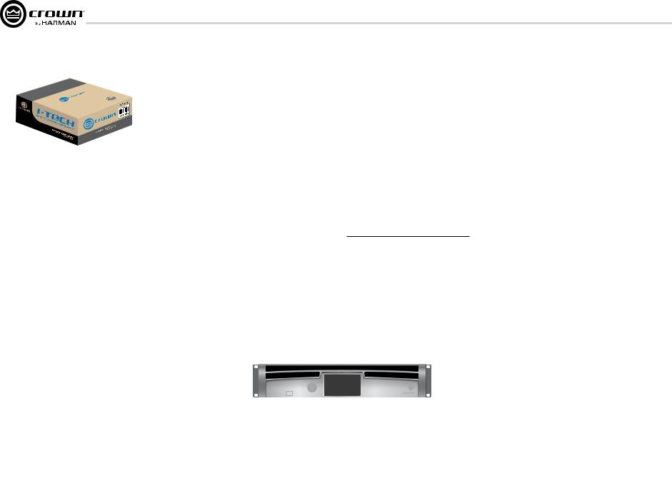
2.1 Unpack and Install Your
Amplifier
Please unpack and inspect your amplifier for any damage that may have occurred during transit. If damage is found, notify the transportation company immediately. Only you can initiate a claim for shipping damage. Crown will be happy to help as needed. Save the shipping carton as evidence of damage for the shipper’s inspection.
We also recommend that you save all packing materials so you will have them if you ever need to transport the unit. Never ship the unit without the factory pack.
YOU WILL NEED (not supplied):
• Input wiring cables
• Output wiring cables
• Ethernet cables
• Rack for mounting amplifier (or a stable surface for stacking)
WARNING: Before you start to set up your amplifier, make sure you read and observe the Important Safety Instruc tions found at the beginning of this manual.
page 6
CAUTION: Before you begin, make sure your amplifier is disconnected from the power source, with the power switch in the “off” position and all level controls turned completely down (counterclock wise).
Use a standard 19-inch (48.3 cm) equipment rack (EIA RS-310B). See Figure 2.1 for amplifier dimensions.
You may also stack amps without using a rack.
NOTE: When transporting, amplifiers should be supported at both front and back.
MAGNETIC FIELD
CAUTION! Do not locate sensitive high-gain equipment such as preamplifiers or tape decks directly above or below the unit. Because this amplifier has a high power density, it has a strong magnetic field which can induce hum into unshielded devices that are located nearby. The field is strongest on the right side and right bottom of the amplifier (facing the amplifier).
If an equipment rack is used, we recommend locating sensitive equipment at least 20 cm (8 inches) away from the amplifier.
3.5 In.
8.9 cm
19 In.
48.3 cm
1.5 In.
3.8 cm
16.95 In.
43.1 cm
Figure 2.1
Dimensions
When using an equipment rack, mount units directly on top of each other. Close any open spaces in rack with blank panels. DO NOT block front or rear air vents. The side walls of the rack should be a minimum of two inches (5.1 cm) away from the amplifier sides, and the back of the rack should be a minimum of four inches (10.2 cm) from the amplifier back panel.
Figure 2.2 illustrates standard amplifier airflow.
Figure 2.2 Airflow
Operation Manual
I-Tech HD DriveCore Series PowerAmplifiers
2 Setup
2.2 Connecting to AC Mains
WARNING: The third (ground) prong of the supplied AC power cord connector is a required safety feature. Do not attempt to disable this ground connection by using an adapter or other methods.
Amplifiers do not create energy. The AC mains voltage and current must be sufficient to deliver the power you expect. You must operate your amplifier from an AC mains power source with not more than a 10% variation above or a 10% variation below the amplifier’s specified line voltage range and within the specified frequency requirements (indicated on the amplifier’s back panel label). If you are unsure of the output voltage of your AC mains, please consult your electrician.
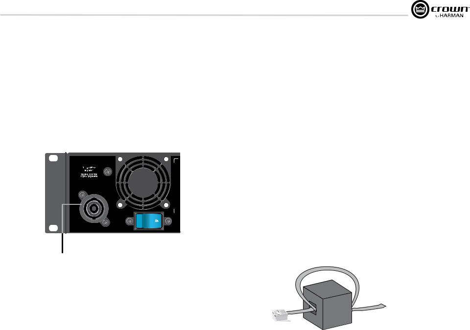
I-TECH 4x3500 | 2300W
CAUTION – TO REDUCE THE RISK
OF ELECTRIC SHOCK, GROUNDING
MUST BE MAINTAINED.
ASSEMBLED IN USA
32A Neutrik® powerCON
Figure 2.3 Power Connector
Operation Manual
2.3 Wire Inputs and Outputs
2.3.1 Wiring basics
•Always use shielded wire for input wiring. The higher the density of the shield (the outer conductor) the better. Spiral wrapped shield is not recommended.
•When using unbalanced lines keep the cables as short as possible. Avoid lengths greater than 10 feet (3 meters).
•Do not run audio input cables together with high-level wiring such as loudspeaker wires or AC cords. (This lessens the chance of hum and noise being induced into the input cables.)
•Turn the entire sound system off before changing any connections.
Crown is not liable for damage incurred when any transducer or component is over driven.
THE CHANNEL 2 AND 4 INPUT IS IGNORED by default in Bridge Mono mode. It can be summed using the input source selector.
For additional information on audio input wiring please refer to the Crown Amplifier Application Guide available online at www.crownaudio.com. It contains helpful information on preventing unwanted subsonic frequencies, radio frequency interference, ground loops, and feedback oscillation.
When using network connections, pass the CAT 5 cable five times through a ferrite core (Figure 2.4), available from Crown Audio Inc. This is to ensure compliance with emission regulations.
Figure 2.4 Pass the CAT 5 Cable Five Times Through the Ferrite Core
page 7
I-Tech HD DriveCore Series PowerAmplifiers
2Setup
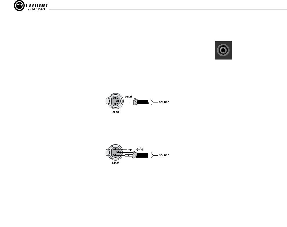
2.3.2Choose Input Wire and Connectors
Crown recommends using pre-built or professionally wired, balanced line (two-conductor plus shield), 22-24 gauge cables and connectors. Use 3-pin male XLR connectors.
Unbalanced line may also be used but may result in noise over long cable runs.
Figure 2.5 shows connector pin assignments for balanced analog wiring or AES3 digital wiring. The use of standard analog cable with AES3 will result in diminished performance. For best results, 110 ohm shielded twisted-pair cable for AES3 signals is highly recommended. Figure 2.6 shows connector pin assignments for unbalanced analog wiring.
If multiple connectors are needed for AES3 distribution from a single AES3 source, the following shows the number of AES connections in parallel based on AES3 switching frequency.
Frequency |
# of Connections |
96kHz |
4 AES3 Pairs |
48kHz |
8 AES3 Pairs |
44.1kHz |
8 AES3 Pairs |
***Please note with good quality 110 ohm shielded digital cable, it is possible to obtain a higher number of connections than stated here. It is up to the user to test this based on their use case. The connections stated here are based on worst case analysis.
NOTE: Custom wiring should only be performed by qualified personnel.
2.3.3 Choose Output Wire and Connectors
Crown recommends using pre-built or professionally wired, highquality, two-, four-, or eight-conductor, heavy gauge speaker wire and connectors. Use Class 2 output wiring. You may use a 4-pole Speakon® connector (Figure 2.7) or banana plugs, spade lugs, or bare wirefor your output connectors (Figure 2.8). To prevent the possibility of short circuits, wrap or otherwise insulate exposed loudspeaker cable connectors.
CAUTION – SHOCK HAZARD: Potentially lethal voltages exist at the output connectors when the amplifier is turned on and is passing a signal.
Using the guidelines below, select the appropriate size of wire based on the distance from amplifier to speaker.
Distance |
Wire Size |
|
|
|
|||
up to 25 ft. |
16 AWG |
|
|
|
|||
26-40 ft. |
14 AWG |
|
|
|
|||
41-60 ft. |
12 AWG |
|
|
|
|||
61-100 ft. |
10 AWG |
|
|
|
|||
|
|
|
|
|
|
|
|
|
|
|
|
|
|
|
|
|
|
|
|
|
|
|
|
|
|
|
|
|
|
|
|
|
|
|
|
|
|
|
|
|
|
|
|
|
|
|
|
|
|
|
|
|
|
|
|
|
|
|
|
|
|
|
|
|
|
|
|
|
|
|
|
Figure 2.5
Balanced Analog Input Connector Wiring or
AES3 Digital Connector Wiring
Figure 2.6 Unbalanced Analog Input Connector Wiring
Figure 2.7
Left: Speakon® Output Connector on Back Panel Right: Speakon® Cable Connector
|
|
|
CH1 |
OUTPUTS |
CH2 |
|
|
|
|
|
|
|
||
|
|
|
|
|
|
|
|
|
|
|||||
|
|
|
|
|
|
|
|
|
|
|||||
|
|
|
DUAL |
BRIDGE |
DUAL |
|
|
|
|
|
|
|
||
|
|
|
|
|
|
|
|
|
|
|
|
|
|
|
|
|
|
|
|
|
|
|
|
|
|
|
|
|
|
|
|
|
|
|
|
|
|
|
|
|
|
|
|
|
DUAL |
BRIDGE |
DUAL |
|
|
|
|
|
CH3 |
|
CH4 |
|
|
|
|
|
|
|
|
|
|
|
||
|
|
|
|
|
|
|
|
|
|
|
|
|
|
|
|
|
|
|
|
|
|
|
|
|
|
|
|
|
|
|
|
Figure 2.8
Binding Post Connections
page 8 |
Operation Manual |
I-Tech HD DriveCore Series PowerAmplifiers
2 Setup
101-150 ft. |
8 AWG |
151-250 ft. |
6 AWG |
CAUTION: Never use shielded cable for output wiring.
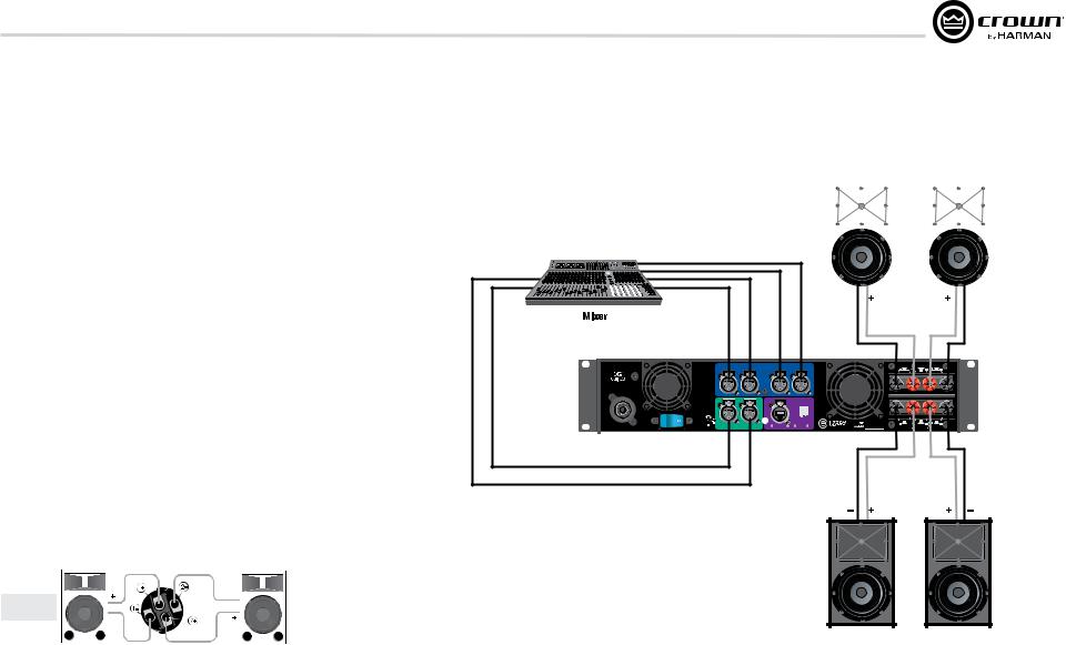
2.3.4 Stereo Mode Wiring
Typical input and output wiring is shown in Figure 2.9.
IMPORTANT: Turn off the amplifier and unplug its power cord.
INPUTS: Choose one of these options:
•Connect analog input wiring for all channels.
•Connect AES3 digital signal to the AES3 connectors.
OUTPUTS: Maintain proper polarity (+/–) on output connectors. Use Class 2 output wiring.
Figure 2.9 shows how to wire stereo speakers to the binding posts. Connect Channel 1 loudspeaker’s positive (+) lead to Channel 1 positive (red) terminal of amp; repeat for negative (–). Repeat Channel 2 wiring as for Channel 1.
To wire stereo speakers to the Speakon® connectors, use this method:
Table 1
Stereo Wiring Method 1: Use Top Speakon® Only
|
|
|
PIN |
1+ |
1– |
2+ |
|
|
2– |
|
|
|||||
|
|
|
|
|
|
|
|
|
|
|
|
|
|
|
|
|
|
|
|
CH |
1+ |
1– |
2+ |
|
|
2– |
|
|
|||||
|
|
|
|
|
|
|
|
|
|
|
|
|
|
|
|
|
|
|
|
|
|
|
|
|
|
|
|
|
|
|
|
|
|
|
|
|
|
|
|
|
|
|
|
|
|
|
|
|
|
|
Channel 1 |
|
|
|
|
|
|
|
|
|
|
|
|
|
Channel 2 |
||
|
|
|
|
|
|
|
|
|
|
|
|
|
||||
|
|
|
|
|
|
|
|
|
|
|
|
|
|
|
|
Loudspeaker |
Loudspeaker |
|
|
|
|
|
|
|
|
|
|
|
|
||||
|
|
|
|
|
|
|
|
|
|
|
|
|
|
|
|
|
|
|
|
|
|
|
|
|
|
|
|
|
|
|
|
|
|
Figure 2.10 Wiring Two Stereo Speakers to the Top Speakon® Connector
I-TECH 4x3500 | 2300W
CAUTION – TO REDUCE THE RISK OF ELECTRIC SHOCK, GROUNDING MUST BE MAINTAINED.
1 |
|
2 |
|
3 |
4 |
Channel |
|
Channel |
|
Channel |
Channel |
CH1 |
CH2 |
ANALOG |
CH3 |
|
CH4 |
|
|
INPUTS |
|
|
|
CH |
NETWORK |
3/4 |
|
|
Channel 1 |
|
|
Channel 2 |
||||
|
|
|
|
|
|
|
|
|
|
|
|
|
|
|
|
|
|
|
|
|
|
|
|
|
|
|
|
|
|
|
|
|
|
|
|
5,657,219 |
7,283,379 |
7,521,936 |
CH1 |
OUTPUTS |
CH2 |
DUAL |
BRIDGE |
DUAL |
|||
REG. U.S. PAT. OFF. |
6,504,348 6,909,321 |
7,557,622 7,919,998 7,778,324 |
CLASS 2 OUTPUT WIRING |
|
|
|
CH |
|
|
DATA |
PRESET |
DUAL |
BRIDGE |
DUAL |
ASSEMBLED IN USA |
1/2 |
DIGITAL INPUT AES3 |
COND. |
LINK/ |
|
CH3 |
|
CH4 |
|
ACT. |
|
|
|||||
AES 1+2 |
|
|
|
|
|
|
|
|
AES 3+4 |
|
|
|
|
|
|
|
|
Figure 2.9
System Wiring,
2 x Stereo Mode
Channel 3 |
Channel 4 |
Operation Manual |
page 9 |
I-Tech HD DriveCore Series PowerAmplifiers
2 Setup
Table 1 and Figure 2.10: Wire one Speakon® cable connector to two speakers. Insert the Speakon® cable connector into the amplifier’s top Speakon® connector.
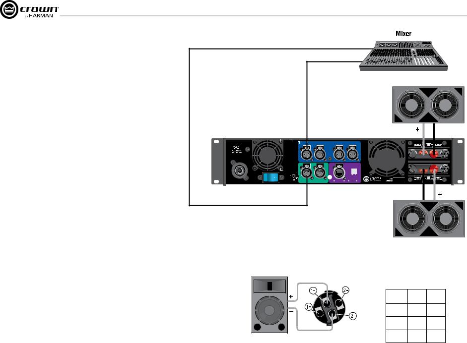
2.3.5 Bridge-Mono Mode
Overview: Turn on the amp, enable Bridge-Mono mode using the LCD Control Screen, turn off the amp, wire it, and turn it back on.
1.Be sure that no cables are connected to the amplifier. Turn on the front-panel power switch. The LCD Control Screen will light up.
2.Under the LCD Control Screen, press the Menu/Exit button. Press the Next button until you see OUTPUT MODE on the screen. If N/A is displayed, OUTPUT MODE is locked via software. If LOCKOUT is displayed, all the LCD screens are locked via software.
3.Press the Encoder knob to select BRIDGE MONO. Press the knob again to confirm your choice. Press Menu/Exit. Turn down both level controls (Encoder) until you reach maximum attenuation.
4.IMPORTANT: Turn off the amplifier and unplug its power cord.
INPUTS: There are three ways to connect an input signal to the amplifier (Figure 2.11):
•Connect an analog signal source to the Channel-1 and/or Channel-3 amplifier input.
•Connect an AES/EBU digital signal source to the Digital Input IN connector.
NOTE: Crown provides a reference of wiring pin assignments for commonly used connector types in the Crown Amplifier Application Guide available at www.crownaudio.com.
OUTPUTS: Use Class 2 output wiring. There are two ways to wire the amplifier output connectors for Bridge-Mono mode:
1) Wire the speaker across the red binding post channels 1/2 and 3/4 (Figure 2.11). Do not use the black binding posts when operating in Bridge-Mono mode.
NOTE: In Bridge-Mono mode, the Channel 1 Level control sets the level; the Channel 2 Level control is defeated. All Channel 2 objects and controls are hidden and disabled. In this mode, the Channel 3 Level control sets the level; the Channel 4 Level control is defeated.
AES
Analog
I-TECH 4x3500 | 2300W
CAUTION – TO REDUCE THE RISK
OF ELECTRIC SHOCK, GROUNDING
MUST BE MAINTAINED.
ASSEMBLED IN USA
Figure 2.11
System Wiring,
2 x mono mode
CH1 |
CH2 |
ANALOG |
CH3 |
CH4 |
|
|
INPUTS |
|
|
CH |
NETWORK |
3/4 |
|
CH |
|
|
DATA |
PRESET |
1/2 |
DIGITAL INPUT AES3 |
COND. |
LINK/ |
|
|
ACT. |
|
5,657,219 |
7,283,379 |
7,521,936 |
REG. U.S. PAT. OFF. |
6,504,348 6,909,321 |
7,919,998 7,778,324 |
|
|
7,557,622 |
|
OUTPUTS |
|
|
CH1 |
CH2 |
||
DUAL |
BRIDGE |
DUAL |
|


 CLASS 2 OUTPUT WIRING


DUAL |
BRIDGE |
DUAL |
|
CH3 |
|
CH4 |
|
|
|
|
|
|
|
Table 2 |
|
|
Speakon® Wiring for Bridge-Mono |
||
|
PIN |
1+ |
2+ |
|
SPKR |
+ |
– |
|
PIN |
3+ |
4+ |
Figure 2.12 |
SPKR |
+ |
– |
|
|
|
|
Mono Wiring Using Both |
|
|
|
page 10 |
Operation Manual |
I-Tech HD DriveCore Series PowerAmplifiers
3 HARMAN GreenEdge -Going ‘Green’ without compromise
3.1 Going ‘Green’
Going ‘Green’ is no longer an option – it’s a necessity. Protecting the world we live in against adverse climate change is a major objective of socially responsible governments, businesses and individuals everywhere. Reducing energy consumption is fundamental to the reduction of greenhouse-gas emissions and is likely to impact various elements of our lifestyle. Maintaining the quality of our lifestyle, while improving the environment, is a challenge addressed by the HARMAN GreenEdge advanced technology initiative.
HARMAN’s passion for innovative engineering remains dedicated to its goal of acoustic excellence for all of its products. HARMAN’s loyal customers never need to fear the loss of performance from going ‘Green’ – in fact, the new range of GreenEdge audio systems enhance performance and acoustic qualities. HARMAN continues to drive the importance of ‘the listening experience’ while caring for the world we share.
3.2 The Sound of Efficiency
HARMAN’s Research and Development teams are implementing highly innovative engineering, design and manufacturing processes across its range of world-class branded audio and infotainment products. The GreenEdge technology initiative allows partners to take advantage of Eco-Friendly, energy-saving benefits such as:
Weight Savings -When compared to traditional, non-switching amplifiers, the I-Tech HD Series weighs an average of 50 lbs (22.68kg) less. Less weight benefits the consumer by reducing shipping costs and benefits the environment by reducing emissions from vehicles because the shipper is able to either reduce the amount of vehicles needed to transport the goods or the vehicle is not running up to its weight limits resulting in less fuel economy.
High-Efficiency Designs – The patented Universal Power Supply with Power Factor Correction combined with the patented Class-I PWM output stage of the I-Tech HD series amplifiers provides greater than 90% efficiency when ran at 100VAC to 240VAC and all voltage in between.
Power Savings – The I-Tech HD Series has both manual and automatic standby modes that put the amplifier into a low AC current draw state when not in use. When in this mode, the I-Tech HD series draws an average of 100W of power greatly reducing your power bills.
Environmental Responsibility – By integrating HARMAN GreenEdge systems into your business model, you are promoting Eco-Friendly energy saving initiatives and reducing your impact on the enviorment.
Operation Manual
3.3 Green Savings
Here’s an example of the energy savings offered by Crown’s Class-I tour products:
Class-I Amplifiers v. MA5002VZ in Touring Applications
•If Crown shipped 13,500 IT4000/MA5000/IT5000HD
•If we had shipped 13,500 MA5002VZs in their place, the numbers would look like this:
|
MA5002VZ |
Class-I Tour Amp |
|
(IT4000, MA5000i, IT5000HD) |
|
|
|
|
Number of Units |
13,500 |
13,500 |
|
|
|
Total Weight |
519.8 tons |
189 tons |
|
|
|
1 hour of Electricity Usage |
2.52kWh |
1,602kWh |
|
|
|
1 year of Electricity Usage |
18,370,800 kWh |
11,678,580 kWh |
|
|
|
Electricity Savings:
•~6,692,220 kWh
•Enough to power ~370 households annually!
Weight Savings (Freight):
•Reduces ~400 Metric tons of greenhouse gas annually
•About the same as taking 75 cars off the road
page 11
I-Tech HD DriveCore Series PowerAmplifiers
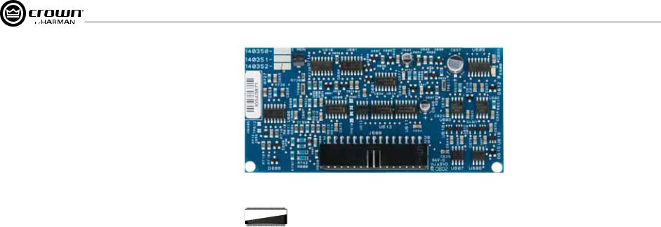
4 Integrated DriveCoreTM Technology
Class D and Class I amplifiers are notable for extraordinarily high efficiency and being well suited for driving difficult reactive loads such as subwoofers.
Crown engineers developed DriveCore™ Technology – a proprietary hybrid analog-digital integrated circuit (IC) developed with Texas Instruments that drives the “front end” of the Class D or Class I output stage. Over 60 years of Crown’s design knowledge and experience went into the development of this technology resulting in truly remarkable benefits.
DriveCore™ Technology provides an extremely wide-tolerance with regards to sagging or “dirty” AC line conditions providing consistent performance without affecting audio quality. This means that your performance will not be compromised by fluctuating generator power or overloading by lighting rigs, backline gear, etc.
In addition, DriveCore™ Technology’s patented feedback and PWM modulation circuits enable fast recovery on peak transients, accurate reproduction of low-level detail, and precise tracking of lowfrequencies at high power levels for maximum subwoofer output.
Figure 4.1 I-Tech HD 2 Channel Front End Board
 07CYDJKL
SN61112B5
Figure 4.2 Ruby Chip (Actual Size)
page 12 |
Operation Manual |
I-Tech HD DriveCore Series PowerAmplifiers
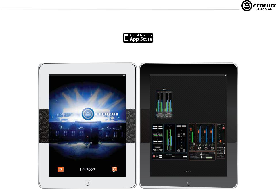
5 Powered by Crown
This I-Tech HD Series amplifier is compatible with the Powered by Crown app. For more information visit: http://www.crownaudio.com/mobileapplications/index.htm
iPad
Operation Manual
iPad
The New System Control App from Crown,
Available at the Apple App Store.
+Instantly connect to your Crown networked amps; just plug your amps into any wireless router, watch the amps auto-populate, and you have full control of everything
+Watch over your entire rig using your IPhone or IPad, anywhere in the venue - intuitive control panels allow you to monitor input levels, output levels, thermal conditions - anything you need
+Need to limit control or see something special? Choose any controls you want using System Architect custom panels; then easily import them using ITunes
+Use it with CTs, I-Tech, I-Tech HD, and Macro Tech I series (CTs requires network PIP)
Input |
LOW |
MID |
HIGH |
Signal Generator |
LLevels/Mute/ ute
Available right now, download instantly from the Apple App Store.
Visit crownaudio.com for more information
page 13

I-Tech HD DriveCore Series PowerAmplifiers
6Operation
6.1Protecting Your Speakers
It’s wise to avoid clipping amplifier signals at the input and output. Not only does clipping sound bad, it can damage loudspeakers. To prevent clipping, use System Architect software’s Level Max suite to enable or display the peak voltage limiter and average power limiter in your amplifier’s built-in DSP. That way, no matter how strong a signal your mixer produces, the amplifier output will not clip. Set the limiter threshold so that at full level no components in the audio signal chain are clipping, the amplifier input and output is not clipping, and the attached loudspeakers at properly protected according to the mnfg’s rec’d specifications.
Also, avoid sending strong subsonic signals to the amplifier. Highlevel, low-frequency signals from breath pops or dropped micro phones can blow out drivers. To prevent subsonic signals, use one of these methods:
•Insert a highpass filter between mixer output and amplifier input (or between mixer and limiter).
•Use the I-Tech’s onboard DSP to set up a highpass filters.
•Switch in highpass filters at your mixer. Set the filter to as high a frequency as possible that does not affect your program. For example, try 35 Hz for music and 75 Hz for speech. On each mixer input channel, set the filter frequency just below the lowest fundamental frequency of that channel’s instrument.
•Note: An amplifier reproduces the signal present on the input.
Therefore, if you send clipped or squared wave signals to the input, it will recreate this on the output possibly damaging your loudspeakers.
6.2 Startup Procedure
When first turning on your amplifier, follow the procedures in the Quick-Start Guide on page 4 (stereo) or page 5 (bridge-mono).
If you ever need to make any wiring or installation changes, don’t forget to disconnect the power cord.
For help with determining your system’s optimum gain structure (signal levels) please refer to the Crown Amplifier Application Guide, available online at www.crownaudio.com.
6.3 Precautions
Your amplifier is protected from internal and external faults, but you should still take the following precautions for optimum performance and safety:
1.Before use, your amplifier first must be configured for proper operation, including input and output wiring hookup. Improper wiring can result in serious operating difficulties. For information on wiring and configuration, please consult the Setup section of this manual or, for advanced setup techniques, consult Crown’s
Amplifier Application Guide available online at www.crownaudio.com.
2.Use care when making connections, selecting signal sources and controlling the output level. The load you save may be your own!
3.Do not short the ground lead of an output cable to the input signal ground. This may form a ground loop and cause oscillations.
4.WARNING: Never connect the output to a power supply, battery or power main. Electrical shock may result.
5.Tampering with the circuitry, or making unauthorized circuit changes may be hazardous and invalidates all agency listings.
6.Do not operate the amplifier with the red Clip LEDs constantly flashing.
7.Do not overdrive the mixer, which will cause clipped signal to be sent to the amplifier. Such signals will be reproduced with extreme accuracy, and loudspeaker damage may result.
8.Do not operate the amplifier with less than the rated load impedance. Due to the amplifier’s output protection, such a configuration may result in premature clipping and speaker damage.
9.CAUTION – SHOCK HAZARD: Potentially lethal voltages exist at the output connectors when the amplifier is turned on and is passing a signal.
Remember: Crown is not liable for damage that results from overdriving other system components.
page 14 |
Operation Manual |
I-Tech HD DriveCore Series PowerAmplifiers
6Operation
6.4Front Panel Controls and Indicators
Many of these functions can be disabled using Blackout Mode (a selection in the Advanced Menu, Section 7.2).
A. Cooling Vents
Front-to-rear forced airflow through foam dust filter
B. LCD Control Screen
Integrated 4.3” color touchscreen LCD with backlight, controls amplifier setup and operation.
The LCD Control Screen and its controls let the user adjust the amplifier’s attenuation and muting, configure the amp, set up and view error monitoring (such as temperature and load supervision), and recall DSP presets.
C.Power Switch
Push-on/push-off switch glows green when AC power is present at the power cord and the amplifier circuit breaker is in the “on” position.
D.USB 2.0 Connector
Accepts a USB drive to transfer presets, device files, and update firmware from the drive to the amplifier DSP, and vice versa.
E.Fault Indicator
Red LED, one per channel, flashes when the amplifier output channel has stopped operating. Usually this means that the amplifier must be serviced.
F.Thermal Indicator
Red LED, one per channel, illuminates when the channel has shut down due to thermal stress or overload.
G.Clip Indicator
Red LED, one per channel, illuminates when the channel’s output signal reaches the onset of audible clipping. The Clip Indicator also will illuminate during Thermal Level Control (TLC) limiting. The Clip Indicator can be turned off during Blackout mode.
H. Level Control (Encoder)
Speed-sensitive, 0.5 dB steps, range 0 to –100 dB. This knob affect the Channel 1-4 output levels. Also Menu items and adjust parameter values that are displayed on the LCD control screen.
I. Menu/Exit Button
“Menu” enters the main menu. “Exit” leaves the menu.
J. Prev Button
Selects the previous item in the menu.
K. Next Button
Selects the next item in the menu.
L. Signal Indicators
These can be disabled during Blackout mode. Three green LEDS per channel indicate the amplifier’s input and output signal levels. From top to bottom the LEDs are
–10 dB: amplifier output is 10 dB below clipping. –20 dB: amplifier output is 20 dB below clipping. Signal: selected input signal is above –40 dBu.
M. Ready Indicator
Green LED, one per channel, illuminates when the channel is initialized and ready to produce audio output.
N.Power Indicator
Blue LED indicates amplifier has been turned on and AC power is available. The LED will flash when the AC line voltage is 15% above or below the nominal rated range. This indicator can be turned off in Blackout mode.
O.Data Indicator
Yellow LED indicates network data activity. Data indicator flashes only when the amplifier is polled for data, or is polled to see whether it is online. This indicator can be turned off in Blackout mode.
P.Bridge Mode Indicator
Yellow LED illuminates when the amplifier is set to Bridge-Mono mode.
|
Figure 6.1 Front Panel Controls and Indicators |
Operation Manual |
page 15 |
I-Tech HD DriveCore Series PowerAmplifiers
6 Operation
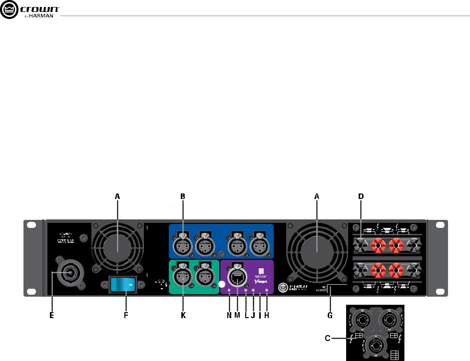
6.5 Back Panel Controls, Indicators
and Connectors
A. Fans
Provide front-to-back forced airflow for cooling.
ANALOG INPUTS SECTION
B. Balanced Analog XLR Inputs
A 3-pin female XLR connector for each channel.
OUTPUTS SECTION
C. Speakon® Output Connectors
Two high-current, 50A Neutrik® Speakon® NL4MLP (mates with NL4FC and NL4), for channels 1+2 or 3+4 and one NLT8 for channels 1 thru 4. Class 2 output wiring required.
These two connectors accept 2-pole or 4-pole Speakon® connectors. See Figures 2.5 through 2.10 and Tables 1, 2 and 3 for connector wiring. The top 2 speakon connectors are wired each for stereo
operation off of one connector, the bottom NL8 speakon connection is for four way operation off of one connector.
D. Binding Post Output Jacks
One pair per channel of high-current, 60A color-coded binding posts. Accepts banana plugs, wire or spade lugs.
E. Power Cord Connector
32 amp PowerCon® AC Inlet. Voltage range is indicated above IEC inlet.
F. Reset Switch/Circuit Breaker
If the current draw of the amplifier exceeds safe limits, this breaker automatically disconnects the power supply from the AC mains. The switch resets the circuit breaker.
G. MAC Address
This specific amplifier’s network identifier that is burned into its firmware.
H. Preset Indicator
LED flashes to signal the number of the current preset if active. LED is green if the preset values have not been changed once loaded. LED is yellow if the preset values have been changed since they were loaded.
I. Reset Button
To restore factory default settings: Press the Reset Button with a thin, non-conductive object, then turn on amplifier power, and continue to hold the reset button until the Preset light comes on green (approximately 16 seconds)..
J. Data Indicator
Flashes yellow only when the amplifier is polled for data, or is polled to see whether it is online.
DIGITAL INPUTS SECTION
K. AES/EBU Digital Input
This 3-pin female XLR connector accepts a digital signal in the AES/EBU format.
It is not recommended to loop through more than four amplifiers. If larger distribution of AES is needed, the use of an AES distribution amplifier is recommended.
NETWORKING SECTION
L. Link/Act Indicator
Shows network activity.The LINK ACT LED illuminates when the network port is connected and flashes when network activity is detected.
M. Network Connector
This EtherCon® Ethernet connector is for networking. Warning: Only connect to networks that remain inside the building.
N. Cond Indicator
Turns on if the amplifier is set to be the CobraNet conductor. The CobraNet conductor is a CobraNet node that provides the master timing clock for the CobraNet digital audio transport network.
I-TECH 4x3500 | 2300W
CAUTION – TO REDUCE THE RISK
OF ELECTRIC SHOCK, GROUNDING
MUST BE MAINTAINED.
ASSEMBLED IN USA
page 16
|
|
INPUTS |
|
|
6,909,321 7,521,936 |
CH1 |
CH2 |
ANALOG |
CH3 |
CH4 |
|
|
|
6,504,348 |
7,778,324 |
|
CH |
NETWORK |
PAT. OFF. 5,657,219 |
7,557,622 7,919,998 |
|
REG.U.S. |
7,283,379 |
|||
3/4 |
|
|||
|
|
|
CH |
|
|
DATA |
PRESET |
1/2 |
DIGITAL INPUT AES3 |
COND. |
LINK/ |
|
|
ACT. |
|
Figure 6.2 Back Panel Controls and Connectors
|
CH1 |
OUTPUTS |
CH2 |
|
DUAL |
BRIDGE |
DUAL |
CLASS 2 OUTPUT WIRING |
|
|
|
|
DUAL |
BRIDGE |
DUAL |
|
CH3 |
|
CH4 |
CH1 / CH2 |
CH3 / CH4 |
|
|
1+/– |
1 |
3+/– |
1 |
2+/– |
2 |
4+/– |
2 |
OUTPUTS |
|
CH1 / CH2 |
|
|
CH3 / CH4 |
||
|
|
||
|
|
1+/– |
1 |
|
|
2+/– |
2 |
|
|
3+/– |
3 |
|
|
4+/– |
4 |
Operation Manual
I-Tech HD DriveCore Series PowerAmplifiers
7 Advanced Operation
7.1 Introduction
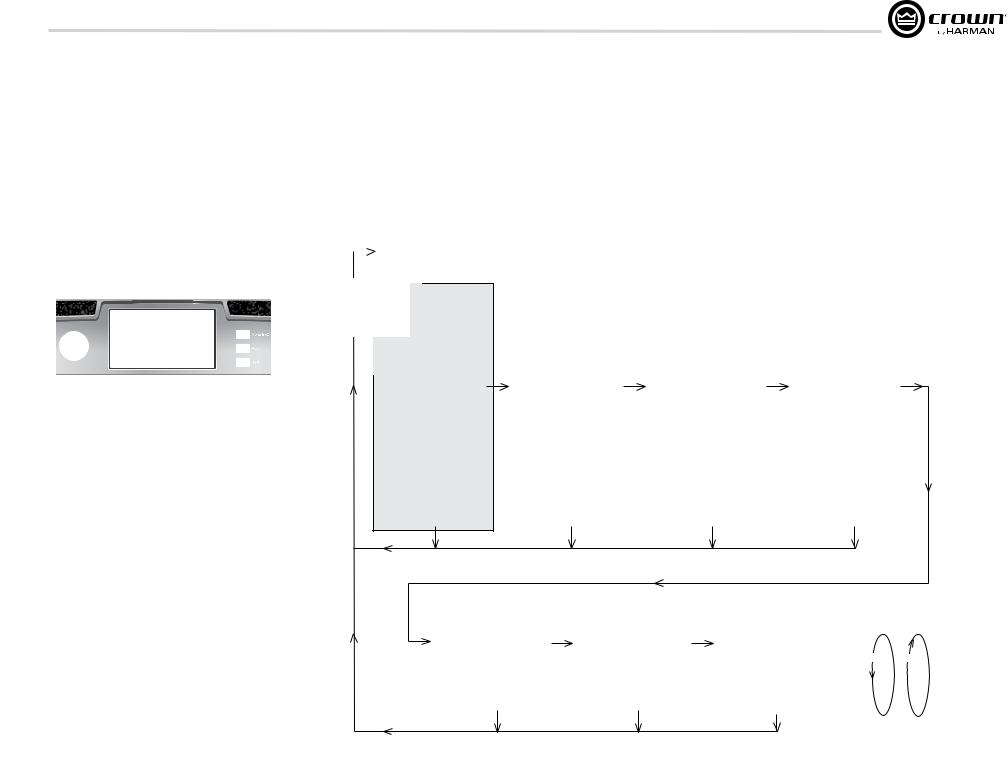
The LCD Control Screen and its controls let you configure the amplifier and access many features that before were available only through a remote computer. Also, you can recall DSP presets via the front panel. (Some DSP parameters cannot be adjusted with the LCD Control Screen. That is done in System Architect.)
Figure 7.1 shows the parts of the LCD Control Screen. Its functions are described below. NOTE: Listed functions can also be controlled in System Architect.
Here’s how to access the various menus and settings in the LCD control screen:
Menu/Exit
Figure 7.1 Parts of the LCD Control Screen
•Starting from the Attenuation screen, press Menu/Exit to go to the Menu screen.
•Press Next to go to the next item in the menu.
•Press Prev to go to the previous item in the menu.
•Turn or press the Encoder knob to change the value of a displayed parameter.
•When you see a menu screen, push the knob once to see the items in that menu. Or press Next to go to the next menu.
•Press Menu/Exit to leave the menu and return to the previous screen at any time.
Some menu items require confirmation: after you request a change, the display might say “Press and hold.” To confirm a change, press and hold the Encoder knob. If you don’t want the change to occur during a confirmation, turn the knob or wait five seconds.
The entire front panel or any selected screens can be locked out or set to read only status using System Architect software. Locked-out screens will either say “Lockout” or the individual parameter will say “N/A”. If a change is attempted the screen will say “Changes
Disabled”.
Touch Screen Functions
To Navigate: |
|
Shortcuts: |
Method 1 |
Method 2 |
• From the default display view, press and hold the |
• Press Menu/Exit button to enter menu screen |
• Press menu/exit button to enter menu screen |
encoder wheel (with no channels selected) to mute |
• Use previous & next buttons to cycle through |
• Press and drag with one finger to scroll through |
or unmute all channelss |
menus |
menus |
• From any menu, press and hold the menu exit |
• Click with encoder wheel to select menu |
• Tap with a finger on the menu to select |
button to return to the default display view |
MENU TREE
Attenuation - Mute - Lockout
 Menu Button
PRESETS
Menu Tree
As a handy reference, Figure 7.2 shows the menu structure of the LCD control screen. Starting from any Menu screen, press an Encoder knob to go to the first selection in the Menu. You can loop through a menu’s selections using the Next and Prev buttons. The Menu/Exit button returns you to the previous screen.
|
GENERAL PROPERTIES MENU |
|
ADVANCED MENU |
|
MONITOR MENU |
|
|
Sample Rate |
|
Attenuator Limits |
|
Global Metering |
|
|
Analog Input Sensitivity |
|
Attenuator Link |
|
Load Monitoring |
|
|
Amp Mode |
|
Input Source Priorities Ch 1 |
|
Thermal Percentage |
|
|
Locate |
|
Input Source Priorities Ch 2 |
|
Thermal Temperature |
|
|
Channel Labels |
|
Input Source Priorities Ch 3 |
|
AC Line Voltage |
|
Next |
Default Display View |
Next |
Input Source Priorities Ch 4 |
Next |
Operating Time |
Next |
Screen Configuration |
Maximum Analog Input |
Watts Output |
||||
|
LED Meter Display Type |
|
AES Input Trim |
|
|
|
|
Manufacturing Information |
|
AES Input Status |
|
|
|
|
|
|
Bandpass Gain |
|
|
|
|
|
|
Output Polarity |
|
|
|
|
|
|
Input Delay |
|
|
|
|
|
|
Driver Delay |
|
|
|
|
|
|
Clip Limiter |
|
|
|
|
|
|
Pink Noise Generator |
|
|
|
|
|
|
Sweep Load Monitoring |
|
|
|
|
|
|
LevelMax Suite Menu |
|
|
|
|
|
|
Limiter States |
|
|
|
|
|
|
Peak Voltage Limiter |
|
|
|
|
|
|
RMS Voltage Limiter |
|
|
|
|
|
|
Transducer Thermal Limiter |
|
|
|
|
|
|
|
|
|
|
Exit |
Exit |
Exit |
Exit |
|
ALERTS MENU |
|
NETWORK CONFIGURATION MENU |
|
COBRANET MENU |
ALL MENUS: |
|
Next |
Amp Output Clip Errors |
Next |
Network Information |
Next |
CobraNet Information |
Next/Previous loops |
|
|
|
||||||
|
Analog Input Clip Errors |
|
Manufacturing Information |
|
CobraNet Input Ch 1 |
|
|
|
Thermal Errors |
|
HiQnet Node Address |
|
CobraNet Input Ch 2 |
Next |
|
|
Low/High Limit Load Errors |
|
Network Settings |
|
CobraNet Input Ch 3 |
Prev |
|
|
Sweep Load Monitoring Errors |
|
|
|
CobraNet Input Ch 4 |
|
|
|
Line Voltage Errors |
|
|
|
CobraNet Foldback |
|
|
|
Fan Errors |
|
|
|
CobraNet Conductor Priority |
|
|
|
Clear All Error Logs |
|
|
|
CobraNet Transport Latency |
|
|
|
|
|
|
|
CobraNet Input Trim |
|
|
|
Exit |
|
Exit |
|
Exit |
|
|
Operation Manual |
Figure 7.2 The Menu Tree |
page 17 |
I-Tech HD DriveCore Series PowerAmplifiers
7 Advanced Operation
7.2 Operation Examples
Operation Example 1
How to set the CH1 input sensitivity using the LCD Control Screen:
1.After power-up, when the default display screen appears, press
Menu/Exit.
2.Press Next twice to reach the Advanced Menu, press the encoder wheel to select.
3.Press Next once to reach the Analog Input Sensitivity menu, then press the encoder wheel to select.
4.Tap on a channel and spin the encoder wheel to adjust the dB gain for that channel, press Menu/Exit to deselect.
5.When finished, press and hold the Menu/Exit button to return to the default display view.
Operation Example 2
How to monitor the Thermal Errors using the LCD Control Screen:
1.After power-up, when the default display screen appears, press
Menu/Exit.
2.Press Next four times to reach the Alerts Menu, press the encoder wheel to select.
3.Press Next two times to reach the Thermal Errors menu, then press the encoder wheel to select.
4.Tap on a channel to clear errors that channel, press Menu/Exit to deselect.
5.When finished, press and hold the Menu/Exit button to return to the default display view.
Now let’s look at the function of each menu selection.
7.2.1 Basic Selections
Opening Screen: On power-up, the LCD Control Screen displays the Crown logo. After a few seconds, the firmware version appears, then the Attenuation screen appears.
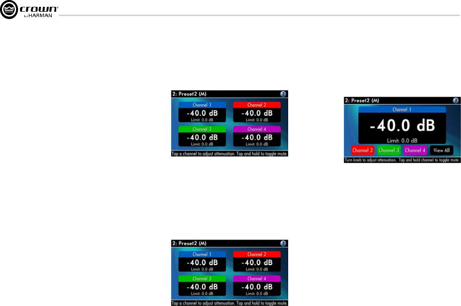
Attenuation and Bar Meters
This screen displays the attenuation in dB. To change attenuation tap a channel and turn the Encoder. Attenuation changes 0.5 dB per detent when you turn the Encoder slowly, and more when you turn the Encoder quickly. The current preset name is displayed in the upper-right corner. The (M) is explained on the next page under Presets.
If the attenuators for both channels are linked (in the Attenuator Link screen, described later), the word LINK appears. (If there is an error in the error log, an exclamation point appears at bottom center.)
Mute/Unmute (in the Attenuation screen)
•To mute a channel: The display will alternate between MUTE and the attenuation level. While the amplifier is muted, you can adjust attenuation for each channel by tapping to select and turning the Encoder knob.
•To unmute either channel: Press and hold for 1 second.
Front Panel Lockout (in the Attenuation screen)
The amplifier’s administrator can control access to menu mode and the amplifier’s attenuators. This lockout can be done either by the front panel buttons or by System Architect software.
To lock or unlock the menu with the front-panel buttons: press Next and Prev simultaneously. To lock or unlock the menu with System Architect software: go to the Tools Menu > Display Screen Security and press the lockout button. If a specific parameter is protected, the screen says “N/A” or “Change Disabled.”
If the lockout is done from the software, the user can disable the lockout only in the software, not by pressing the front-panel buttons.
If the menu is locked and you press any button or turn an Encoder, the word “LOCKOUT” is displayed. If a specific parameter is protected, the screen says “N/A” or “Change Disabled.”
page 18 |
Operation Manual |
I-Tech HD DriveCore Series PowerAmplifiers
7 Advanced Operation
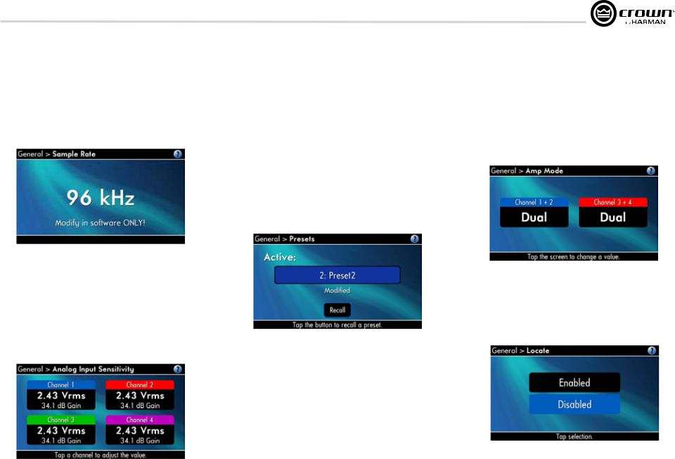
Sample Rate: Starting from the Attenuation screen, press Menu/Exit to go to the Sample Rate screen in the advanced mode. The sample rate of the amplifier’s DSP is displayed. It can be modified only in System Architect software because FIR filter settings will need to be recalculated as a result of the change. Please refer to its Help files. When you route a Cobranet input, the sample rate displayed here must match the Cobranet source.
Analog Input Sensitivity: (Tap to select a channel, turn the encoder to adj.) This screen also displays the amp gain for each channel resulting from the sensitivity settings.
Note: If you do not see the sensitivity you need, try changing the Maximum Analog Input level in the Advanced Menu (described later). This makes different sensitivities available.
To optimize the system gain structure, see Section 3.1 in the I-Tech application Guide at www.crownaudio.com/pdf/amps/137327.pdf.
Presets: A preset is a group of DSP and amplifier settings for a particular speaker system. Turn an Encoder to view Presets 1 through 50. To recall a preset, press the Encoder, then press and hold the Encoder to confirm. For more information on presets, see Section 7.3.
The preset currently in use is displayed in the upper right corner.
(A) Active means that the amplifier is operating exactly according to that preset.
(M) Modified means that the amplifier is operating according to the preset but with some settings changed.
If a preset number is flashing, it is not in use.
In the example shown below,
•Preset 2 is in use.
•The amplifier settings have been modified (M) since Preset 2 was loaded.
Amp Mode: This screen lets you set up the amplifier for Dual, Input Y or Bridge Mono mode. Turn an Encoder knob to choose among those three options, then press the knob to save your choice. You will be prompted to confirm your choice. The LCD screen displays the currently selected mode.
•In Dual (or Stereo) mode, both channels operate independently.
•In Bridge Mono mode, pairs of channels are summed to double the power, and the amplifier puts out a mono signal.
Locate: Allows users to identify a specific amplifier in a large network of amplifiers without having to compare address information. Locate can be turned on/off from software and/or the front panel. Press an Encoder knob to turn on the Locate function. When on, the LCD screen flashes. Press the knob again to turn off the Locate function. In System Architect, the device icon has a blue outline to indicate that it is in Locate mode.
Operation Manual |
page 19 |
I-Tech HD DriveCore Series PowerAmplifiers
7 Advanced Operation
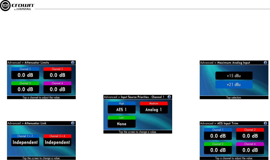
Attenuator Limits: You can set the maximum attenuation from 0 dB to –100 dB. This feature allows you to set a limit on the attenuators. Once set, attenuation cannot be adjusted beyond this level.
NOTE: The attenuator setting must be below the attenuator limit that you are trying to set. For example, if the attenuator is set at –3 dB, you cannot set the attenuator limit below –3 dB unless you decrease the attenuator level.
Attenuator Link You can set the attenudators to be independent or linked. Turn an Encoder knob to choose one of those options, then press the knob to save your choice.
Input Sources: For each channel, turn the Encoder to select analog, digital, or CobraNet Options are:
Analog
Digital
Digital with analog backup Digital with analog override
Digital with analog backup: The I-Tech HD is being fed a digital signal and an analog signal. The input is currently switched to the digital signal. If it fails, the I-Tech HD switches instantly to the analog signal.
Digital with analog override: The input is switched to the digital signal, and no analog signal is applied. If an analog signal is sent, the I-Tech HD switches instantly to the analog signal. If the analog signal fails, the I-Tech HD switches to the digital signal after a delay set by the Hold Time slider in the Input Section of the System Architect page.
Maximum Analog Input: Touch the screen to select: +21 dBu or +15 dBu. Note: Changing this value changes the range of sensitivities available to the amplifier.
For more information see Figure 7.3 and the I-Tech Sensitivity Charts in the Appendix of the I-Tech Application Guide. It is available online at www. crownaudio.com/pdf/amps/137327.pdf.
AES Input Trim: Turn the Encoder knob to vary the gain of the AES digital signal for Channel 1: -100.0 dB to +20 dB. See Figure 4.4 for more information.
page 20 |
Operation Manual |

I-Tech HD DriveCore Series PowerAmplifiers
7 Advanced Operation
AES Input Status: “Lock” indicates that an AES cable is plugged in and the amplifier is receiving (and locking to) the AES phase logs logs. “No Lock” means that the amplifier is not receiving, or is not locking to the AES
clock pulse.
CobraNet Input Trim: Turn the Encoder knob to vary the gain of the CobraNet digital signal for Channel 1: -100.0 dB to +20 dB. See Figure 4.4 for more information.
Bandpass Gain: In each channel of the I-Tech HD’s DSP, just before the output limiter and after the preceding filter, is a gain block (not shown on the Signal Path block diagram). Bandpass Gain adjusts the gain of this block between -24 dB and +24 dB.
Adjusting the bandpass gain in the LCD screen makes it easy to vary the level of subwoofers, midrange drivers and high-frequency drivers.
Output Polarity: Press each channel icon to toggle the output signal polarity between + and –.
Input Delay: Sets the input signal delay in each channel. Turn the Encoder knob to vary the delay. The delay step size is speed sensitive. Pressing the encoder enables or disables the Delay.
Below each channel’s delay setting is the equivalent distance in feet and meters. For example, 10 ms is the signal delay of sound traveling 11.3 feet or 3.4 m.
Output Delay: Sets the output signal delay in each channel. Turn the Encoder knob to vary the delay. The delay step size is speed sensitive. Pressing the encoder enables or disables the Delay.
Below each channel’s delay setting is the equivalent distance in feet and meters. For example, 10 ms is the signal delay of sound traveling 11.3 feet or 3.4 m.
Operation Manual |
page 21 |
I-Tech HD DriveCore Series PowerAmplifiers
7 Advanced Operation
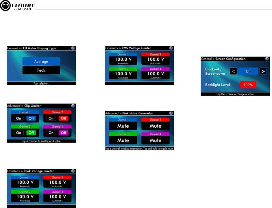
LED Meter Display Type : Here you can set the LCD bar meters to display average or peak levels. Turn the Encoder knob to select the option, then press the knob to confirm your selection.
LevelMax - RMS Voltage Limiter: Limits the output rms voltage to an amount that you set, either OFF or 1 to 500 volts, for each channel. Press the Encoder to turn on the Limiter. Once it’s on, turn the Encoder to set the voltage.
Front Panel Blackout: This screen lets you black out the front panel display unless you press a front-panel button or turn an Encoder. This feature turns off the LCD backlight and all front panel LEDs except for the fault LEDs and power-switch green LED. After blackout is enabled, an Encoder press/turn
will “reactivate” the display. If no button is pressed/turned for 5 seconds, the display will return to blackout mode.
LevelMax - Clip Limiter: Limits the peak output voltage to just below clipping for each channel. Press a channel icon to turn it OFF or ON.
Pink Noise Generator: Press a channel icon to turn on the generator. Its level will read –100 dB. Adjust the noise level from –100 dB to +20 dB in 0.5 dB steps by turning the Encoder. To turn off the generator, press and hold a channel icon or go to another menu item.
LevelMaxPeak Voltage Limiter: Limits the peak output voltage to a level that you set, either OFF or 1 to 500 volts, for each channel. Press an Encoder to turn on the Limiter. Once it’s on, turn the Encoder to set the voltage. Additional controls, such as attack and release, are available through System Architect.
page 22 |
Operation Manual |
 Loading...