


ComTech DriveCore Operation Manual
CT 475
CT 4150
CT 875
CT 8150
Obtaining Other Language Versions: To obtain information in another language about the use of this product, please contact your local Crown Distributor. If you need assistance locating your local distributor, please contact Crown at 574-294-8000.
This manual does not include all of the details of design, production, or variations of the equipment. Nor does it cover every possible situation which may arise during installation, operation or maintenance.
The information provided in this manual was deemed accurate as of the publication date. However, updates to this information may have occurred. To obtain the latest version of this manual, please visit the Crown website at www.crownaudio.com.
Trademark Notice: Com-Tech, BCA, Crown, Crown Audio, Amcron and Multi-Mode are registered trademarks of Crown International. IQwic, PIP and PIP2 are trademarks of Crown International. Other trademarks are the property of their respective owners.
Some models may be exported under the name Amcron®.
© 2011 by Harman International®, Inc. 1718 W. Mishawaka Rd., Elkhart, Indiana 46517-9439 U.S.A. Telephone: 574-294-8000
143368-2 6/11
CT Power Amplifiers
Important Safety Instructions Importantes Instructions de Sécurité
1.Read these instructions.
2.Keep these instructions.
3.Heed all warnings.
4.Follow all instructions.
5.Do not use this apparatus near water.
6.Clean only with a dry cloth.
7.Do not block any ventilation openings. Install in accordance with the manufacturer’s instructions.
8.Do not install near any heat sources such as radiators, heat registers, stoves, or other apparatus (including amplifiers) that produce heat.
9.Do not defeat the safety purpose of the polarized or grounding-type plug. A polarized plug has two blades with one wider than the other. A grounding-type plug has two blades and a third grounding prong. The wide blade or the third prong is provided for your safety. If the provided plug does not fit into your outlet, consult an electrician for replacement of the obsolete outlet.
10.Protect the power cord from being walked on or pinched, particularly at plugs, convenience receptacles, and the point where they exit from the apparatus.
11.Only use attachments/accessories specified by the manufac turer.
12. Use only with a cart, stand, tripod, bracket, or table specified by the manufacturer, or sold with the apparatus. When a cart is used, use caution when moving the cart/ apparatus combination to avoid injury from tip-over.
13.Unplug this apparatus during lightning storms or when unused for long periods of time.
14.Refer all servicing to qualified service personnel. Servicing is required when the apparatus has been damaged in any way, such as power-supply cord or plug is damaged, liquid has been spilled or objects have fallen into the apparatus, the apparatus has been exposed to rain or moisture, does not operate normally, or has been dropped.
15.Use the mains plug to disconnect the apparatus from the mains.
16.WARNING: TO REDUCE THE RISK OF FIRE OR ELECTRIC SHOCK, DO NOT EXPOSE THIS APPARATUS TO RAIN OR MOISTURE.
17.DO NOT EXPOSE THIS EQUIPMENT TO DRIPPING OR
SPASHING AND ENSURE THAT NO OBJECTS FILLED
WITH LIQUIDS, SUCH AS VASES, ARE PLACED ON THE
EQUIPMENT.
18.THE MAINS PLUG OF THE POWER SUPPLY CORD SHALL REMAIN READILY OPERABLE.
Wichtige Sicherheitsinstruktionen
Instrucciones de Seguridad Importantes
TO PREVENT ELECTRIC SHOCK DO NOT REMOVE TOP OR
BOTTOM COVERS. NO USER SERVICEABLE PARTS INSIDE.
REFER SERVICING TO QUALIFIED SERVICE PERSONNEL.
ÀPRÉVENIR LE CHOC ÉLECTRIQUE N’ENLEVEZ PAS LES COUVERCLES. IL N’Y A PAS DES PARTIES SERVICEABLE
ÀL’INTÉRIEUR. TOUS REPARATIONS DOIT ETRE FAIRE PAR PERSONNEL QUALIFIÉ SEULMENT.
PARA PREVENIR UN CHOQUE ELÉCTRICO, NO RETIRE LAS
CUBIERTAS SUPERIOR O INFERIOR. NO EXISTEN PARTES QUE
PUEDAN SER REPARADAS POR EL USUARIO AL INTERIOR.
REMITA EL SERVICICO AL PERSONAL TÉCHNICAL CALIFI-
CADO.
TO COMPLETELY DISCONNECT THIS EQUIPMENT FROM THE
AC MAINS, DISCONNECT THE POWER SUPPLY CORD PLUG
FROM THE AC RECEPTACLE. THE MAINS PLUG OF THE POWER
SUPPLY CORD SHALL REMAIN READILY OPERABLE.
IMPORTANT
CT Series amplifiers require Class 2 output wiring.
Les amplificateurs de série de CT exigent des câbles de sortie de classe 2.
CT-Reihe-Verstärker verlangen Klasse die 2 Produktionsverdrahtung. Los amplificadores de la Serie CT requieren de un cableado de salida Clase 2.
MAGNETIC FIELD
CAUTION! Do not locate sensitive high-gain equipment such as preamplifiers directly above or below the unit. Because this amplifier has a high power density, it has a strong magnetic field which can induce hum into unshielded devices that are located nearby. The field is strongest just above and below the unit.
If an equipment rack is used, we recommend locating the amplifier(s) in the bottom of the rack and the preamplifier or other sensitive equipment at the top.
POUR DÉMONTER COMPLÈTEMENT L’ÉQUIPEMENT DE L’ALIMENTATION GÉNÉRALE, DÉMONTER LE CÂBLE D’ALI MENTATION DE SON RÉCEPTACLE. LA PRISE D’ALIMENTATION RESTERA AISÉMENT FONCTIONNELLE.
PARA DESCONECTAR COMPLETAMENTE EL EQUIPO DEL SUMINSTRO ELECTRICO, DESCONECTE EL CABLE DE ALI MENTACION DE LA TOMA DE CA. LAS PATAS DEL CONECTOR DEL CABLE DE ALIMENTACIÓN DEBERAN MANTENERSE EN BUEN ESTADO.
WATCH FOR THESE SYMBOLS:
The lightning bolt triangle is used to alert the user to the risk of electric shock.
The exclamation point triangle is used to alert the user to important operating or maintenance instructions.
REGARDEZ CES SYMBOLES:
La triangle avec le sigle ‘’foudre’’ est employée pour alerter l’utilisateur au risque de décharge électrique. Le triangle avec un point d’exclamation est employée pour alerter l’utilisateur d’instruction importantes pour lors opérations de maintenance.
ATENCION CON ESTOS SÍMBOLOS:
El triángulo con el símbolo de rayo eléctrico es usado para alertar al usuario de el riesgo de un choque eléctrico.
El triángulo con el signo de admiración es usado para alertar al usuario de instrucciones importantes de operación o man tenimiento.
FCC COMPLIANCE NOTICE
This device complies with part 15 of the FCC rules. Operation is subject to the following two conditions: (1) This device may not cause harmful interference, and (2) this device must accept any interference received, including interference that may cause undesired operation.
CAUTION: Changes or modifications not expressly approved by the party responsible for complicance could void the user’s authority to operate the euqipment.
NOTE: This equipment has been tested and found to comply with the limits for a Class B digital device, pursuant to part 15 of the FCC Rules. These limits are designed to provide reasonable protection against harmful interference in a residential installation. This equipment generates, uses, and can radiate radio frequency energy and, if not installed and used in accordance with the instruction manual, may cause harmful interference to radio communications. However, there is no guarantee that interference will not occur in a particular installation. If this equipment does cause harmful interference to radio or television reception, which can be determined by turning the equipment off and on, the user is encouraged to try to correct the interference by one or more of the following measures:
•Reorient or relocate the receiving antenna.
•Increase the separation between the equipment and receiver.
•Connect the equipment into an outlet on a circuit different from that to which the receiver is connected.
•Consult the dealer or an experienced radio/TV technician for help.
page 2 |
Operation Manual |
CT Power Amplifiers
DECLARATION of CONFORMITY
ISSUED BY: Harman International
1718 W. Mishawaka Road
Elkhart, Indiana 46517 U.S.A.
European Representative’s Name and Address:
David Budge
10 Harvest Close
Yateley GU46 6YS
United Kingdom
Equipment Type: Power Amplifiers
Family Name: CT series
Model Names: CT8150, CT875, CT4150, CT475
EMC Standards:
EN 55103-1:1997 Electromagnetic Compatibility – Product Family Standard for Audio, Video, Audio-Visual and Entertainment Lighting Control Apparatus for Professional Use, Part 1: Emissions EN 55103-1:1997 Magnetic Field Emissions-Annex A @ 10 cm and 1 M
EN 61000-3-2:2006 & Amd 1: 2008 & AMd 2 : 2009 Limits for Harmonic Current Emissions (equipment input current ≤16A per phase) EN 61000-3-3:1998 Limitation of Voltage Fluctuations and Flicker in Low-Voltage Supply Systems Rated Current ≤16A
EN 55022:2006 Limits and Methods of Measurement of Radio Disturbance Characteristics of ITE: Radiated, Class B Limits; Conducted, Class B
EN 55103-2:1997 Electromagnetic Compatibility – Product Family Standard for Audio, Video, Audio-Visual and Entertainment Lighting Control Apparatus for Professional Use, Part 2: Immunity EN 61000-4-2:2009 Electrostatic Discharge Immunity (Environment E2-Criteria B, 4k V Contact, 8k V Air Discharge)
EN 61000-4-3:2006 Radiated, Radio-Frequency, Electromagnetic Immunity (Environment E2, Criteria A) EN 61000-4-4:2007 Electrical Fast Transient/Burst Immunity (Criteria B)
EN 61000-4-5:2006 Surge Immunity (Criteria B)
EN 61000-4-6:2009 Immunity to Conducted Disturbances Induced by Radio-Frequency Fields (Criteria A) EN 61000-4-11:2001 Voltage Dips, Short Interruptions and Voltage Variation
Safety Standard:
IEC 60065: 2001: 7Ed & Amd 1: 2005 Safety Requirements - Audio Video and Similar Electronic Apparatus
I certify that the product identified above conforms to the requirements of the EMC Council Directive 2004/108/EC and the Low Voltage Directive 2006/95/EC.
Signed
Scott Potosky
Title: Director of Engineering
Date of Issue: March 16, 2011
Operation Manual |
Due to line current harmonics, we recommend that you contact your supply authority before connection. |
page 3 |
CT Power Amplifiers
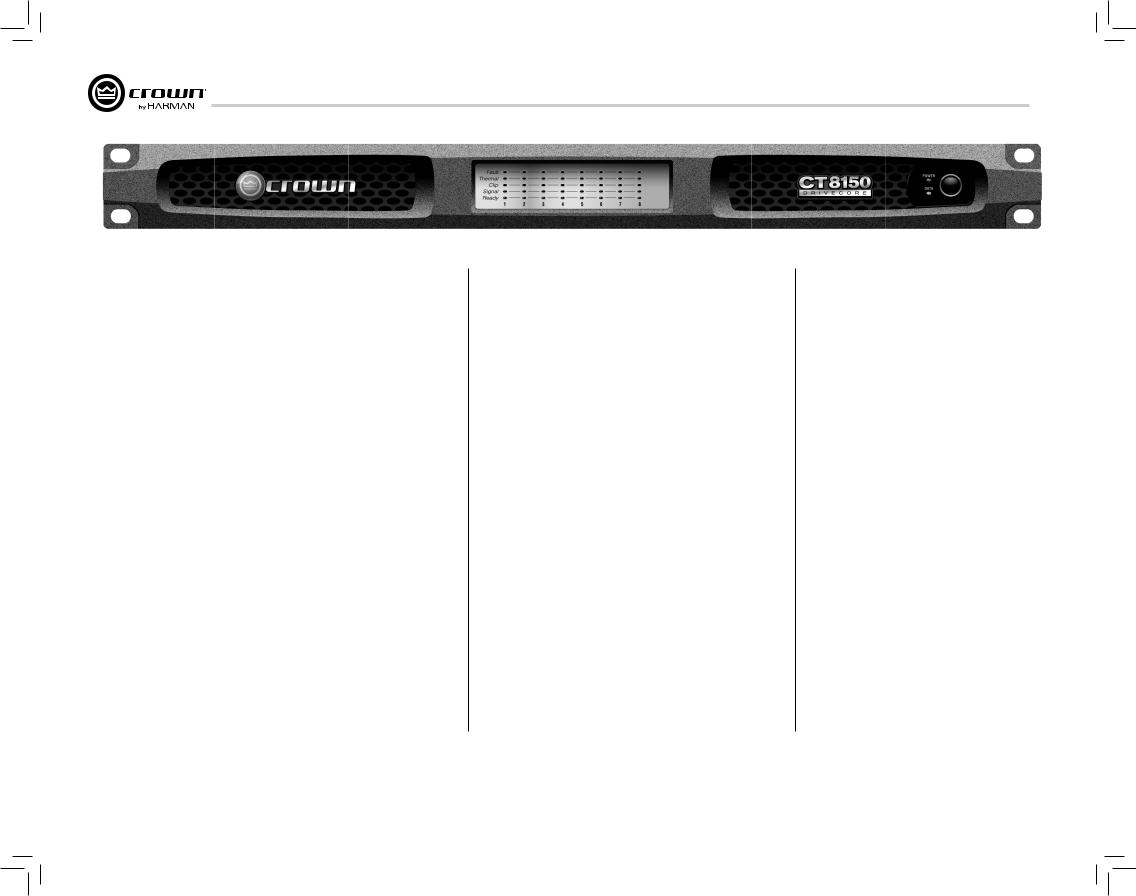
1 Welcome
Crown® ComTech DriveCore™ amplifiers provide state-of-the-art technology for installed sound applications. The ComTech amplifiers provide noiseless operation and small footprint with excellent quality and performance.
ComTech DriveCore amplifiers offer:
1.1 Features
Audiophile Sound
•A signal-to-noise ratio of better than 110dB
•Total harmonic distortion below 0.05% across the full audio bandwidth
•Greater than 70dB crosstalk
•Frequency response of ±0.5dB
Size Advantage
•Up to 8 channels in a single rack-space
•Weight of only 10 pounds (4.54 Kg)
Power Efficiency
•Over 90% efficient in the DriveCore amplifier stage
•Power consumption of less than 1W when not in use (In Deep Sleep)
•Green Mode delivers power when needed. Amplifier efficency increases by up to 10% when compared to typical class D amplifiers
Typical applications for ComTech DriveCore amplifiers include boardrooms, video and teleconferencing, VIP suites in stadiums and arenas, and upscale restaurants and retail outlets.
2 How to Use This Manual
This manual provides you with the necessary information to safely and correctly set up and operate your amplifier. It does not cover every aspect of installation, setup, or operation that might occur under every condition. For additional information, please consult Crown’s Amplifier Application Guide (available online at www. crownaudio.com), Crown Technical Support, your system installer, or system retailer).
3 Features
•4 channel or 8 channel (4 inputs with 4 outputs or 8 inputs with 8 outputs)
•Single rack space
•Balanced 3-pin Barrier block-type/line inputs
•4-pin Phoenix-type speaker outputs
•Flexible input routing
•Multiple Power Configuration (Auto-Standby, Deep Sleep, and Green Mode)
•Auxiliary port for amp status and power saving mode (Deep Sleep)
•Circuit breaker protection with reset switch
•Convection-cooled chassis (no fan)
•Three-year, no-fault, fully transferable warranty that completely protects your investment and guarantees its specifications
•Can be used in mass notification and EN 54 systems
•Patented technology including DriveCoreTM
•Fault Reporting through Aux Port
•Adaptive Rail Technology for power on demand.
•Complies with Green Edge by Harman
page 4 |
Operation Manual |
CT Power Amplifiers
4 Setup
4.1 UnpackYour Amplifier |
4.2 InstallYour Amplifier |
4.3 Ensure Proper Cooling |
Please unpack and inspect your amplifier for any damage that may have occurred during transit. If damage is found, notify the transportation company immediately. Only you can initiate a claim for shipping damage. Crown will be happy to help as needed. Save the shipping carton as evidence of damage for the shipper’s inspection.
We also recommend that you save all packing materials so you will have them if you ever need to transport the unit. Never ship the unit without the factory pack.
YOU WILL NEED (not supplied):
•Input wiring cables
•Output wiring cables
•Flathead screwdriver
Rack for mounting amplifier (or a stable surface for stacking)
WARNING: Before you start to set up your amplifier, make sure you read and observe the Important Safety Instructions found at the beginning of this manual.
CAUTION: Before you begin, make sure your amplifier is disconnected from the power source and that all level controls (see section 7.6) are set to 0.
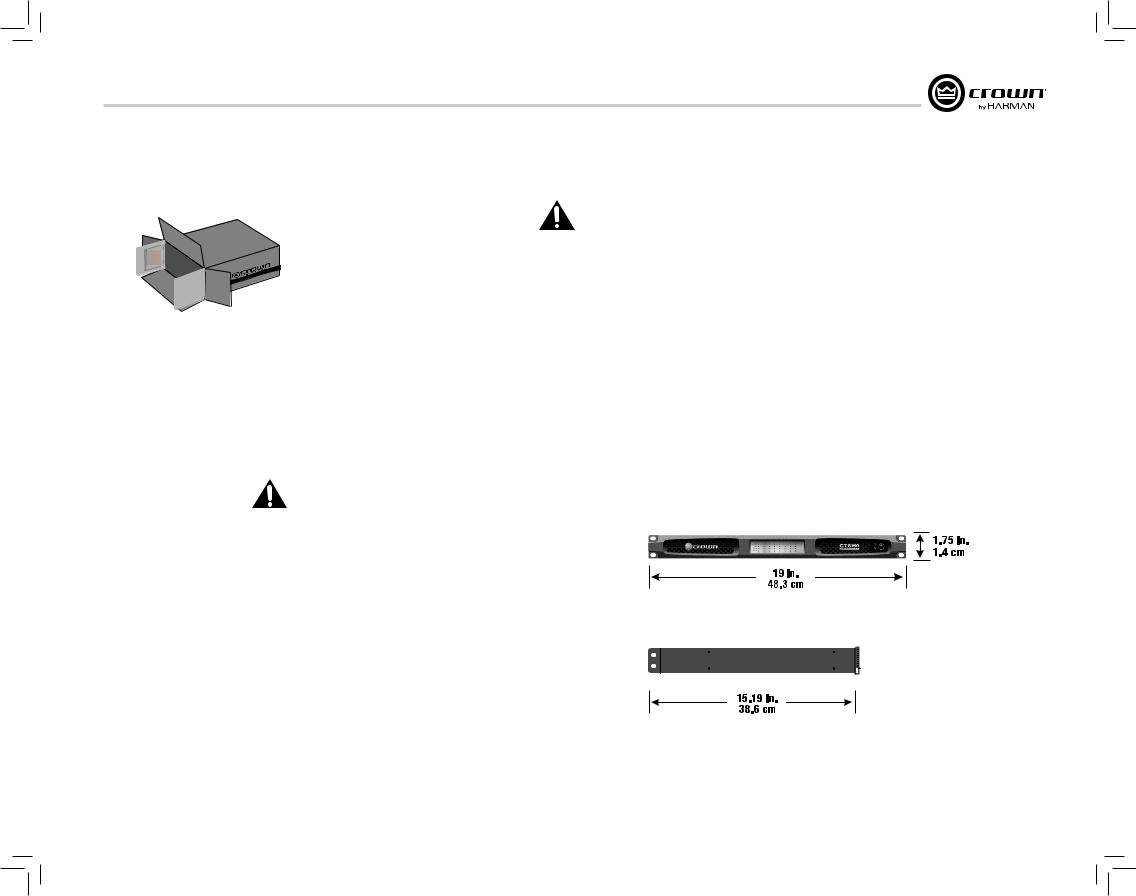
The amplifier is 1.75” tall by 15.19” deep and 19” wide (see figure 4.2.1).
Mount the unit in a standard 19-inch (48.3-cm) equipment rack (EIA RS-310B). You can also place a single amp on a solid, stable surface or stack multiple amps.
NOTE: When transporting, amplifiers should be supported at both front and back.
When using an equipment rack, mount units directly on top of each other. Close any open spaces in the rack with blank panels. DO NOT block front, top or side air vents.
The side walls of the rack should be a minimum of two inches (5.1 cm) away from the amplifier sides, and the back of the rack should be a minimum of four inches (10.2 cm) from the amplifier back panel. While the amplifier is convection cooled and does not require a fan, it is critical that the air vents are not covered.
Figure 4.2.1 CT Series Dimensions
Operation Manual |
page 5 |
CT Power Amplifiers
4 Setup
4.4 Choose Input Wire |
4.5 Choose Output Wire and |
and Connectors |
Connectors |
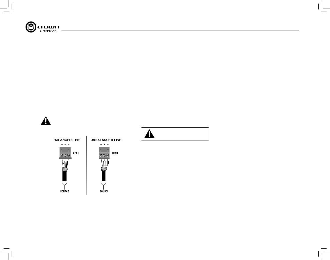
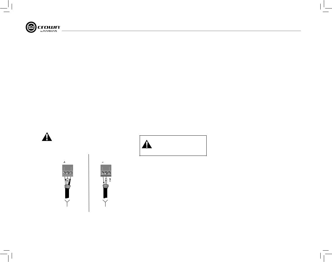
Crown recommends using pre-built or professionally wired balanced line (twoconductor plus shield). Balanced wiring provides better rejection of unwanted noise and hum but unbalanced line may also be used. For more information, refer to the Crown Amplifier Application Guide, available online at www. crownaudio.com.
Use 3-pin Phoenix-type cable ends at the amp input connectors.
Figure 4.4.1 shows connector pin assignments for balanced wiring and figure 4.4.2 shows connector pin assignments for unbalanced wiring.
NOTE: Custom wiring should only be performed by qualified personnel. Class 2 wiring is required.
Crown recommends using professionally constructed, high quality, two-conductor, heavy gauge speaker wire and connectors. Use 2-pin Phoenix-type connectors (Included with the amp).
Suggested below are guidelines to select the appropriate size of wire based on the distance from amplifier to speaker. Check with local code as this may vary.
Distance |
Wire Size |
up to 25 ft. (7.6m) |
16 AWG |
26-40 ft. (7.9-12.2m) |
14 AWG |
CAUTION: Never use shielded cable for output wiring.
CAUTION: Never connect the speaker return to the chassis of the amplifier, or damage to the amplifier may result.
CAUTION: Output of amplifier channels cannot be bridged. This may damage the amplifier.
Figure 4.4.1 |
Figure 4.4.2 |
page 6 |
Operation Manual |
CT Power Amplifiers
4 Setup
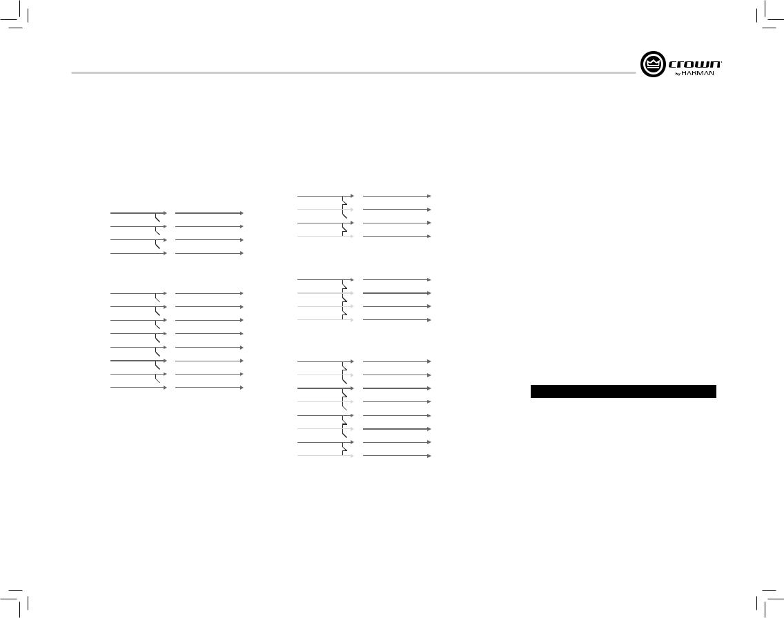
4.6 WireYour System
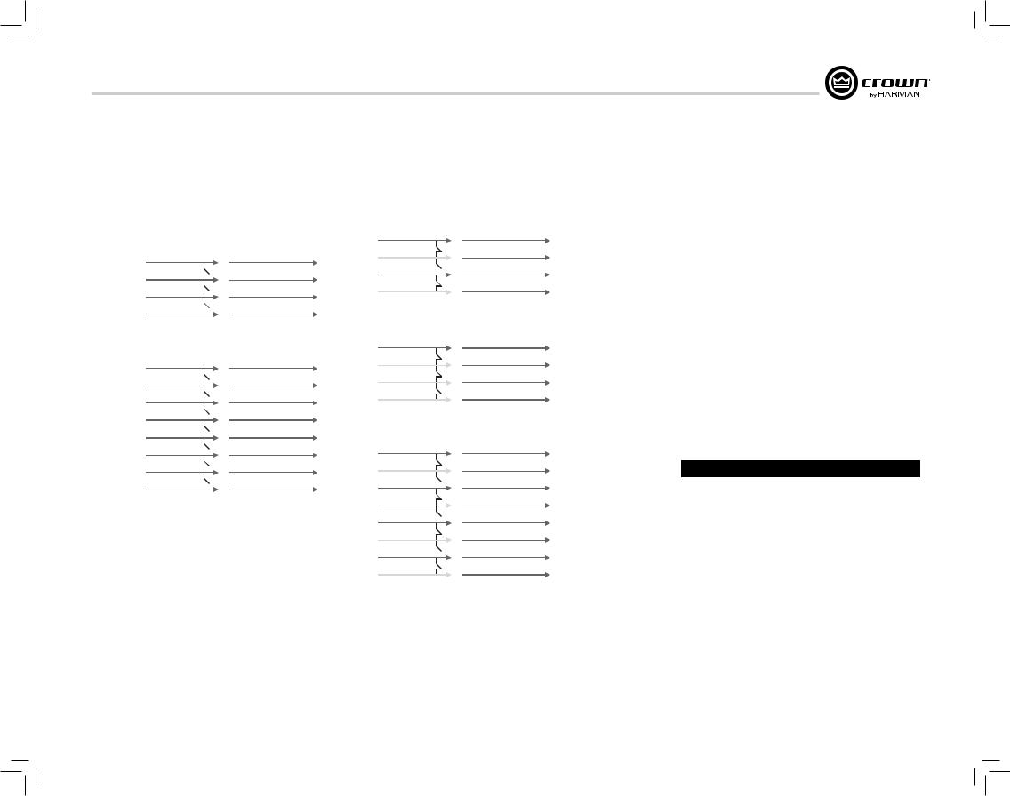
Before you wire your system, you must be familiar with the capabilities of the input routing.
The DriveCore amplifier can be configured in two ways:
1. The input for a channel goes out the same channel. This option is the standard configuration.
CHANNEL 1 |
RIVED |
CHANNEL 1 |
||
|
|
|
|
|
CHANNEL 2 |
|
|
OREC |
CHANNEL 2 |
|
||||
|
|
|
|
|
CHANNEL 3 |
|
|
MPLIFIERA |
CHANNEL 3 |
|
||||
CHANNEL 4 |
|
|
CHANNEL 4 |
|
|
|
|
||
|
|
|
|
|
Figure 4.6.1 Four channels with no input routing
CHANNEL 1 |
RIVED |
CHANNEL 1 |
||
|
|
|
|
|
CHANNEL 2 |
|
|
OREC |
CHANNEL 2 |
|
||||
|
|
|
|
|
CHANNEL 3 |
|
|
MPLIFIERA |
CHANNEL 3 |
|
||||
CHANNEL 4 |
|
|
CHANNEL 4 |
|
|
|
|
||
CHANNEL 5 |
|
|
|
CHANNEL 5 |
|
|
|||
CHANNEL 6 |
|
|
|
CHANNEL 6 |
|
|
|||
CHANNEL 7 |
|
|
|
CHANNEL 7 |
|
|
|||
CHANNEL 8 |
|
|
|
CHANNEL 8 |
|
|
|||
|
|
|
|
|
Figure 4.6.2 Eight channels with no input routing
Operation Manual
2. The input for a channel can be routed to the next channel, overriding the wired input signal for that channel. This method simplifies input wiring and minimizes use of y-cables.
CHANNEL 1 |
RIVED |
CHANNEL 1 |
|||
CHANNEL 2 |
CHANNEL 2 |
||||
OREC |
|||||
|
|
|
|
||
CHANNEL 3 |
|
|
MPLIFIERA |
CHANNEL 3 |
|
|
|||||
CHANNEL 4 |
CHANNEL 4 |
||||
|
|||||
|
|
|
|
|
|
Figure 4.6.3 Two channel to four channel routing
CHANNEL 1 |
RIVED |
CHANNEL 1 |
|
CHANNEL 2 |
CHANNEL 2 |
||
OREC |
|||
|
|
||
CHANNEL 3 |
MPLIFIERA |
CHANNEL 3 |
|
CHANNEL 4 |
CHANNEL 4 |
||
|
|||
|
|
|
Figure 4.6.4 One channel to four channel routing
CHANNEL 1 |
RIVED |
CHANNEL 1 |
|||
CHANNEL 2 |
CHANNEL 2 |
||||
OREC |
|||||
|
|
|
|
||
CHANNEL 3 |
|
|
A |
CHANNEL 3 |
|
|
|
MPLIFIER |
|||
CHANNEL 4 |
CHANNEL 4 |
||||
|
|||||
CHANNEL 5 |
|
|
|
CHANNEL 5 |
|
|
|
||||
CHANNEL 6 |
|
CHANNEL 6 |
|||
CHANNEL 7 |
|
|
|
CHANNEL 7 |
|
|
|
||||
CHANNEL 8 |
|
CHANNEL 8 |
|||
|
|
|
|
|
|
Figure 4.6.5 Four channel to eight channel routing
Input routing is configured using the dip switches on the back of the amplifier. See Section 11 Input Routing for information on configuring switches.
Note: ComTech DriveCore amplifiers can NOT be bridged.
4.7 Connect to AC Mains
Connect your amplifier to the AC mains power source (power outlet) with the supplied AC power cordset. First, connect the IEC end of the cordset to the IEC connector on the amplifier; then, plug the other end of the cord set to the AC mains.
WARNING: The third prong of this connector (ground) is an important safety feature. Do not attempt to disable this ground connection by using an adapter or other methods.
Amplifiers don’t create energy. The AC mains voltage and current must be sufficient to deliver the power you expect. If the AC line voltage varies out of an acceptable range, the amplifier’s power supply turns off and the blue Power LED flashes. The amplifier will turn back on when the AC line voltage returns to safe operating levels.
Figure 4.7.1 provides voltage limits for all amplifier AC voltage configurations. Also, the amplifier must be run within the specified mains frequency requirements (indicated on the amplifier’s back panel label). If you are unsure of the output voltage of your AC mains, please consult your electrician.
Model |
Under-Voltage Limit |
Over-Voltage Limit |
|
|
|
All Models |
90 VAC |
264 VAC |
|
|
|
Figure 4.7.1 AC Under-Voltage and Over-Voltage Limits for Various Amplifier Models
page 7

CT Power Amplifiers
4 Setup
4.8 Startup Procedure
Use the following procedure when first turning on your amplifier:
1.Turn down the level of your audio source.
2.Turn down the level controls of the amplifier (see Section 7.6).
3.Turn on the “Power” switch. The Power indicator should glow.
4.Turn up the level of your audio source to an optimum level.
5.Turn up the Level controls on the amplifier until the desired loudness or power level is achieved.
If you ever need to make any wiring or installation changes, don’t forget to turn off the amplifier and disconnect the power cord.
For help with determining your system’s optimum gain structure (signal levels) please refer to the Crown
Amplifier Application Guide, available online at www.crownaudio.com.
5 Precautions
Your amplifier is protected from internal and external faults, but you should still take the following precautions for optimum performance and safety:
1.Before use, your amplifier first must be configured for proper operation, including input and output wiring hookup. Improper wiring can result in serious operating difficulties. For information on wiring and configuration, please consult the Setup section of this manual or, for advanced setup techniques, consult Crown’s Amplifier Application Guide available online at www.crownaudio.com.
2.Use care when making connections, selecting signal sources and controlling the output level. The load you save may be your own!
3.Do not short the ground lead of an output cable to the input signal ground. This may form a ground loop and cause oscillations.
4.Never connect the output to a power supply, battery or power main. Electrical shock may result.
5.Tampering with the circuitry, or making unauthorized circuit changes may be hazardous and invalidates all agency listings.
6.Do not operate the amplifier with the red Clip LEDs constantly flashing.
7.Do not overdrive the mixer, which will cause clipped signal to be sent to the amplifier. Such signals will be reproduced with extreme accuracy, and loudspeaker damage may result.
8.Do not operate the amplifier with less than the rated load impedance. Due to the amplifier’s output protection, such a configuration may result in premature clipping and speaker damage.
9.Output of amplifier cannot be bridged or multiple channels cannot be connected together.
Remember: Crown is not liable for damage that results from overdriving other system components.
page 8 |
Operation Manual |
CT Power Amplifiers
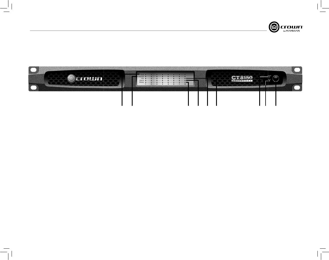
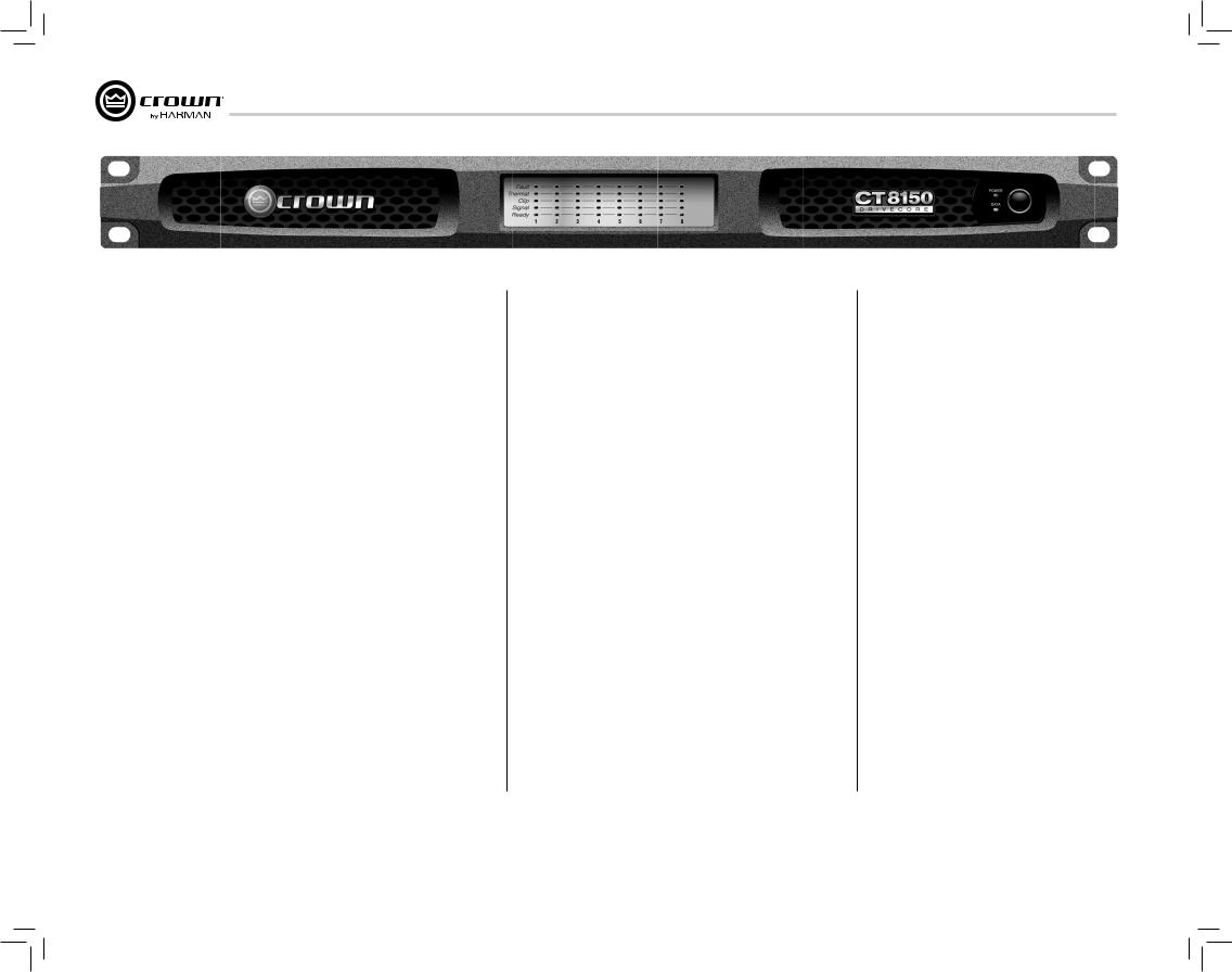
6 Front Panel
1 |
2 |
5 |
4 |
3 |
9 |
1.Fault Indicator
•Red LED
•One per output channel
•Flashes when the amplifier output channel has stopped operating. Usually this means that the amplifier must be serviced. (See Section 15 Troubleshooting)
2.Thermal Indicator
•Red LED
•One per output channel
•If exceeds Thermal Limits, output channels will shut down in pairs until thermal levels are within tolerant ranges.
•Illuminates when the channel approaches temperature constraints or is about to shut down. Audible distortion may be heard.
•Unit stops amplification for each channel until temperature returns to acceptable level. Once the amp cools off enough, led turns off, audio starts again.
3.Clip Indicator
•Red LED
•One per output channel
•Illuminates when the channel is at the threshold of audible distortion (See Section 15 Troubleshooting – reduce input level)
•When the limiter is turned on the Clip
Indicator will illuminate when the limiter is protecting the amplifier from input overload.
4.Signal Indicator
•Green LED
•One per input channel
•Illuminates when the input signal exceeds -24dBu
5.Ready Indicator
•Green LED
•One per input channel
•Illuminates when the channel is ready for signal
•Illuminates when the channel is initialized and ready to produce audio output.
•Ready indicator will flash when the channel is in standby.
•Ready Indictor will not illuminate or flash when the amplifier is in deep sleep.
6.Power Indicator
•Blue LED
•Indicates AC power has been applied and is within the safe operating range of the power supply. The LED will flash when the AC line voltage is above or below the nominal rated value. The LED will also flash when the amplifier is in Deep Sleep mode AND the power button has been pushed.
6 7 8
7.Data Indicator
•Yellow LED (not functional in analog version)
•Indicates network activity
•Reserved for future releases
(Lite and DSP)
8.Power Button
•On/off push button
9.Cooling Vent
•Allows for air flow and cooling of the amplifier
Operation Manual |
page 9 |
CT Power Amplifiers
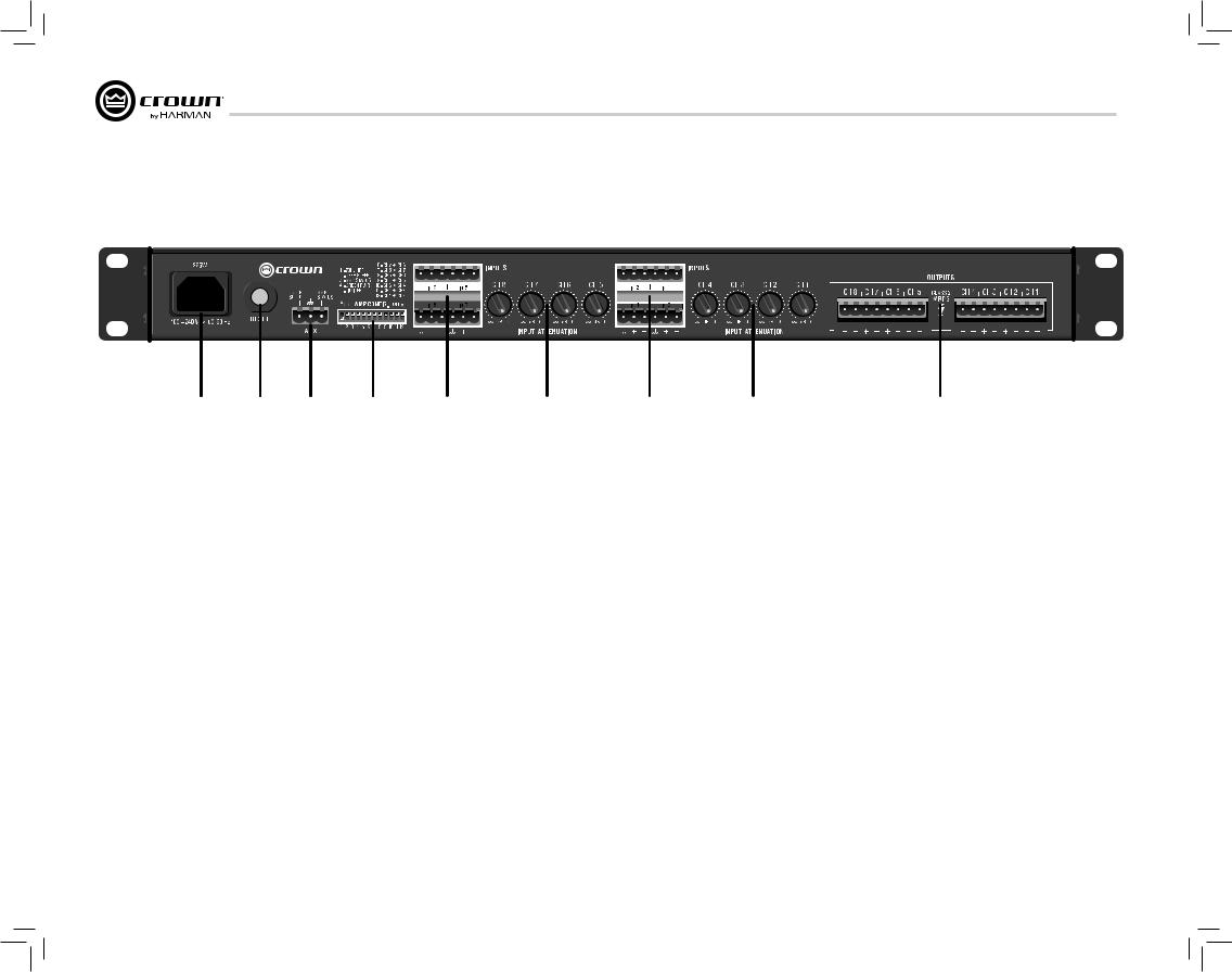
7 Back Panel
|
|
|
|
|
|
|
|
|
|
|
|
|
|
|
|
|
|
|
|
|
|
|
|
|
|
|
|
|
|
|
|
1 |
2 |
3 |
4 |
5 |
|||
1.AC Power Inlet
•Standard IEC type 320 inlet for detachable connector
•100-240V
2.Reset Button/Breaker
•Push button switch
•Resets the circuit breaker that protects the power supply
•A circuit breaker located near the IEC power inlet protects the amplifier from excessive AC current draw.
3.Auxiliary Connector
•3-pin Phoenix type connector
•Allows for amp to be placed in DEEP SLEEP mode and monitoring of AMP STATUS (see Section 10.2)
|
|
|
|
|
|
|
|
|
|
|
|
|
|
|
6 |
5 |
6 |
4.Amp Configuration DIP Switches (see Amp Status/Configuration in section 10.2)
•Switches 1-5 turn specific settings on and off:
-70 Hz HPF (High Pass Filter - see Section 8.1)
-Auto-Standby -Amp Status
-Green Power (See Section 9.2) -Limiter
•Switches 6-12 sends input channel audio signal to corresponding output channel and adjacent output channel. In four channel model, switch 6-9 are non-functional, (see section 11)
7
5.Amp Input Connectors
•3-pin block connector can be used per input
•High impedance balanced
6.Channel Level Controls
•One 21-position detented rotary attenuator per channel
•Attenuation range from -100dB to 0dB
7.Output Speaker Connector
•4-pin Barrier block type per two channels
(2-Pin or 8-Pin Phoenix can be used)
page 10 |
Operation Manual |
CT Power Amplifiers
8 Amp Configuration
8.1 70Hz HPF (High Pass Filter)
On the back panel, one 2-position high-pass filter switch will only allow signals above 70Hz to be amplified. This is to prevent transformer saturation. The HPF, when turned on, is activated for all channels. The filter is a 2nd order 12 dB/occ t filter.
8.2 Limiter
The limiter reduces amplifier gain to allow over drive without harsh clipping at output.
When Amp Configuration Switch #5 is set to on (pushed up), the amplifier will utilize the limiter feature.
9 Operating Modes
DriveCore Amplifiers can work in a variety of power modes.
9.1 Normal
The amplifier automaticaly operates full output power.
9.2 Green Power
Green mode utilizes Crown’s adaptive rail technology for higher efficiency or power on demand. When Amp Configuration DIP switch #4 is set to on, the amplifier will operate in green mode.
For low input signal levels (less than –40dBu) the amplifier will operate with minimum power.
The amplifier will increase to full power if either of the following occurs:
1 - The input signal goes above -40dBu
2 - There is a single clip event from any of the channels
Likewise, if the amplifier is operating with full power, the amplifier will decrease the operating rails to minimum power if the input signal drops
below -40dBu.
Through the use of Green Power, the efficiency of the amplifier dramatically increases for lower audio signal reproduction. The adaptive rail technology used in the CT amplifiers can increase the efficiency of the amplifier by up to 10% with low signal levels.
9.3 Deep Sleep
See Section 10.1
Is green mode |
NO |
Full Power |
|
DIP switch on? |
|||
|
|
Y
E
S
Lower voltage rails
Is there a clip |
NO |
Minimum Power |
|
event? |
|||
|
|
Y
E
S
Increase rails to Full Power
Figure 9.2.1 How Green Power DIP switches work
Operation Manual |
page 11 |
10 Auxiliary Port
10.1 Deep Sleep
In deep sleep mode, the amp consumes less than 1 watt of power. It is activated via the AUX port with a ground closure.
To bring the amplifier out of deep sleep, remove the ground closure via the AUX port.
10.2 Amp Status
The Amplifier Status is designed to work with life safety or supervisory monitoring and control systems, where notification of an amplifier fault is necessary. The Amplifier Status is producing a signal (Heartbeat or tone) when the amplifier is operating within standard working parameters. If the amplifier enters a fault or thermal condition, the Amplifier Status signal will terminate. This feature in the ComTech amplifier is always on. The Amplifier Status is located on the Auxiliary Port, opposite the DEEP SLEEP function. The configuration of the Amp Status signal is possible through DIP Switch #3:
•ON – the microcontroller will send a 1 Hz pulse to the “AMP STATUS” AUX port line
•OFF – the microcontroller will send a logic high level to the “AMP STATUS” AUX port line
The voltage output of the AuxPort is 5VDC at 50 milliamps. This TTL or similar signal can then be connected to an interface to indicate the status to a supervisory control system.
Amp status can be used in a variety of life safety applications, such as EN54, IEC60849 among others.
page 12
CT Power Amplifiers
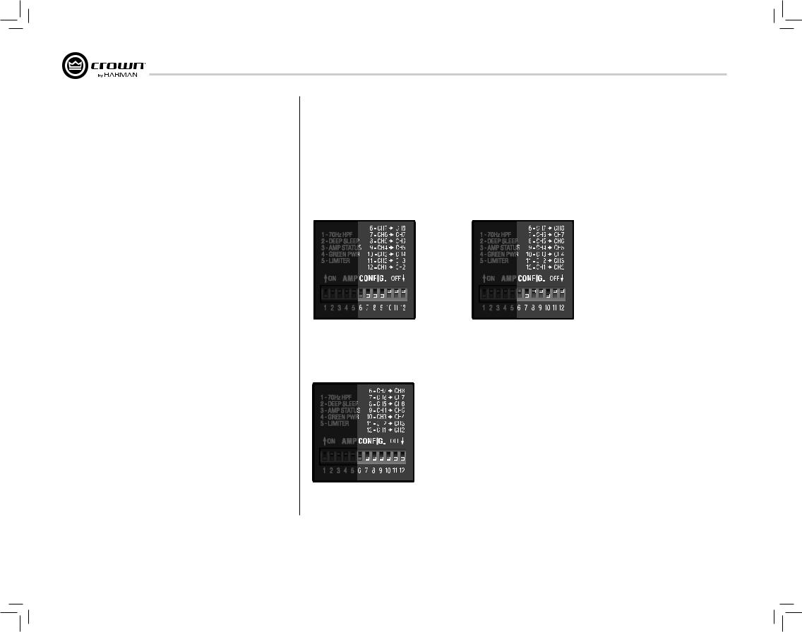
11 Input Routing
This amplifier can route a single channel to the next numbered channel.
In CT 475 and CT 4150, DIP switches 6-9 are non-functional.
When a DIP switch is set to “on” for a specific channel, it sends the signal to its own output AND becomes the input for the next numbered channel, overriding the wired input for that channel.
|
|
|
|
|
|
|
|
|
|
|
|
Figure 11.1 |
Figure 11.3 |
||||
Channel 1 intput sent to all channel |
Channel 1 input sent to channels 1, 2, and 3 |
||||
outputs, overriding channel inputs for |
Channel 4 input sent to channels 4, 5, and 6 |
||||
channels 2,3, and 4 |
Channel 7 input sent to channels 7 and 8 |
||||
|
|
|
|
|
|
|
|
|
|
|
|
|
|
|
|
|
|
Figure 11.2
Four input signals sent to four outputs
Operation Manual

CT Power Amplifiers
13 Advanced Features
13.1 Protection Systems
Your Crown amplifier provides extensive protection and diagnostic capabilities, including thermal level control, fault indicators, high-pass filtering, DC protect, AC under/over voltage protection, inrush limiting, and a convection-cooled chassis.
13.1.1Thermal Indicator
If the amplifier becomes too hot for safe operation, the channel that is generating too much heat will be shut down until the temperature is reduced.
13.1.2 Fault
The amplifier will enter a Fault state if the amplifier senses an unsafe condition. This protection is for both internal and external faults. It is critical to check all wiring to and from the amplifier to ensure the fault is not caused by external conditions. Once wiring has been verified to be correct, and the fault condition persists, see Section 17 Service for Servicing information.
13.1.3 High-Pass Filters
HPF’s are traditionally used in Hi-Z applications. The Com-Tech DriveCore is a low Z amplifier but can be used in conjunction with the XFMR 4/8 transformer box for Hi-Z applications. If the amplifier is to be used in a Hi-Z application, then it is very important to use the HPF to prevent transformer saturation.
13.1.4 AC Under/Over Voltage Protection
If the AC line voltage drops below 25% or rises above 15% of the nominal operating voltage of the amplifier, the amplifier’s power supply turns off and the blue Power LED flashes. The amplifier will turn back on when the AC line voltage returns to safe operating levels (within ±10%).
13.1.5 Circuit Breaker
A circuit breaker located near the IEC power inlet protects the amplifier from excessive AC current draw.
13.1.6 Convection-cooled Chassis
The DriveCore amplifiers require no fans for cooling, providing quiet operation and optimum efficiency.
13.1.7 Auto-Standby
If amplifier does not see input signals for a period of 30 minutes, the amplifier will go into standby mode. The amplifier will come out of standby mode once an input signal is present. This feature is activated via DIP switch #2 on the back of the amplifier. The amplifier will be configured with Auto-Standby turn-on from the factory. When the amplifier is in Standby, the Ready Indicator on the front panel Display will flash.
13.2 Features
13.2.1 Switching Power Supply
Crown’s Switching Power Supply minimizes the amplifier’s weight. Typical non-switching power supplies require large, heavy transformers in order to produce the required power at the output stage. These transformers must be large to operate at 50 to 60 Hz (standard AC supplied by the power company).
By contrast, switching power supplies can operate with a much smaller (and lighter) transformer because they first convert the AC up to a much higher frequency, thereby reducing waste. The power supply is voltage-specific, allowing use in regions using 100V or 240V.
13.2.2 Power Mode
Deep sleep and green mode allow the amplifier to operate at all times with the lowest possible power level.
13.2.3 Adaptive RailTechnology (ART)
Crown has developed a voltage rail technology that delivers power on demand. ART is at the center of CT DriveCore’s Green mode that provides up to an additional 10% of efficiency. Through ART, the CT DriveCore is always operating at maximum efficiency.
13.2.4 DriveCore Power Stage
Crown has worked with Texas Instruments to develop an audio amplifier on a micro-chip. The result is DriveCore chipset that introduces audiophile quality for an installation amp:
-Greater than 90% Efficiency -118dB Signal to Noise
-THD less than .05% in midband frequencies
14 Accessories
14.1 XFMR 4/8
The ComTech DriveCore amplifier is only capable of low Z applications. It is necessary to use an outboard transformer for Hi-Z applications. Crown highly recommends the use of the XFMR 4/8 transformer box. This transformer box is designed to mate with the top of the ComTech DriveCore Amplifiers. See XFMR data sheet for wiring diagram.
14.2 Rack Support Ears
The ComTech DriveCore amplifier requires front and back rack support for proper mounting. These have been provided with the amplifier.
Operation Manual |
page 13 |

CT Power Amplifiers
15 Troubleshooting |
FLASHING |
||
15.1 Power Indicator |
|
CONDITION: Thermal indicator is flashing. |
|
|
POSSIBLE REASON |
||
OFF |
|
||
|
• Amplifier has become too hot to operate. Allow amplifier |
||
|
|
||
|
|||
CONDITION: Power indicator is OFF. |
|
to cool. Amplifier will not pass audio if amplifier has |
|
POSSIBLE REASON |
|
become too hot |
|
|
|
||
• The amplifier has lost AC power. |
|
|
|
• The amplifier’s Power switch is off. |
15.4 Clip Indicator |
||
• The amplifier is not plugged into the power receptacle. |
ON or FLASHING |
||
• The amplifier output level is so high that the power supply |
|||
|
|
||
|
|
||
circuit breaker has tripped. Allow the unit to cool. Turn |
|
CONDITION: Clip indicator is ON or FLASHING. |
|
down the Level controls. Press the Reset Switch on the |
|
POSSIBLE REASON |
|
back panel. |
|
||
|
|
• input level or output level is distorting |
|
FLASHING |
|||
|
|
||
|
|
||
CONDITION: Power indicator is FLASHING.
POSSIBLE REASON
• The AC line voltage has dropped below +15/-25 or has risen above +15/-25% of the nominal line voltage of the power supply.
• Amp is in Deep Sleep Mode.
15.2 Fault Indicator
FLASHING
CONDITION: Fault indicator is FLASHING.
POSSIBLE REASON
• The amplifier channel has stopped operating. Refer the unit to an authorized Crown Service Center.
• Check for shorted outputs
15.3Thermal Indicator
ON
CONDITION:Thermal indicator is ON.
POSSIBLE REASON
• The amplifier is becoming too hot for safe operation.
Allow amplifier to cool. Check for loads less than 4 ohms, and for excessive input levels. Check for proper ventilation and proper mode-switch setting.
15.5 Signal Indicator
OFF
CONDITION: Signal indicator is flashing even though audio is applied, and the channel is ready.
POSSIBLE REASON
•Input signal level is very low
•Level controls are turned down
15.6 Ready Indicator
OFF
CONDITION: Ready indicator is OFF.
POSSIBLE REASON
• Amplifier may be in deep sleep
FLASHING
CONDITION: Ready Indicator flashing.
POSSIBLE REASON
• Amplifier is in Standby mode. Flashing will stop once there is an input signal.
page 14 |
Operation Manual |
ComTech DriveCore Bedienungsanleitung
CT 475
CT 4150
CT 875
CT 8150
Informationen in anderen Sprachen: Für Informationen in einer anderen Sprache zur Verwendung dieses Produkts wenden Sie sich bitte an Ihren lokalen Crown Händler. Wenn Sie bei der Auffindung Ihres lokalen Händlers Hilfe benötigen, kontaktieren Sie bitte Crown unter der Nummer 574-294-8000.
Dieses Handbuch enthält nicht alle Angaben über Konstruktion, Herstellung und unterschiedliche Varianten der Geräte. Darüber hinaus werden nicht alle möglichen Situationen behandelt, die während der Installation, des Betriebs oder der Wartung auftreten können.
Die in diesem Handbuch enthaltenen Informationen galten am Tag der Veröffentlichung. Es können jedoch Aktualisierungen dieser Informationen aufgetreten sein. Für die neueste Version dieses Handbuchs besuchen Sie bitte die Crown Website unter www.crownaudio.com.
Hinweis zum Warenzeichen: Com-Tech, BCA, Crown, Crown Audio, Amcron und Multi-Mode sind eingetragene Warenzeichen von Crown International. IQwic, PIP und PIP2 sind Warenzeichen von Crown International. Andere Warenzeichen sind das Eigentum der jeweiligen Eigentümer.
Einige Modelle werden unter dem Namen Amcron® exportiert.
© 2011 by Harman International®, Inc. 1718 W. Mishawaka Rd., Elkhart, Indiana 46517-9439 U.S.A. Telephone: 574-294-8000
DEUTSCH
143368-2 6/11
CT Power Amplifiers
1 Willkommen
Crown® ComTech DriveCore™ Verstärker bieten Spitzentechnologie für installierte Sound-Anwendungen. ComTech Verstärker bieten geräuschlosen Betrieb, eine kleine Standfläche und eine hervorragende Qualität und Leistung.
ComTech DriveCore Verstärker bieten:
1.1 Features
Audiophilen Sound
•Ein Signal-Rausch-Verhältnis von mehr als 110dB
•Eine harmonische Gesamtverzerrung von weniger als 0,05% auf der gesamten Audiobandbreite
•Mehr als 70dB Übersprechen
•Frequenzgang von ±0.5dB
Vorteilhafte Größe
•Bis zu 8 Kanäle in einem einzelnen Rack
•Gewicht von nur 4,54 kg
Leistungseffizienz
•Mehr als 90% Effizienz in der DriveCore Verstärkerstufe
•Stromverbrauch von weniger als 1W, wenn nicht in Gebrauch (in Deep Sleep)
•Der Green Mode liefert Leistung, wenn sie gebraucht wird. Die Verstärkereffizienz nimmt verglichen mit typischen Verstärkern der Klasse D um 10% zu
Typische Anwendungen für ComTech DriveCore Verstärker sind Vorstandsräume, Videound Telekonferenzen,
VIP-Suites in Stadien und Arenen sowie gehobene Restaurants und Geschäftsräume.
2 Verwendung dieser Bedienungsanleitung
Diese Bedienungsanleitung bietet Ihnen die notwendigen Informationen für die sichere und korrekte Einrichtung und Inbetriebnahme Ihres Verstärkers. Es werden nicht alle Aspekte der Installation, der Einrichtung oder der Inbetriebnahme, die unter allen denkbaren Situationen auftreten können, behandelt. Zusätzliche Informationen finden Sie im Verstärkeranwendungsleitfaden von Crown (Amplifier Application Guide, unter www.crownaudio.com), beim technischen Support von Crown, bei Ihrem Systeminstallateur oder bei Ihrem Händler.
3 Features
•4 oder 8 Kanäle (4 Eingänge mit 4 Ausgängen oder 8 Eingänge mit 8 Ausgängen )
•Einzel-Rack
•Symmetrische 3-Pin-Barriereblockierung/ Leitungseingänge
•4-Pin Phoenix Lautsprecherausgänge
•Flexibles Eingangs-Routing
•Mehrfach-Stromkonfiguration (AutoStandby, Deep Sleep und Green Mode)
•AUX-Anschluss für Verstärkerstatus und Stromsparmodus (Deep Sleep)
•Schutzschalter mit Reset-Schalter
•Konvektorgekühltes Chassis (kein Gebläse)
•Voll übertragbare Dreijahresgarantie auf Fehlerlosigkeit zum kompletten Schutz Ihrer Investition und zur Gewährleitung der technischen Daten.
•Kann für Massenbenachrichtigungssysteme und EN 54 Systeme verwendet werden.
•Patentierte Technologie einschließlich DriveCoreTM
•Fehlerberichte durch AUX-Anschluss
•Adaptive Rail Technology für Leistung nach Bedarf.
•Konform mit Green Edge von Harman
page 16 |
Operation Manual |

CT Power Amplifiers
4 Einrichtung
4.1 Auspacken Ihres Verstärkers
Bitte packen Sie Ihren Verstärker aus und überprüfen Sie ihn auf Schäden, die während des Transports entstanden sein können. Falls Sie Schäden finden, benachrichtigen Sie sofort die Transportfirma. Sie können Schadenersatz nur für Transportschäden beanspruchen. Crown ist Ihnen gerne dabei behilflich. Heben Sie den Versandkarton für die Inspektion durch die Versandfirma als Schadensnachweis auf.
Es wird empfohlen, die Verpackungsmaterialien aufzubewahren, falls Sie das Gerät zu einem späteren Zeitpunkt transportieren müssen.
Versenden Sie das Gerät niemals ohne die Werkverpackung.
SIE BENÖTIGEN (nicht im Lieferumfang enthalten):
•Eingangsverdrahtungskabel
•Ausgangsverdrahtungskabel
•einen flachen Schraubendreher
ein Rack für die Montage des Verstärkers (oder eine stabile Oberfläche zur Stapelanordnung)
ACHTUNG: Vor Inbetriebnahme Ihres Verstärkers lesen und befolgen Sie bitte die wichtigen Sicherheitsanweisungen, die Sie zu Beginn dieser Bedienungsanleitung
finden.
4.2 Installation Ihres Verstärkers
VORSICHT: Stellen Sie vor der Installation sicher, dass Ihr Verstärker von der Stromquelle getrennt ist und alle Regler (siehe Abschnitt 7.6) auf 0 eingestellt sind.
Der Verstärker ist 1,75” hoch, 15.19” tief und 19” breit (siehe Abb. 4.2.1).
Montieren Sie die Einheit in einem standardmäßigen 19-Zoll (48,3 cm) Rack (EIA RS-310B). Sie können einen einzelnen Verstärker ebenfalls auf einer festen stabilen Oberfläche anordnen oder mehrere Verstärker übereinander anordnen.
ANMERKUNG: Beim Transport sind die Verstärker vorne und hinten zu stützen.
4.3 Sicherstellen einer korrekten Kühlung
Bei Verwendung eines Rack montieren Sie die Einheiten direkt übereinander. Verschließen Sie Freiräume im Rack mit Blindplatten. Blockieren Sie die Belüftungen an der Vorderseite, der Oberseite und an den Seiten NICHT.
Die Seitenwände des Rack müssen einen Mindestabstand von 5,1 cm (2 Zoll) zu den Seitenwänden des Verstärkers aufweisen und die Rückseite des Rack muss mindestens 10,2 cm (4 Zoll) von der Rückseite des Verstärkers entfernt sein. Da der Verstärker konvektorgekühlt ist und kein Gebläse benötigt, ist es besonders wichtig, dass die Belüftungen nicht verdeckt sind.
Abb. 4.2.1 Abmessungen der CT Serie
Operation Manual |
page 17 |
CT Power Amplifiers
4Einrichtung
4.4Eingangsdrähte und Stecker wählen
Crown empfiehlt vorgefertigte bzw. professionell verdrahtete symmetrische Leitungen (zwei Leiter mit Abschirmung). Eine symmetrische Verdrahtung bietet einen besseren Schutz vor unerwünschtem Rauschen und Brummen. Es kann jedoch auch eine nicht symmetrische Leitung verwendet werden. Weitere Informationen finden Sie im Crown Verstärkeranwendungsleitfaden, der bei www. crownaudio.com erhältlich ist.
Verwenden Sie an den Verstärkereingangsanschlüssen 3-Pin Phoenix Kabelenden.
Abb. 4.4.1 zeigt Pin-Zuordnungen der Stecker für eine symmetrische Verdrahtung und Abb. 4.4.2 zeigt Pin-Zuordnungen der Stecker für eine nicht symmetrische Verdrahtung.
ANMERKUNG: Individuelle Verdrahtungen sind nur von qualifizierten Fachkräften durchzuführen. Es ist eine Verdrahtung der Klasse 2 erforderlich.
SYMMETRISCHE |
ASYMMETRISCHE |
|||||||||||||||||||
LEITUNG |
LEITUNG |
|||||||||||||||||||
|
|
|
|
|
|
|
|
|
|
EINGANG |
|
|
|
|
|
|
|
|
|
EINGANG |
|
|
|
|
|
|
|
|
|
|
|
|
|
|
|
|
|
|
|
||
|
|
|
|
|
|
|
|
|
|
|
|
|
|
|
|
|
|
|
||
|
|
|
|
|
|
|
|
|
|
|
|
|
|
|
|
|
|
|
||
|
|
|
|
|
|
|
|
|
|
|
|
|
|
|
|
|
|
|
||
|
|
|
|
|
|
|
|
|
|
|
|
|
|
|
|
|
|
|
|
|
|
|
|
|
|
|
|
|
|
|
|
|
|
|
|
|
|
|
|
|
|
4.5 Ausgangsdrähte und Stecker wählen
Crown empfiehlt professionell gefertigte Qualitätslautsprecherkabel und Stecker mit zwei Leitern und großem Durchmesser. Verwenden Sie 2-Pin Phoenix Stecker (im Lieferumfang enthalten).
Unten finden Sie Richtlinien für die Auswahl der korrekten Kabelgröße basierend auf der Entfernung zwischen Verstärker und Lautsprecher. Erkundigen Sie sich nach lokalen Vorschriften, da diese variieren können.
Entfernung |
Kabelgröße |
bis zu 7,6 m |
16 AWG |
7,9 bis 12,2 m |
14 AWG |
VORSICHT: Verwenden Sie niemals abgeschirmte Kabel für die Ausgangsverdrahtung.
VORSICHT: Schließen Sie die Rückleitung des Lautsprechers niemals am Chassis des Verstärkers an, da dadurch der Verstärker beschädigt werden kann.
VORSICHT: Der Ausgang der Verstärkerkanäle kann nicht überbrückt werden. Dadurch kann der Verstärker beschädigt werden.
QUELLE QUELLE
Abb. 4.4.1 Abb. 4.4.2
page 18 Operation Manual
CT Power Amplifiers
4Einrichtung
4.6Verdrahtung Ihres Systems
Bevor Sie Ihr System verdrahten, müssen Sie sich mit den Fähigkeiten des Eingangs-Routing vertraut machen.
Der DriveCore Verstärker kann auf zwei Weisen konfiguriert werden:
1. Der Eingang für einen Kanal geht aus demselben Kanal heraus. Diese Option ist die Standardkonfiguration.
CHANNEL 1 |
RIVED |
CHANNEL 1 |
||
|
|
|
|
|
CHANNEL 2 |
|
|
OREC |
CHANNEL 2 |
|
||||
|
|
|
|
|
CHANNEL 3 |
|
|
MPLIFIERA |
CHANNEL 3 |
|
||||
CHANNEL 4 |
|
|
CHANNEL 4 |
|
|
|
|
||
|
|
|
|
|
Abb. 4.6.1 Vier Kanäle ohne Eingangs-Routing
CHANNEL 1 |
RIVED |
CHANNEL 1 |
||
|
|
|
|
|
CHANNEL 2 |
|
|
OREC |
CHANNEL 2 |
|
||||
|
|
|
|
|
CHANNEL 3 |
|
|
MPLIFIERA |
CHANNEL 3 |
|
||||
CHANNEL 4 |
|
|
CHANNEL 4 |
|
|
|
|
||
CHANNEL 5 |
|
|
|
CHANNEL 5 |
|
|
|||
CHANNEL 6 |
|
|
|
CHANNEL 6 |
|
|
|||
CHANNEL 7 |
|
|
|
CHANNEL 7 |
|
|
|||
CHANNEL 8 |
|
|
|
CHANNEL 8 |
|
|
|||
|
|
|
|
|
Abb. 4.6.2 Acht Kanäle ohne Eingangs-Routing
Operation Manual
2. Der Eingang für einen Kanal kann zum nächsten Kanal geleitet werden, wobei das verdrahtete Eingangssignal für diesen Kanal übergangen wird. Durch dieses Verfahren wird die Eingangsverdrahtung vereinfacht und die Verwendung von Y-Kabeln minimiert.
CHANNEL 1 |
RIVED |
CHANNEL 1 |
|||
CHANNEL 2 |
CHANNEL 2 |
||||
OREC |
|||||
|
|
|
|
||
CHANNEL 3 |
|
|
MPLIFIERA |
CHANNEL 3 |
|
|
|||||
CHANNEL 4 |
CHANNEL 4 |
||||
|
|||||
|
|
|
|
|
|
Abb. 4.6.3 Zwei-Kanal zu Vier-Kanal-Routing
CHANNEL 1 |
RIVED |
CHANNEL 1 |
|
CHANNEL 2 |
CHANNEL 2 |
||
OREC |
|||
|
|
||
CHANNEL 3 |
MPLIFIERA |
CHANNEL 3 |
|
CHANNEL 4 |
CHANNEL 4 |
||
|
|||
|
|
|
Abb. 4.6.4 Ein-Kanal zu Vier-Kanal-Routing
CHANNEL 1 |
RIVED |
CHANNEL 1 |
|||
CHANNEL 2 |
CHANNEL 2 |
||||
OREC |
|||||
|
|
|
|
||
CHANNEL 3 |
|
|
MPLIFIERA |
CHANNEL 3 |
|
|
|||||
CHANNEL 4 |
CHANNEL 4 |
||||
|
|||||
CHANNEL 5 |
|
|
|
CHANNEL 5 |
|
|
|
||||
CHANNEL 6 |
|
CHANNEL 6 |
|||
CHANNEL 7 |
|
|
|
CHANNEL 7 |
|
|
|
||||
CHANNEL 8 |
|
CHANNEL 8 |
|||
|
|
|
|
|
|
4.7 Anschluss an Netzstrom
Schließen Sie Ihren Verstärker mit dem mitgelieferten
Stromkabelsatz an den Netzstrom (Steckdose) an.
Stecken Sie zuerst das IEC-Ende des Kabelsatzes in die IEC-Buchse am Verstärker und stecken Sie danach das andere Ende des Kabelsatzes in die Netzsteckdose ein.
ACHTUNG: Der dritte Zinken dieses Steckers (Erde) ist ein wichtiges Sicherheitsmerkmal. Versuchen Sie nicht, diesen Erdanschluss mit Hilfe eines Adapters oder anderer Verfahren unwirksam zu machen.
Verstärker erzeugen keine Energie. Netzspannung und Netzstrom müssen für die Leistung, die Sie erwarten, ausreichen. Wenn die Netzspannung über einen akzeptablen Bereich hinaus schwankt, wird die Stromversorgung des Verstärkers ausgeschaltet und die blaue Strom-LED blinkt. Der Verstärker schaltet sich wieder ein, wenn die Netzspannung wieder sichere Betriebspegel erreicht.
Abb. 4.7.1 zeigt Spannungsgrenzwerte für alle AC-Spannungskonfigurationen des Verstärkers. Darüber hinaus muss der Verstärker innerhalb der angegebenen Netzfrequenzwerte betrieben werden (siehe Rückseite des Verstärkers). Wenn Sie sich hinsichtlich der Ausgangsspannung Ihres Netzanschlusses nicht sicher sind, fragen Sie Ihren Elektriker.
Modell |
Unterspannungsgrenzwert |
Überspannungsgrenzwert |
|
|
|
Alle Modelle |
90 VAC |
264 VAC |
|
|
|
Abb. 4.7.1 AC Unterund Überspannungsgrenzwerte für verschiedene Verstärkermodelle
Abb. 4.6.5 Vier-Kanal zu Acht-Kanal-Routing
Das Eingangs-Routing wird mit Hilfe der DIP-Schalter an der Rückseite des Verstärkers konfiguriert. Siehe
Abschnitt 11 - Eingangs-Routing - für Informationen zur Konfiguration der Schalter.
Anmerkung: ComTech DriveCore Verstärker können NICHT überbrückt werden.
page 19

CT Power Amplifiers
4Einrichtung
4.8Inbetriebnahme
Für die erste Inbetriebnahme Ihres Verstärkers:
1.Regeln Sie den Pegel Ihrer Audioquelle herunter.
2.Regeln Sie die Pegelregler des Verstärkers herunter (siehe Abschnitt 7.6).
3.Schalten Sie den "Power"-Schalter ein. Die Stromanzeige leuchtet.
4.Regeln Sie den Pegel Ihrer Audioquelle auf einen optimalen Pegel hoch.
5.Regeln Sie die Pegelregler am Verstärker hoch, bis die gewünschte Lautstärke oder der gewünschte Leistungspegel erreicht ist.
Falls Sie Veränderungen an der Verdrahtung oder der Installation vornehmen müssen, schalten Sie den Verstärker stets aus und klemmen Sie das Stromkabel ab.
Hilfe bei der Ermittlung der optimalen Verstärkungsstruktur (Signalpegel) finden Sie im Crown
Verstärkeranwendungsleitfaden bei www.crownaudio.com.
5 Vorsichtsmaßnahmen
Ihr Verstärker ist gegen interne und externe Fehler geschützt. Jedoch sind folgende Vorsichtsmaßnahmen für eine optimale Leistung und Sicherheit zu befolgen:
1.Vor Gebrauch muss Ihr Verstärker für einen korrekten Betrieb konfiguriert werden, einschließlich Eingangsund Ausgangsverdrahtung. Eine inkorrekte Verdrahtung kann ernsthafte Betriebsprobleme verursachen. Informationen zur Verdrahtung und Konfiguration finden Sie im Abschnitt "Einrichtung" dieses Handbuchs. Weitere Informationen finden Sie im Crown Verstärkeranwendungsleitfaden bei www.crownaudio.com.
2.Gehen Sie bei dem Anschluss, der Auswahl der Signalquellen und der Regelung der Ausgangsregler vorsichtig vor. Dadurch vermeiden Sie zukünftige Probleme.
3.Schließen Sie nicht die Erdleitung eines Ausgangskabels mit der Erdung des Eingangssignals kurz. Dadurch kann eine Erdungsschleife entstehen und es können Schwingungen erzeugt werden.
4.Schließen Sie den Ausgang niemals an eine Stromversorgung, an eine Batterie oder an das Stromnetz an. Es besteht die Gefahr von Stromschlägen.
5.Durch Manipulation und unbefugte Änderungen am Schaltkreis können Gefahren entstehen und sämtliche Zulassungen werden ungültig.
6.Betreiben Sie den Verstärker nicht, wenn die rote Überlastungs-LED fortwährend blinkt.
7.Übersteuern Sie nicht den Mischer, da dadurch ein überlastetes Signal zum Verstärker gesendet wird. Derartige Signale werden äußerst exakt wiedergegeben, wodurch die Lautsprecher beschädigt werden können.
8.Betreiben Sie den Verstärker nicht bei einer geringeren Impedanz als der angegebenen Lastimpedanz. Aufgrund des Ausgangsschutzes des Verstärkers kann eine solche Konfiguration zu einer vorzeitigen Überlastung und Lautsprecherschäden führen.
9.Der Ausgang des Verstärkers kann nicht überbrückt werden und mehrere Kanäle können nicht miteinander verbunden werden.
Beachten Sie: Crown ist für Schäden aufgrund von Übersteuern anderer Systemkomponenten nicht haftbar.
page 20 |
Operation Manual |
 Loading...