


ASC-2E
W 1 6 4 N 9 2 2 1 W a t e r S t r e e t • P. O . B o x 45 0 • M e n o m o n e e F a l l s , W i s c o n s i n 5 3 0 5 2 - 0 4 5 0 U S A
PHONE: 262.251.3800 • 800.558.8744
USA/CANADA FAX: 262.251.7067 • 800.329.8744 U.S.A. ONLY
WEBSITE: www.alto-shaam.com
P RI N TE D I N U . S .A .
®
Model:
ASC-2E
ASC-4E
Manual
Control
C o n v e c t i o n O v e n
E l e c t r i c
• I N STALLATI O N
• OP E RAT ION
• MAI NT ENAN C E
AS C- 2E
WI TH
Mobile Stand Option 5004687
AS C- 4E
WI TH
Stand Option 5003489
#87 01/ 2 • 11 /07
D E L I V E R Y
T
his Alto-Shaam appliance has been
t
horoughly tested and inspected to insure only the
h
ighest quality unit is provided. Upon receipt,
c
heck for any possible shipping damage and
report it at once to the delivering carrier. Se e
Transportation Dam ag e and Claim s section located
in this manu al.
This appliance, complete with unattached
items and accessories, may have been delivered in
one or more packages. Check to ensure that all
standard items and options have been received
with each model as ordered.
Save all the information and instructions
packed with the appliance. Complete and return
the warranty card to the factory as soon as
possible to assure prompt service in the event of a
warranty parts and labor claim.
This manual must be read and understood by
all people using or installing the equipment
model. Contact the Alto-Shaam service
department if you have any questions concerning
installation, operation, or maintenance.
NO TE: All claims for warranty must include the
full model number and serial number of
the unit.
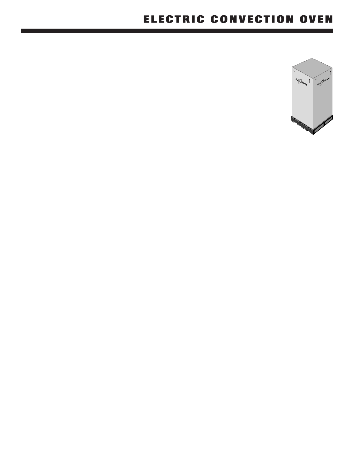
U N PA C K I N G
1. Carefully remove the
appliance from the
carton or crate.
N
OTE: Do not discard the
carton and other
packaging material
until you have
inspected the unit for
hidden damage and
tested it for proper
operation.
2. Read all instructions in this manual carefully
before initiating the installation of this appliance.
DO NOT DISCARD THIS M ANUAL.
This manual is considered to be part of the
appliance and is to be provided to the owner
or manager of the business or to the person
responsible for training operators. A d d itional
manuals are available from the Alto-Shaam
service dep artmen t.
3. Remove all protective plastic film, packaging
materials, and accessories from the appliance
before connecting electrical power. Store any
accessories in a convenient place for future use.
#8701/2 Electric Convection Oven - Manual Control • 1
®
®
#8701/2 Electric Convection Oven - Manual Control • 2
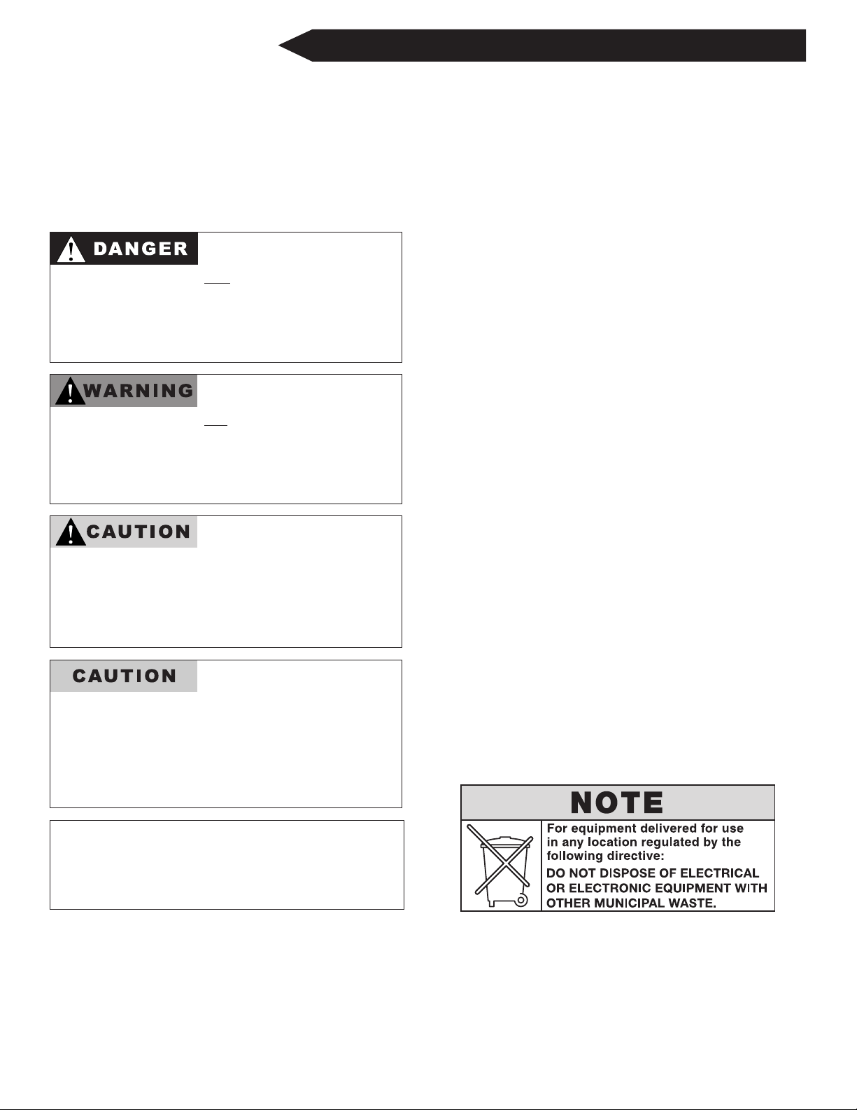
SAF ETY PROCEDURES
A N D P R E C A U T I O N S
K
nowledge of proper procedures is essential to the
s
afe operation of electrically energized equipment.
I
n accordance with generally accepted product
s
afety labeling guidelines for potential hazards,
t
he following signal words and symbols may be
u
sed throughout this manual.
Used to indicate the
presence of a hazard that
will
cause severe personal
injury, death, or substantial
property damage if the
warning included with this
symbol is ignored.
Used to indicate the
presence of a hazard that
can cause personal injury,
possible death, or major
property damage if the
warning included with this
symbol is ignored.
Used to indicate the
presence of a hazard that
can or will cause minor or
moderate personal injury
or property damage if the
warning included with this
symbol is ignored.
Used to indicate the
presence of a hazard that
can or will cause minor
personal injury, property
damage, or a potential
unsafe practice if the
warning included with this
symbol is ignored.
Used to notify personnel of
installation, operation, or
maintenance information that is
important but not hazard related.
1. This appliance is intended to cook, hold or
process foods for the purpose of human
consumption. No other use for this
appliance is authorized or recommended.
2. This appliance is intended for use in
commercial establishments where all
operators are familiar with the purpose,
limitations, and associated hazards of this
appliance. Operating instructions and
warnings must be read and understood by
all operators and users.
3. Any troubleshooting guides, component
views, and parts lists included in this manual
are for general reference only and are intended
for use by qualified technical personnel.
4. This manual should be considered a
permanent part of this appliance. This
manual and all supplied instructions,
diagrams, schematics, parts lists, notices, and
labels must remain with the appliance if the
item is sold or moved to another location.
NOTE:

#8701/2 Electric Convection Oven - Manual Control • 3
S I T E I N S T A L L A T I O N
This appliance must be
installed in a location that will
permit the oven to function
for its intended purpose and
to allow adequate clearance
for ventilation, proper
cleaning, and maintenance
access.
1. Hood installation is recommended. (
CH ECK
LO CAL CODE S
).
2. The oven must be installed on a stable and
level surface.
3. DO NOT install this oven in any area where it may
be affected by any adverse conditions such as steam,
grease, dripping water, high temperatures, etc.
4. DO NOT store or use any flammable liquids or
allow flammable vapors in the vicinity of this
oven or any other appliance.
5. This appliance must be kept free and clear of any
combustible materials.
6. This appliance must be kept free and clear of
any obstructions blocking access for maintenance
or service.
I N S T A L L AT I O N S A F E T Y W A R N I N G
®
METAL PARTS OFTHIS EQUIPMENT
BECOME EXTREMELY HOT WHEN IN
O
PERATION. TO AVOID BURNS,
ALWAYS USE HAND PROTECTION
WHEN OPERATING THIS APPLIANCE.
DO NOT store or use any
flammable liquids or allow
flammable vapors in the vicinity of
any appliance.
DO NOT LIFT OR MOVE THE
OVEN BY USING THE DOORS
OR THE DOOR HANDLES.
A S C - 2 E • W E I G H T
NET: 250 lb (113 kg) EST. SHIP: 325 lb ( 147 kg) EST.
CRATE 44" H X 42" W X 42" D
D I M E NSI O N S: (1118mm x 1067mm x 1067mm)
MINIMUM ENTRY CLEA RANCE 31" (787mm) UNCRATE D
A S C - 2 E • D I M E N S I O N S : H x W x D
EXTERIOR: 32-1/8" x 30" x 30-1/8" (815mm x 762mm x 815mm)
INTE RIOR: 20" x 15" x 21" (508mm x 381mm x 533mm)
A S C - 4 E • W E I G H T
NET: 393 lb (178 kg) EST. SHIP: 438 lb ( 199 kg)
CRATE 40" H X 44" W X 53" D
D I M E NSI O N S: (1016mm x 1118mm x 1346mm)
MIN. ENTRY CLE ARANCE 31-1/2" (800mm) UNCRATED
W/O L EGS
A S C - 4 E • D I M E N S I O N S : H x W x D
EXTERIOR: 57-1/2" x 38" x 44-1/2" (1461mm x 965mm x 1130mm)
INTE RIOR: 24" x 29-1/8" x 25" (610mm x 740mm x 635mm)
M I N I M U M C L E A R A N C E R E Q U I R E M E N T S
BA CK 0" (0mm)
LE FT SI DE 2" (51mm)
RI GH T SID E 2" (51mm)
FROM GREASE PRODUCING EQUIPMENT 6" (152mm)
RE CO MM EN DE D SER VI CE ACC ES S: 20" (508mm) RI GHT SI DE
Where automatically operated appliances are vented
through a ventilating hood or exhaust system
equipped with a damper or with a power means of
exhaust, provisions shall be made to allow the
equipment to operate only when the damper is open
to a position to properly vent the appliance and
when the power means of exhaust is in operation.
A CCORD ANCE WI TH NF PA 5 4 CO MM ON WEAL T H O F
M ASSAC HUSE TTS ONLY
.
#8701/2 Electric Convection Oven - Manual Control • 4
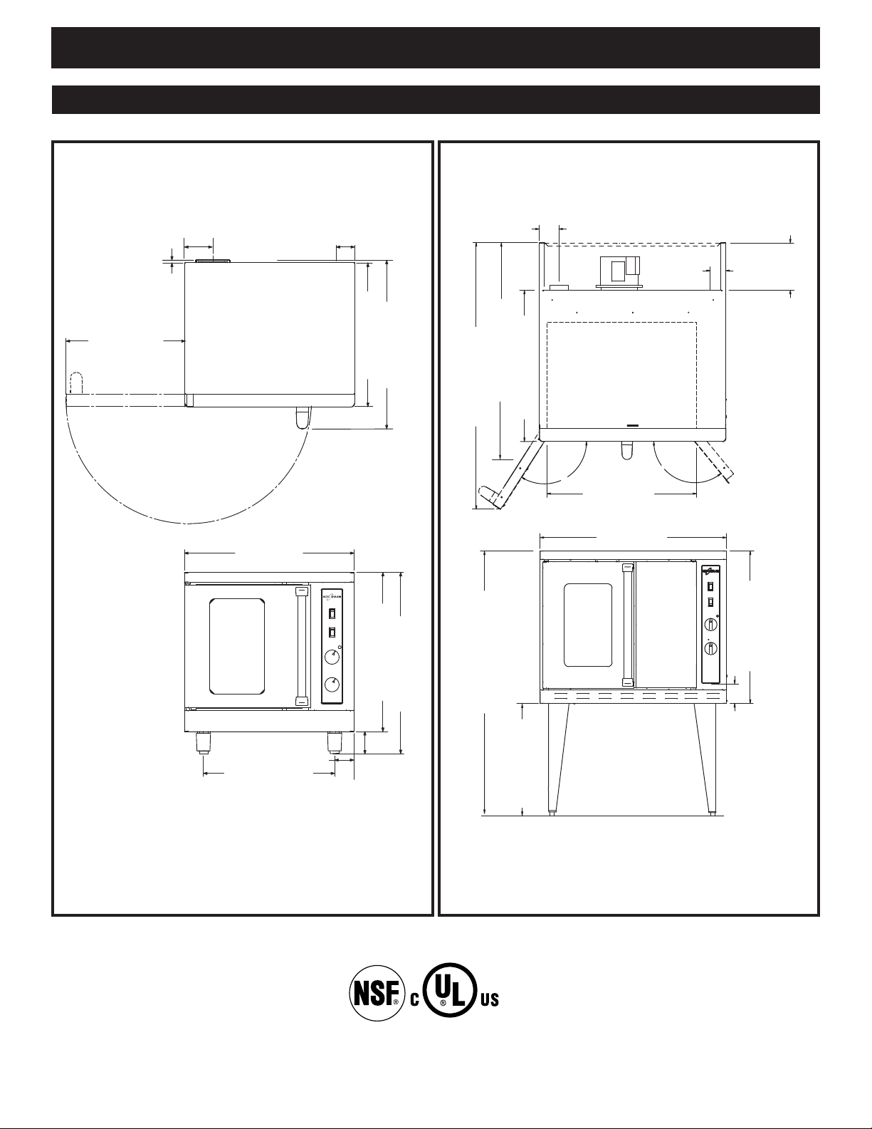
30-5/8" (778mm)
8" (203mm)
CAVITY VENT
ELECTRICAL
I
NLET
3-5/32"
(80,1mm)
9-15/16" (252mm)
ELECTRICAL ENTRANCE
1
23?
129?
29" (737mm)
CAVITY WIDTH
38" (965mm)
31-1/16" (789mm)
4" (102mm)
ELECTRICAL INLET
54-5/8" (1387mm)
44-1/2" (1130mm)
26-
1/
2"
(
673mm)
57-1/2" (1461mm)
30" (762mm)
28-3/16" (715mm)
3-15/16" (100mm)
32-1/8" (815mm)
3-3/8" (86mm)
23-1/4" (590mm)
4-11/16"
(
119mm)
1"
(25mm)
21-1/8 (536mm)
3-1/4"
(
83mm)
25-7/16 (646mm)
30-1/8" (815mm)
Exhaust
E
lectrical
2
" (51mm)
from bottom
LISTED
COOKING APPLIANCE
49ZA
I N S TA L L A T I O N
E X T E R I O R D I M E N S I O N S
A S C - 2 E A S C - 4 E
#8701/2 Electric Convection Oven - Manual Control Pg. 5.
A number of adjustments are associated with
initial installation and start-up. It is important
that these adjustments be conducted by a qualified
service technician. Installation and start-up
adjustments are the responsibility of the dealer or
user. These adjustments include but are not
limited to thermostat calibration, door adjustment,
leveling, and moisture vent installation.
All clearances for proper ventilation air supply
must be maintained to minimize fire hazard. Do
not locate the oven immediately adjacent to any
other heat generating appliance.
Inadequate ventilation may
result in a high ambient
temperature at the rear of the oven. An excessive
ambient temperature can cause the thermal-
overload protection device on the blower motor to
trip resulting in severe damage to the blower
motor.
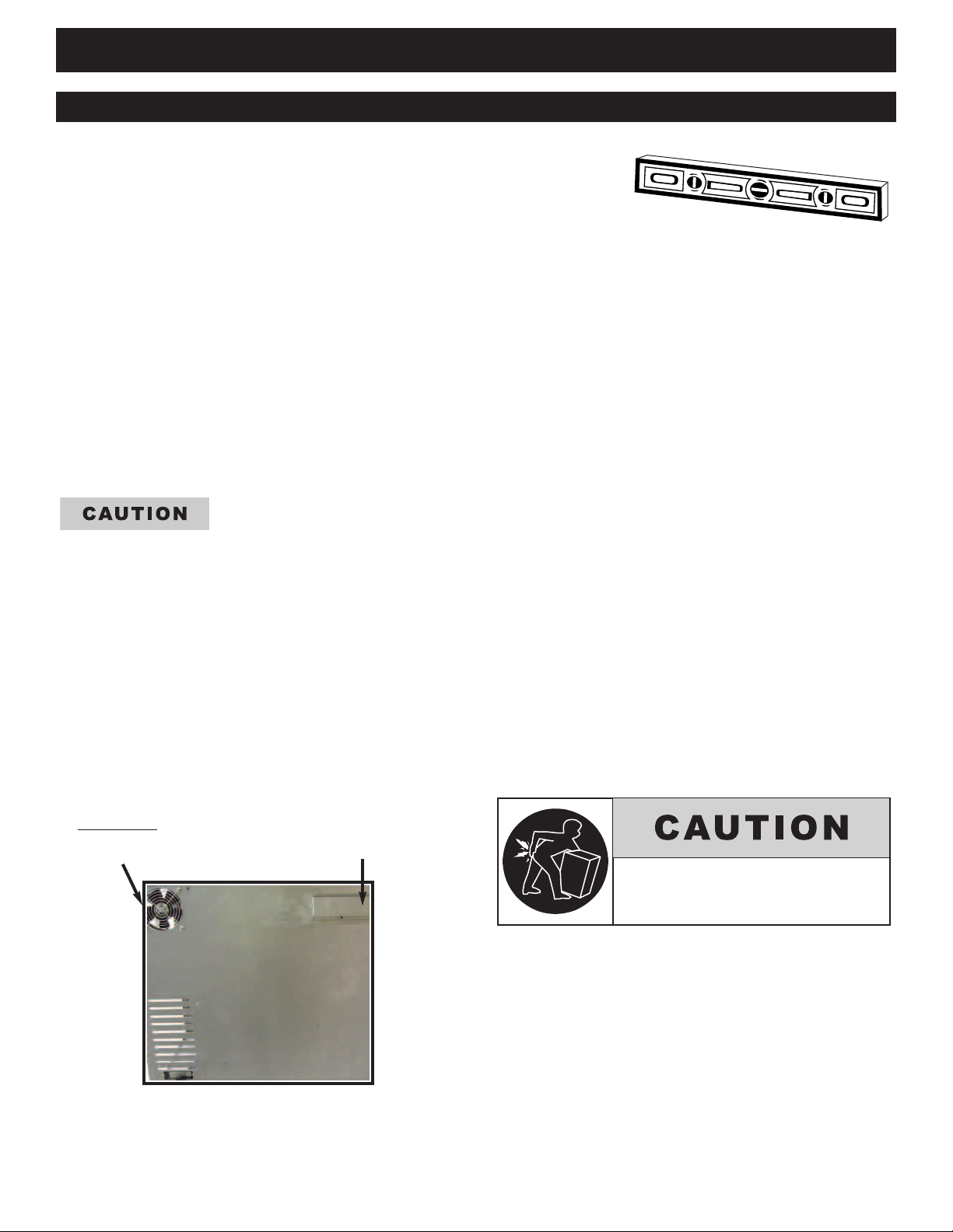
LEV ELING
Level this appliance from side-
to-side and front-to-back with the use of a spirit
level. For ovens installed on a mobile stand, it is
important that the installation surface be level due
to the probability of frequent oven repositioning.
We recommend checking the level of the appliance
periodically to make certain the floor has not
shifted nor the appliance moved.
NOTE: Failure to properly level this oven can
cause improper function and will result
in the uneven baking of products
consisting of semi-liquid batter.
I N S T A L L AT I O N R E Q U I R E M E N T S
I N S T A L L A T I O N
MOISTUR E
VENT
ON BACK OF
OVEN
CO OL ING FAN
FA-3568
FAN GUA RD
GD-2396
TO PREVENT PERSONAL INJURY,
USE CAUTION WHEN MOVING OR
LEVELING THIS APPLIANCE.
#8701/2 Electric Convection Oven - Manual Control • 6
I N S T A L L AT I O N R E Q U I R E M E N T S
I N S TA L L A T I O N
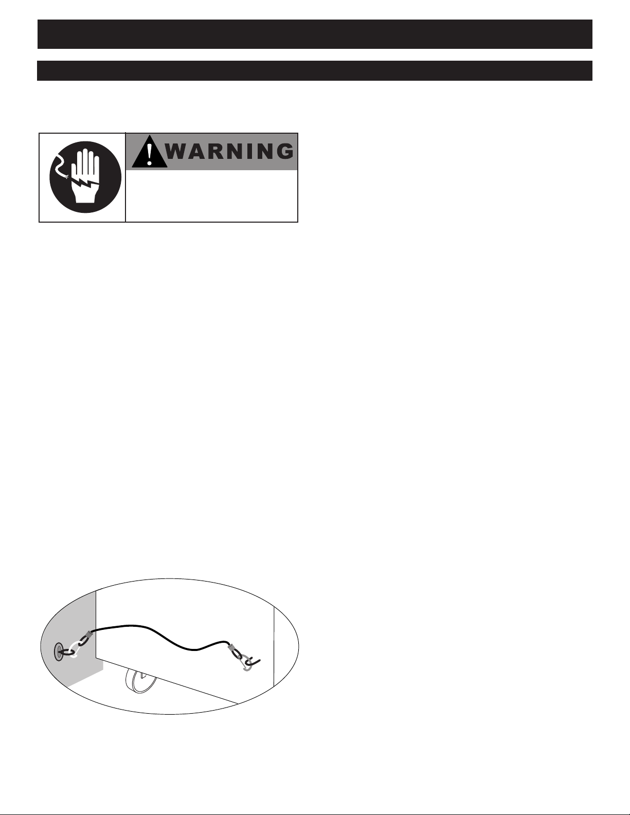
RESTRAINT REQUIREMENTS
—MOBILE EQUIPMENT
Any appliance that is not furnished with a power
supply cord but includes a set of casters must be
provided with a tether. Adequate means must be
provided to limit the movement of this appliance
without depending on or transmitting stress to the
electrical conduit. The following requirements
apply:
1. Casters must be a maximum height of
6" (152mm).
2. Two of the casters must of be the
locking type.
3. Such mobile appliances or appliances on
mobile stands must be installed with the
use of a flexible connector secured to the
building structure.
A mounting connector for a restraining device is
located on the lower back flange of the appliance
chassis or on an oven stand, approximately 18"
(457mm) from the floor. A flexible connector is
not supplied or available from the factory.
RISK OF ELECTRIC SHOCK.
Appl iance must be secured
to build ing structure.
#8701/2 Electric Convection Oven - Manual Control Pg. 7.
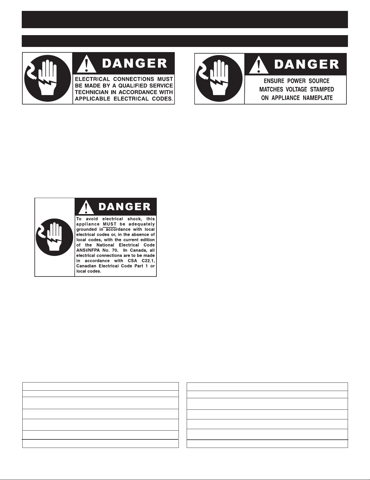
The oven must be installed by a qualified
electrician. This appliance must be branch circuit
protected with proper ampacities, in accordance
with the wiring diagram located in this manual or
in the electrical compartment of the oven. The
oven must be properly grounded in accordance
with the National Electrical Code and applicable
local codes.
Plug the unit into a properly grounded receptacle
ONLY, positioning the unit so that the plug is
easily accessible in case of an emergency. Arcing
will occur when connecting or disconnecting the
unit unless all controls are in the “off” position.
Proper receptacle or outlet configuration or
permanent wiring for this unit must be installed
by a licensed electrician in accordance with
applicable local electrical codes.
Wire size for the main incoming power to the
unit must match the minimum size listed in the
specifications applicable to the specific oven
model. For supply connections, locate the wire
size posted on the label located near the electric
terminal block behind the service panel or
elsewhere listed in this manual. Before
attempting the electrical connection, the rating
plate should be checked to ensure that the
electrical characteristics of the appliance and the
electrical supply characteristics agree.
Installation of the wiring must be made in
accordance with U.L. 197 Commercial Electric
Cooking Appliance Standards, Local and/or
National Electrical Code, ANSI /NFPA 70-1990.
Service line entry is made through the rear of the
oven for connection to the terminal block.
Remove the service panel on the right side of the
oven for access to the terminal block.
The oven is wired at the factory for either single
phase or three phase service as indicated on the
original purchase order. Input voltage and phase
must match the voltage and phase of the oven.
Visually check all electrical connections.
E L E C T R I C A L C O N N E C T I O N
I N S TA L L A T I O N
E L E C T R I C A L • A C S - 2 E
VOLTAGE PHASE CYCLE/ HZ AWG AMPS kW
208 1 50/60 10 25.5 5.3
240 1 50/60 10 22.0 5.3
208 3 50/60 12 14.7 5.3
240 3 50/60 12 12.8 5.3
N O CO RD A N D P L U G
E L E C T R I C A L • A S C - 4 E
VOLTAGE PHASE CYCLE/ HZ AWG AMPS kW
208 1 50/60 6 50.0 10.4
240 1 50/60 6 43.3 10.4
208 3 50/60 8 25.0 10.4
240 3 50/60 8 25.0 10.4
N O CO RD A N D P L U G
#8701/2 Electric Convection Oven - Manual Control • 8
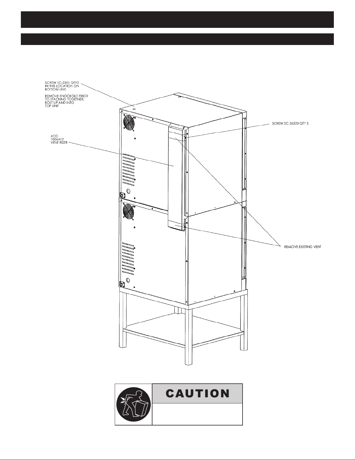
I N S TA L L A T I O N
S T A C K I N G & V E N T I N G A S S E M B L Y f o r 2 - A S C - 2 E / S T K
TO PREVENT PERSONAL INJURY,
USE CAUTION WHEN MOVING OR
LEVELING THIS APPLIANCE.
2 - A S C - 2 E / S T K
Stand
#5004672
 Loading...