


Technical Manual
Hood-Type
Dishwasher
Models Included:
VC1000
October, 2003 |
Valu-Clean Manual P/N 113566 Rev. A |
||
P.O. Box 4982 |
|
2674 N. Service Road |
|
Winston-Salem, NC 27115 |
Jordan Station, Ontario, Canada L0R 1S0 |
||
336/661-1559 |
Fax: 336/661-1979 |
905/562-6630 |
Fax: 905/562-5422 |
valu-clean.com
Complete the information below so it will be available for quick reference.
Model Number |
|
|
|
Serial Number |
|
|
|
|
Voltage and Phase |
|
|
|
|
|
|
|
|
Valu-Clean Service Agency |
|
|
Phone |
|
|
|||
|
|
|
|
|||||
Valu-Clean Parts Source |
|
Phone |
|
Valu-Clean (Canada) |
Valu-Clean (U.S.A.) |
|
National Service Department |
National Service Department |
|
Phone: |
1 (905) 562-4195 |
|
Phone: |
1 (336) 661-1559 |
|
|
1 (800) 263-5798 |
|
Fax: |
1 (905) 562-4618 |
Fax: 1 (336) 661-1979 |
We strongly recommend that you Fax your orders.
NOTE: When calling to order parts, be sure to have the model number, serial number, voltage
of your machine.
 Model and Serial number located
on the right side of the control cabinet.
COPYRIGHT © 2003 byValu-Clean

REVISION HISTORY
Revision History
Revision |
Revised |
Serial Number |
Comments |
Date |
Pages |
Effectivity |
|
|
|
|
|
8/01/02 |
— |
|
First issue of manual and replacement parts |
|
|
|
|
10/13/03 |
iii |
— |
Added new figure number |
|
|
|
|
10/13/03 |
16-17 |
— |
Added corner configuration instructions |
|
|
|
|
i

REVISION HISTORY
Revision History (Cont)
ii

|
TABLE OF CONTENTS |
|
CONTENTS |
|
Page |
REVISION HISTORY...................................................................................................................... |
i |
SAFETY SYMBOLS ...................................................................................................................... |
v |
GENERAL SPECIFICATIONS ...................................................................................................... |
1 |
INSTALLATION .............................................................................................................................. |
2 |
Electrical Connections ........................................................................................................ |
2 |
Water Connections .............................................................................................................. |
3 |
Drain Connections .............................................................................................................. |
3 |
Ventilation............................................................................................................................ |
3 |
Chemical Connections ........................................................................................................ |
4 |
INITIAL START-UP ........................................................................................................................ |
5 |
OPERATION .................................................................................................................................... |
5 |
DAILY CLEANING........................................................................................................................ |
6 |
MAINTENANCE ............................................................................................................................ |
7 |
TROUBLESHOOTING.................................................................................................................... |
8 |
REPLACEMENT PARTS .............................................................................................................. |
11 |
ELECTRICAL SCHEMATICS ...................................................................................................... |
29 |
|
|
|
|
LIST OF FIGURES |
Figure |
1 |
— |
Door Assembly ........................................................................................ |
12 |
Figure |
2 |
— |
Wash/Rinse Assembly .............................................................................. |
14 |
Figure |
3 |
— |
Corner Conversion.................................................................................... |
16 |
Figure |
4 |
— |
Drain/Pump Assembly.............................................................................. |
18 |
Figure |
5 |
— |
Pump Assembly........................................................................................ |
20 |
Figure |
6 |
— |
Piping Assembly ...................................................................................... |
22 |
Figure |
7 |
— |
Control Panel............................................................................................ |
24 |
Figure |
8 |
— |
Control Cabinet ...................................................................................... |
26 |
iii

THIS PAGE
INTENTIONALLY LEFT BLANK
iv
SAFETY SYMBOLS
Safety Symbols
•The following symbols appear throughout this manual alerting you to potential hazards. Statements associated with each symbol are printed in italics.
WARNING:
Warning statements indicate any condition or practice that could result in personal injury or possible loss of life.
CAUTION:
!Caution statements indicate any condition or practice which, if not strictly observed or remedied, could result in damage to or destruction of the equipment.

 NOTE:
NOTE:
Note statements indicate any condition or practice which, if observed, will help in the safe completion of a task.
General Safety Rules
•The following general safety rules must be observed in addition to the specific cautions and warnings presented in this manual.
•Operators should use caution when loading and unloading wares from the equipment.
•Operators must NOT bypass a safety interlock or control(s) to operate the dishwasher.
•The service and maintenance instructions contained in this manual are intended for qualified service personnel. These instructions assume that you are trained in basic electricity and mechanical theory. If you are not a trained technician, then do not attempt to adjust or repair the equipment as serious personal injury or damage to the equipment may result.
v

THIS PAGE
INTENTIONALLY LEFT BLANK
vi

GENERAL SPECIFICATIONS
About this manual
All information, illustrations and specifications contained in this manual are based upon the latest product information available at the time of publication. Valu-Clean constantly improves its products and reserves the right to make changes at any time or to change specifications or design without notice and without incurring any obligation.
Organization of Manual
This manual is divided into seven parts:
•General Specifications
•Installation
•Daily Operation
•Cleaning and Maintenance
•Troubleshooting
•Replacement Parts, contains parts diagrams and parts list.
•Electrical Schematics

 NOTE:
NOTE:
Unless noted otherwise, dimensions, capacities, temperatures, etc., given in this manual are U.S. Customary Measures and the Metric Equivalent of the U.S. customary measures.
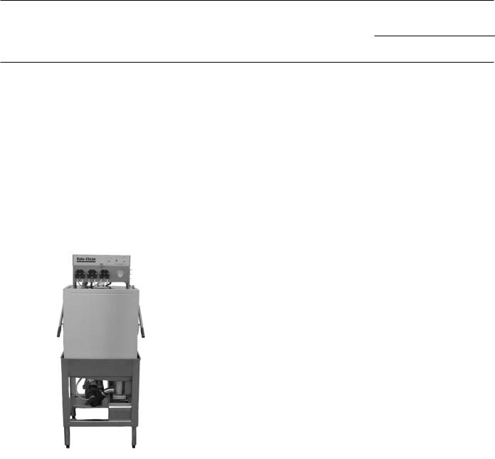
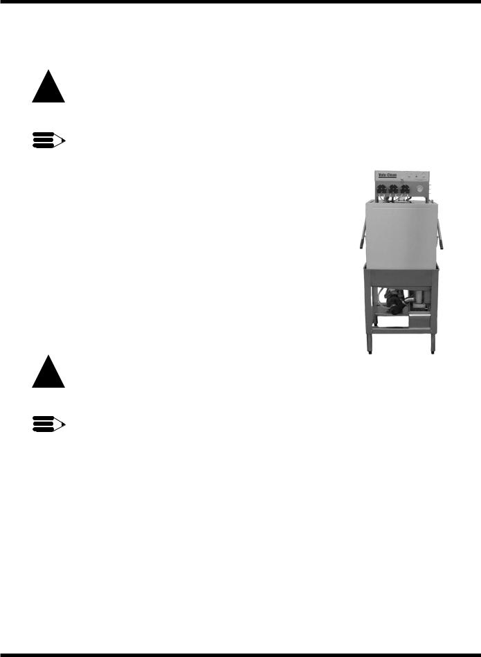
Model
The VC1000 model is a low temperature (140˚F/60˚C ) sanitizing model for use with a hypochlorite (Chlorine) based sanitizer at a minimum concentration of 50PPM or to your local codes, in the final rinse. The dishwasher includes three chemical dispenser pumps located in the control cabinet on the top of the machine.
Standard Equipment
• |
Automatic Operation |
• |
Door safety switch |
• |
Common utility connections |
• Field convertible to corner model |
|
• Balanced door lift system |
• De-lime switch in control cabinet |
||
• Interchangeable upper and lower |
• |
1-hp drip-proof pump motor |
|
|
spray arms |
|
|
1
INSTALLATION
Unpack the dishwasher
!CAUTION:
Care should be taken when lifting the machine to prevent damage.
NOTE:
The installation of your machine must meet all applicable health and safety codes.
1.Immediately after unpacking the machine, inspect for any shipping damage. If damage is found, save the packing material and contact the carrier immediately.
2.Remove the dishwasher from the skid. Move the machine to its permanent location.
3.Machine must be placed on a sound self-draining floor.
4.Level the machine (if required) by placing a level on the top of the machine and adjusting the feet. Level the machine from front-back and side to side.
Electrical Connections
!WARNING:
Electrical grounding connections must comply with all applicable Electrical Codes.
WARNING:
When working on the diswasher, disconnect the electric service and place a tag at the disconnect switch to indicate work is being done on that circuit.
1.A qualified electrician must compare the electrical power supply with the machine electrical specifications before connecting to the incoming service through a fused disconnect switch.
2.The electrical supply is single phase. The machine must be installed on 15A single phase breaker.
3.A knock out is provided at the left rear corner of the control cabinet (as viewed from the front) for electrical service connection or connection will be made from the plug (depending on how the machine was ordered). A fused disconnect switch or circuit breaker (supplied by others) is required to protect the power supply circuit.
4.Single phase incoming wire connections are made at the machine’s main terminal block. The main terminal block is located in the control cabinet on the back wall and to the left side of cabinet.
2
INSTALLATION (CONT.)
Plumbing Connections
NOTE:
Plumbing connections must comply with all applicable sanitary and plumbing codes.
Water Connections
1.VC1000 dishwashers require a single, hot water supply.
2.The hot water connection to the dishwasher is at the 1/2" NPT Female “Y” strainer.
3.The connection is made from the top rear of the dishwasher.
4.The recommended minimum water temperature is 140˚F/60˚C.
5.A manual shut-off valve for water (supplied by others) should be installed in the supply line to allow for servicing of the machine. The shut-off valve should be the same size or larger than the supply line.
6.Install a pressure reducing valve (PRV) in the water supply line if flow pressure exceeds 20-22 PSI/138-151.8kPa.
Drain Connections
1.The dishwasher is a gravity drain machine equipped with 1-1/2" O.D. hose connection point.
2.The maximum drain flow rate is 15 gallons/min-56.8 liters/min.
3.Drain height for the dishwasher must not exceed 11" (280mm) above the floor level.
4.The drain connection is made to the dishwasher by connecting to the tail piece located on the bottom of the drain pan.
Ventilation
NOTE:
Ventilation must comply with local sanitary and plumbing codes.
!CAUTION:
Exhaust air should not be vented into a wall, ceiling, or concealed space of a building. Condensation can cause damage.
3

INSTALLATION (CONT.)
Chemical Pumps
NOTE:
Consult a qualified chemical supplier for your chemical needs.
1. Prime switches are located on the right hand side of the control cabinet.
Peristaltic Pump
To prime the peristaltic pump:
1.Insert pump inlet hose into the detergent container.
2.Close machine door and turn power switch to “ON” position.
3.Allow wash tank to fill up then press detergent pump prime switch to prime inlet and outlet hose.
4.Stop priming when detergent reaches machine.
4
 Loading...