


DH2000

Door-type
High Temperature
Dishwasher
Installation/Operation Manual with Service Replacement Parts
2674 N. Service Road, Jordan Station
Ontario, Canada L0R 1S0
905/562-4195 Fax: 905/562-4618
Toll-free: 800/ 263-5798
3765 Champion Boulevard
Winston-Salem, NC 27105
336/661-1556 Fax: 336/661-1660
Toll-free: 800/ 858-4477
Issue Date: 7.1.14
Manual P/N 114614 rev. L
Printed in the USA
For machines beginning with S/N D09037592 and above
Machine Serial No.
Model: 2000 Series
Hot water sanitizing machine w/fresh
water rinse and built-in stainless steel
electric booster
2000 Series
For Champion Model DH2000 • Moyer Diebel Model MD2000 • International Model IDH2000

COPYRIGHT © 2014 All rights reserved Printed in the USA
For future reference, record your dishwasher information in the box below.
Model Number__________________________ Serial Number_______________________
Voltage________________Hertz_____________ Phase__________________
Service Agent __________________________________ Tel:______________________
Parts Distributor _________________________________ Tel:______________________
ATTENTION:
The model no., serial no., voltage, Hz
and phase are needed to identify your
machine and to answer questions.
The machine data plate is located
on the top-mounted control cabinet.
Please have this information ready
if you call for service assistance.
National Service Department
In Canada: In the USA:
Toll-free: 800/ 263-5798 Toll-free: 800/ 858-4477
Tel: 905/ 562-4195 Tel: 336/ 661-1556
Fax: 905/ 562-4618 Fax: 336/ 661-1660
email: service@moyerdiebellimited.com email: service@championindustries.com
The USGBC and the CaGBC Member Logos are trademarks owned by the U.S. Green Building Council and The Canadian Green Building Council,
respectively, and are used by permission. The logos signify only that Champion Industries and Moyer Diebel are USGBC members and CaGBC
members; USGBC and CaGBC do not review, certify nor endorse the products or services offered by its members.

http://www.championindustries.com/canada/register
REGISTER YOUR PRODUCT ONLINE
Make sure you are connected to the internet then enter the address below.
In the U.S.A
In Canada
http://www.championindustries.com/register
PRODUCT REGISTRATION
BY FAX
(336) 661-1660 in the USA
1-(800) 204-0109 in Canada
IMPORTANT IMPORTANT
Model
Serial #
Date of Installation:
Company Name:
Telephone #: ( ) ---
Contact:
Address:
Address:
Telephone #:
Contact:
Installation Company:
(Street) Province Postal Code
FAILURE TO REGISTER YOUR PRODUCT MAY VOID YOUR WARRANTY
PRODUCT REGISTRATION CARD
COMPLETE THIS FORM AND FAX TO:

i
Revision History
Revision Revised Serial Number Revision
Date Pages Effectivity Description
6.12.09 All D09037592 Released First Edition
Revision History
The Revision History can contain part number changes, new instructions, or information that was
not available at print time. We reserve the right to make changes to these instructions without
notice and without incurring any liability by making the changes. Equipment owners may request
a revised manual, at no charge, by calling 1 (800) 858-4477 in the USA or by calling
1 (800) 263-5798 in Canada.
8.12.09 All D09037592 Changed Schematic for
Overlow tempering Ckt.
9.11.09 24-25 D09087829 Added 1/2" Piping to Fill Assy.
9.16.09 31-32 D09087829 Corrected P/N of Pump Suction
Screen to 333021
10.23.09 20-21 D09087829 Added 1/2" to Booster Piping
2.12.10 26-27 D09087829 Added Front and Side Panels
2.22.10 5 D09087829 Changed location of element
jumper bars
10.6.10 31 D09087829 Changed description of items
22, 23, 24
3.8.11 24-25 All Added P/N 114861, Endcap
Item 37 to parts list
8.22.11 30-31 D10088521 Changed Item 2, P/N 114468 to
P/N 114745
6.1.12 36 D10088521 Revised Electrical Schematic
Drain Tempering Circuit
6.1.12 24-25 All Use Kit 900962 to repair or
replacethenalrinsearm
12.16.13 22-23 D130711000 Updated control cabinet cover
to square corners, P/N 335089
7.1.14 30-31 All Float Switch Flat washer P/N
changed to 104882

ii
Limited Warranty
LIMITED WARRANTY
Champion Industries Inc. (herein referred to as Champion), 3765 Champion Blvd., Winston-Salem, North Carolina 27105,
and P.O. Box 301, 2674 N. Service Road, Jordan Station, Canada, L0R 1S0, warrants machines, and parts,
as set out below.
Warranty of Machines: Champion warrants all new machines of its manufacture bearing the name
"Champion" and installed within the United States and Canada to be free from defects in material and workman
ship for a period of one (1) year after the date of installation or fteen (15) months after the date of shipment by
Champion, whichever occurs rst. [See below for special provisions relating to glasswashers.] The warranty
registration card must be returned to Champion within ten (10) days after installation. If warranty card is not
returned to Champion within such period, the warranty will expire after one year from the date of shipment.
Champion will not assume any responsibility for extra costs for installation in any area where there are
jurisdictional problems with local trades or unions.
If a defect in workmanship or material is found to exist within the warranty period, Champion, at its election,
will either repair or replace the defective machine or accept return of the machine for full credit; provided;
however, as to glasswashers, Champion's obligation with respect to labor associated with any repairs shall end
(a) 120 days after shipment, or (b) 90 days after installation, whichever occurs rst. In the event that Champion
elects to repair, the labor and work to be performed in connection with the warranty shall be done during regular
working hours by a Champion authorized service technician. Defective parts become the property of Champion.
Use of replacement parts not authorized by Champion will relieve Champion of all further liability in connection
with its warranty. In no event will Champion's warranty obligation exceed Champion's charge for the machine.
The following are not covered by Champion's warranty:
a. Lighting of gas pilots or burners.
b. Cleaning of gas lines.
c. Replacement of fuses or resetting of overload breakers.
d. Adjustment of thermostats.
e. Adjustment of clutches.
f. Opening or closing of utility supply valves or switching of electrical supply current.
g. Cleaning of valves, strainers, screens, nozzles, or spray pipes.
h. Performance of regular maintenance and cleaning as outlined in operator’s guide.
i. Damages resulting from water conditions, accidents, alterations, improper use, abuse,
tampering, improper installation, or failure to follow maintenance and operation procedures.
j. Wear on Pulper cutter blocks, pulse vanes, and auger brush.
Examples of the defects not covered by warranty include, but are not limited to: (1) Damage to the exterior or
interior nish as a result of the above, (2) Use with utility service other than that designated on the rating plate,
(3) Improper connection to utility service, (4) Inadequate or excessive water pressure, (5) Corrosion from
chemicals dispensed in excess of recommended concentrations, (6) Failure of electrical components due to
connection of chemical dispensing equipment installed by others, (7) Leaks or damage resulting from such
leaks caused by the installer, including those at machine table connections or by connection of chemical
dispensing equipment installed by others, (8) Failure to comply with local building codes, (9) Damage
caused by labor dispute.
Warranty of Parts: Champion warrants all new machine parts produced or authorized by Champion to be free
from defects in material and workmanship for a period of 90 days from date of invoice. If any defect in
material and workmanship is found to exist within the warranty period Champion will replace the defective
part without charge.
DISCLAIMER OF WARRANTIES AND LIMITATIONS OF LIABILITY. CHAMPION'S WARRANTY IS ONLY TO THE EX-
TENT REFLECTED ABOVE. CHAMPION MAKES NO OTHER WARRANTIES, EXPRESS OR IMPLIED, INCLUDING,
BUT NOT LIMITED, TO ANY WARRANTY OF MERCHANTABILITY, OR FITNESS OF PURPOSE. CHAMPION SHALL
NOT BE LIABLE FOR INCIDENTAL OR CONSEQUENTIAL DAMAGES. THE REMEDIES SET OUT ABOVE ARE
THE EXCLUSIVE REMEDIES FOR ANY DEFECTS FOUND TO EXIST IN CHAMPION DISHWASHING MACHINES AND
CHAMPION PARTS, AND ALL OTHER REMEDIES ARE EXCLUDED, INCLUDING ANY LIABILITY FOR INCIDENTALS
OR CONSEQUENTIAL DAMAGES.
Champion does not authorize any other person, including persons who deal in Champion dishwashing machines
to change this warranty or create any other obligation in connection with Champion Dishwashing Machines.

iii
Revision History ...........................................................................................................i
Limited Warranty ...........................................................................................................ii
Model Descriptions ...........................................................................................................iv
Installation ..............................................................................................1
Receiving ....................................................................1
Electrical Connections ................................................2
1 phase to 3 phase Conversion ......................5
Hot Water and Drain Connections ..............................6
Vent Fan and Chemical Dispensers ...........................7
Initial Start-up ..........................................................................................7
Installation Check List .................................................8
Operation ................................................................................................................9
Normal Wash Mode ....................................................9
Rinse Sentry Mode .....................................................11
Automatic Drain Cycle ................................................11
Cleaning and Maintenance ........................................................................12
Cleaning ......................................................................12
De-liming .....................................................................14
Maintenance ...............................................................15
Troubleshooting ..........................................................16
Service Replacement Parts .......................................................................17
Timer Chart
.............................................................................................35
Electrical Schematic..............................................................................................36
Table of Contents
Table of Contents
2000 Series Door-type Dishwasher

iv
Model Description
Model Description
2000 Series
High temperature hot water sanitizing dishwasher with
built-in 40-70°F/22-82°C rise booster heater.
Field convertible single or three phase
Self-draining pump
Automatic start
Fresh water rinse
55 racks per hour/60-second total cycle time
Rinse sentry
Automatic drain valve
Optional Equipment
(consult factory)
Drain water tempering kit
Side panels
1
NOTE:
The installation of your dishwasher must be performed by qualified service personnel.
Problems due to improper installation are not covered by the Warranty.
1. Inspect the outside of the dishwasher carton for signs of damage.
2. Remove the carton and inspect the dishwasher for damage.
3. Check for any accessories that may have shipped with your dishwasher.
4. Turn to the front of this manual and complete the warranty card.
Immediately mail the warranty card to validate your warranty.
5. Move the dishwasher near its permanent location.
CAUTION:
Be careful when lifting and moving the dishwasher to prevent damage to the machine.
NOTE:
The installation of the dishwasher must comply with all local electrical, plumbing, health and
safety codes or in the absence of local codes, installed in accordance with the applicable
requirements in the National Electrical Code, NFPA 70, Canadian Electrical Code (CEC),
Part 1, CSA C22.1; and the Standard for Ventilation Control and Fire Protection of
Commercial Cooking Operations, NFPA 96.
6. Compare the installation site utility connections with the dishwasher utility connections and
make sure that they are the same.
7. Place the dishwasher in its permanent location.
8. The dishwasher has 4 adjustable feet for leveling.
9. Level the dishwasher front-to-back and
side-to-side.
10. The dishwasher can be installed in a
straight-through or a corner conguration.
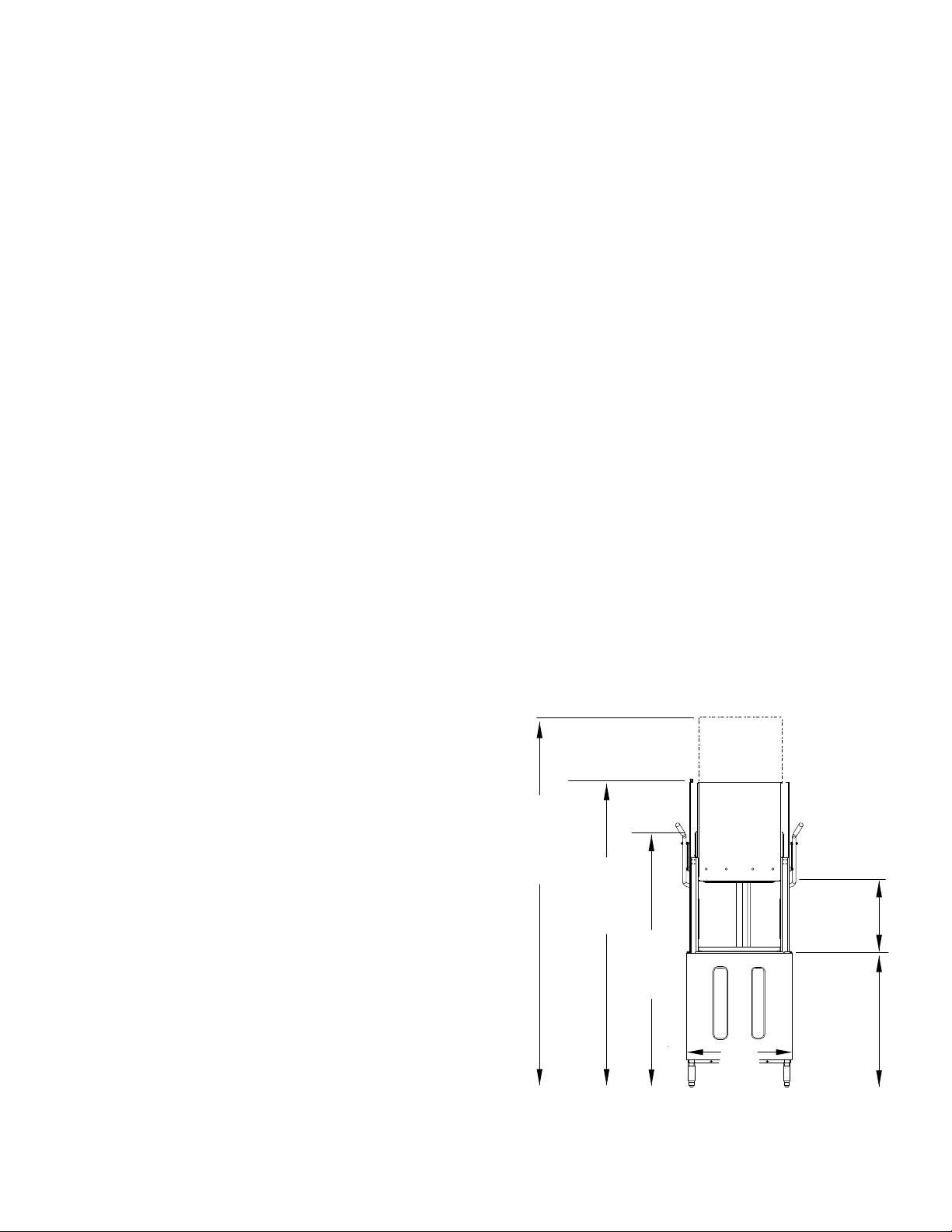
11. The typical dishwasher load height is
33¾" [86cm].
12. The machine height is 65¼" [166cm].
13. The dishwasher doors require an
open height of 76¾" [195cm] and
86" [218cm] for door removal.
Installation
Receiving
17¼"
[44cm]
33¾"
[86cm]
76¾"
[195cm]
65¼"
[166cm]
26⅛"
[66cm]
Load
Ht.
Machine
Ht.
Door Up
Ht.
86"
[218cm]
Door
Removal
Ht.
Inside
Clearance
Dishwasher Dimensions in inches and Centimeters
2
Installation
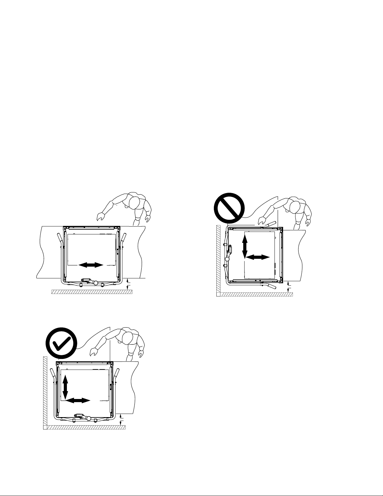
Converting Straight-through Operation to Corner Operation
Dishwashers are shipped from the factory for Straight-through operation. Refer to the diagrams below
and on the next page to convert a Straight-through operation machine to a Corner operation machine.
Dish racks enter and exit the sides of a straight-through machine. Dish racks enter the side and exit the
front of corner operation machine.
To convert the dishwasher:
1. Convert the dishwasher before it is placed in its nal position and before connecting utilities.
2. The temperature gauges must be clearly visible to the operator when facing the front of the
machine. In addition, the door handles should move freely without interference from walls or other
obstructions. Nominal wall clearance is 6" [152mm]; the minimum wall clearance is 4" [102mm].
3. Position the dishwasher as shown below and refer to the next page for instructions on changing
the dish rack guides and door operation.
6" [15cm]
Temp.
Gauges
Correct Orientation for
Corner Operation
6" [15cm]
Temp.
Gauges
Incorrect Orientation for
Corner Operation
6" [15cm]
Temp.
Gauges
Correct Orientation for
Straight-Through Operation

3
Installation
Converting Straight-through Operation to Corner Operation
wall
wall
A
A
To convert track guides and door-lift for corner operation:
1. Remove the rack guide (A); save the fasteners.
Move (A) and re-attach as shown in the illustration at right.
2. Slide a dish rack through the machine to check the guide to
dish rack clearance. The dish rack should move smoothly
without binding or tipping on the guides.
3. Disconnect the door-lift bracket (B) connecting the front door
and the wall-side door and discard. To seal the holes,
Re-install the bolts and lockwashers that held the bracket.
4. Disconnect the door linkage arm (C) from the wall-side door
and discard. Re-install the white roller (D) and hardware.
5. Disconnect the door linkage arm (C) from the other door but
do not discard.
6. Lift the door handle up and back until the springs relax.
7. Adjust the door spring hooks (E) located at the rear of
dishwasher to reduce door spring tension until the front and
side doors open and close without binding.
B
Remove the door-lift
bracket connecting the
front and wall-side
doors.
E
Re-adjust the door springs at the rear of the
dishwasher then check that the doors open
and close without binding.
Remove the door-linkage
arm from the wall-side
door and discard.
Re-install the white roller
with existing hardware.
C
D
4
Installation
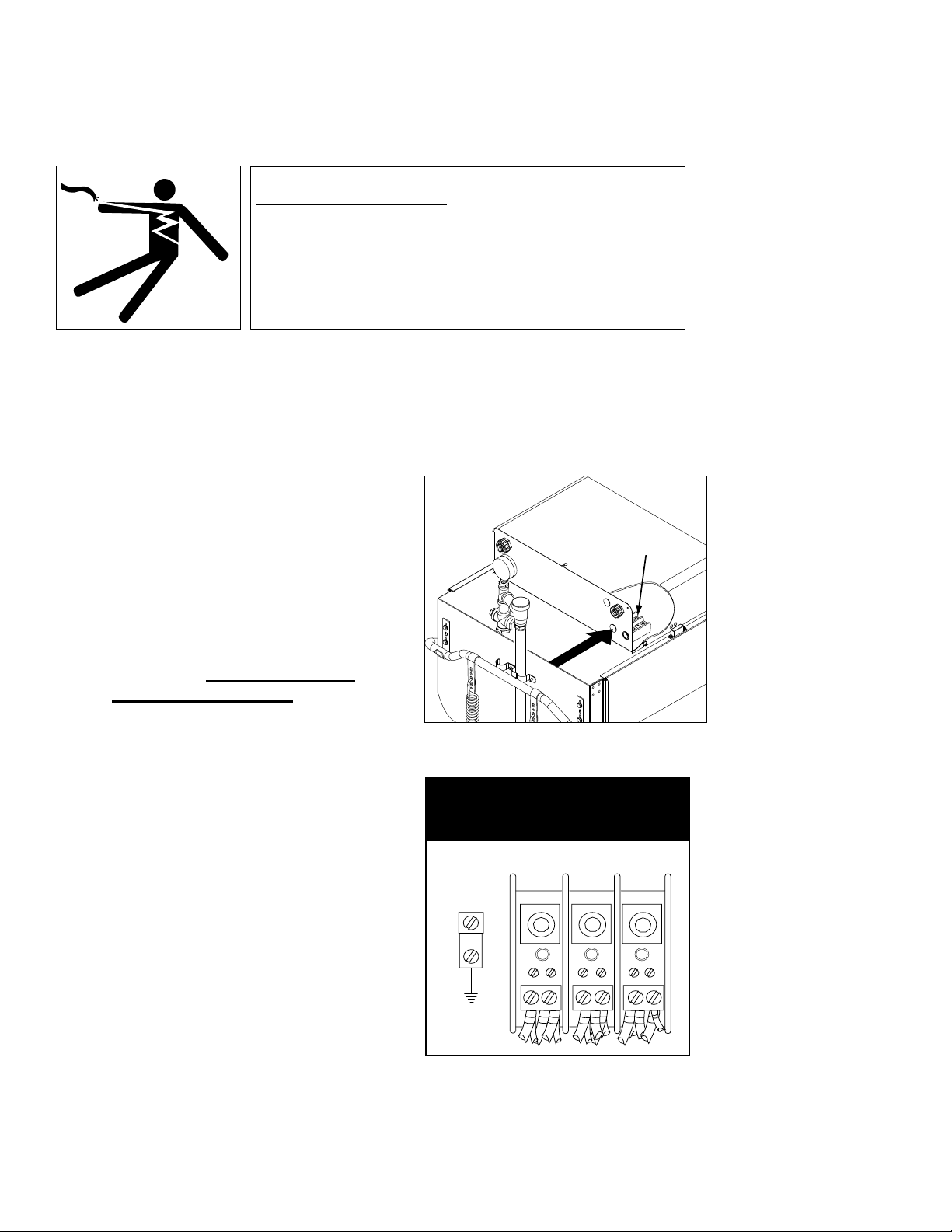
Electrical Connections
ATTENTION
A qualified electrician must connect the main incoming power to the dishwasher in accordance with all
local codes and regulations or in the absence of local codes in accordance with the National Electrical
Code.
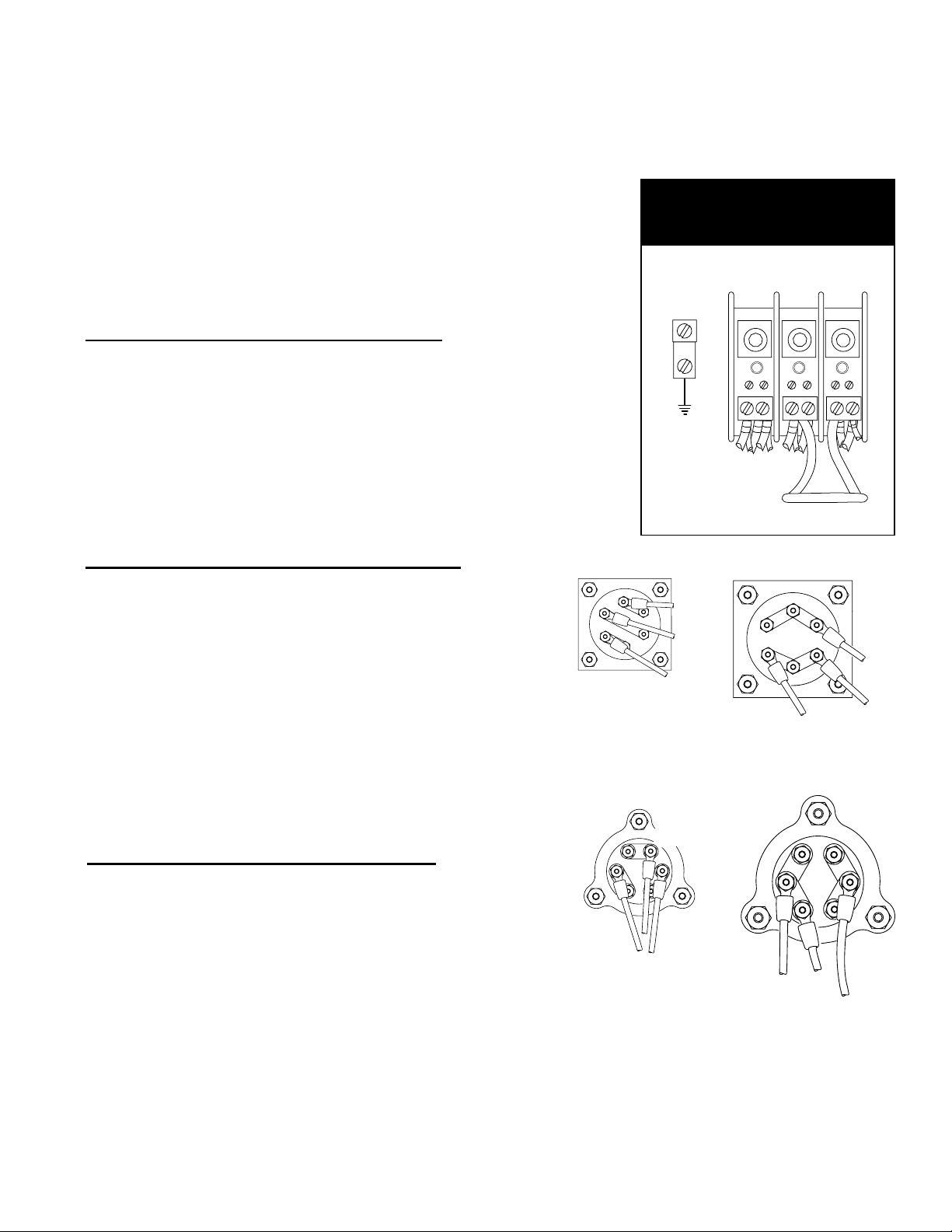
THREE PHASE
POWER CONNECTION
208-240V/60/3
LINE IN
L1 L2 L3
GRD
Standard Dishwashers are shipped from
the factory for 3-phase operation.
To connect the dishwasher for 3-phase
operation:
1. Remove the top-mounted control
cabinet cover and locate the main
terminal block in the left-rear
corner of the cabinet.
2. Refer to the Machine Electrical
Connection Data Plate located
near the main terminal block and
make sure that the incoming
power supply matches the
machine's electrical requirements.
3. Connect the incoming 3-phase
power as shown in the illustration
to the right.
4. Re-install the control cabinet
cover.
WARNING:
Electrocution or serious injury may result when working on an
energized circuit.
Disconnect power at the main breaker or service disconnect
switch before working on the circuit.
Lock-out and tag the breaker to indicate that work is being
performed on the circuit.
Three Phase Operation
Main Terminal Block
Main Terminal Block Location
NOTE:
Refer to the next page for 3-phase to
1-phase field conversion instructions.
5
A standard 3-phase operation dishwasher can be converted for
1-phase operation with the installation of a jumper wire on the main
terminal and rewiring of the wash tank and booster tank heaters.
A jumper wire, jumper bars and a new data plate are stowed
on top of the wash tank heater junction box.
To convert the dishwasher from 3-phase to 1-phase operation:
Install Main Terminal Block Jumper Wire
1. Disconnect all power to the machine.
2. Remove the top-mounted control cabinet cover and locate the
main terminal block located in the left-rear corner of the cabinet.
3. Connect the jumper wire (shipped inside the control cabinet)
between L2 and L3 on the output side of the main terminal block.
4. Connect the 1-phase incoming power supply to L1 and L2 on the
input side of the main terminal block.
Rewire Wash Tank Heater Element for 1PH
1. Remove the lower front panel.
2. Remove the wash tank heater junction box cover.
3. Remove the paper insulator and jumper bars from the heater
terminals.
4. Additional short jumper bars are stowed with the new data plate.
5. Reposition the jumper bars for 1PH as shown below.
6. Connect the #33 wire to one element terminal as shown.
7. Connect the #34 and #35 wires to the other terminals as shown.
8. Reinstall the paper insulator and the junction box cover.
Rewire Booster Heater Element for 1PH
1. Remove the booster heater element cover.
2. Remove the paper insulator and jumper bars from the heater
terminals.
3. Install the jumper bars for 1PH as shown below.
4. Additional short jumper bars are stowed with the new data plate.
5. Connect the #36 wire to one element terminal as shown.
6. Connect the #37 and #38 wires to the other terminals as shown.
7. Reinstall the paper insulator and the booster heater element cover.
Installation
Electrical Connections
Connect the jumper wire between L2 and L3
on the output side of the main terminal block
SINGLE PHASE
POWER CONNECTION
208-240V/60/1
LINE IN
GRD
L1 L2
L1 L2 L3
JUMPER
Field Conversion from 3-phase to 1-phase Operation
3PH
33
34
35
L3
L2
L1
36
37
38
3PH
L3
L2
L1
NOTE: The additional jumper bars needed
for 1PH operation are stowed with the new
data plate on top of the wash tank heater
junction box.
33
34
35
1PH
L3
L2
L1
36
37
38
1PH
L3
L2
L1
ATTENTION:
Affix the new data plate on top of the existing machine data plate to complete the conversion.
6
Installation
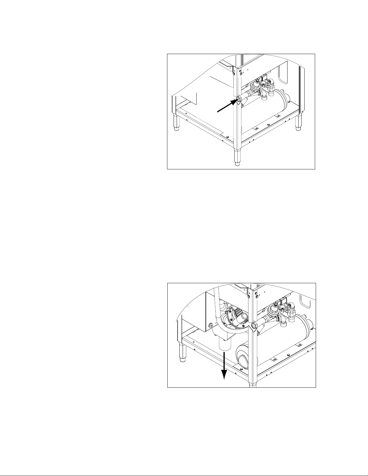
Hot Water Connection
NOTE:
Plumbing connections must comply with all national and/or local plumbing and sanitary codes.
The hot water connection is located at the lower
left-rear side of the dishwasher. A 3/4" line
strainer and pressure regulating valve (PRV)
were installed at the factory.
1. The size of the incoming hot water line
should be 3/4" or larger.
2. The PRV should be adjusted to supply a
minimum owing pressure of 20 PSI/138
kPA during the nal rinse. The maximum
owing pressure must not exceed 25
PSI/172 kPa during the nal rinse.
3. The temperature of the incoming
hot water must maintain a minimum
temperature of 140°F/60°C for a
40°F/22°C rise booster or a minimum
temperature of 110°F/43°C for a
70°F/39°C rise booster.
4. A manually operated 3/4" or larger
shut-off valve should be installed in the
incoming line as close to the dishwasher
as possible for servicing.
Drain Connection
The incoming hot water line is a 3/4" NPT connection.
The drain water connection is a 2" slip-fit hose
connection and is located at the center-rear of
the machine base. It is a gravity drain.
1. The dishwasher drain is 2" O.D. hose
connection.
2. A optional drain water tempering kit
is available (consult the factory).
3. Drain water ow is controlled by an
automatic electrically operated drain
valve.
4. The oor sink and/or drain plumbing
must be able to accommodate a
maximum drain ow rate of
20 US gpm / 17 Imp gpm / 76 Lpm.
The drain is a 2" slip-fit hose connection.
 Loading...