


U-BW
The Dishwashing Machine Specialists
Champion
®
Undercounter
Dishwasher
Model
TUW
U-BW
UTL
August, 2001
P.O. Box 4149
Winston-Salem, North Carolina 27115-4149
Champion Industries, Inc. 336/661-1556 Fax: 336/661-1660
Manual P/N 0508812 REV. H
Machine Serial No.
Technical Manual

Complete the information below so it will be available for quick reference.
Model Number __________________________ Serial Number ________________________
Voltage and Phase ______________________________________________________________
Champion Parts Distributor __________________________________ Phone _____________
(if applicable)
_____________________________________________________________________________
Champion Service Agency___________________________________ Phone _____________
_____________________________________________________________________________
Champion Industries Service: 1-800-858-4477 Champion Service Fax: 1-336-661-1660
NOTE: When calling to order parts, be sure to have the model number, serial number, voltage,
and phase of your machine.
COPYRIGHT © 2001 by Champion Industries

REVISIONS
Revision History
Revision Revised Serial Number Comments
Date Pages Effectivity
4/10/00 All — Added Models U-BW and UTL to manual and parts list.
11/16/00 38-39 — Deleted P/N 112204 thermostat, replaced with
P/N 109069 for all serial numbers.
1/17/01 17 — Revised front panel number to 0308741.
8/22/01 21 — Revised part numbers for hose clamps and hose.

CONTENTS
CONTENTS
Page
INTRODUCTION....................................................................................................................................... 1
WARRANTY .............................................................................................................................................. 2
GENERAL .................................................................................................................................................. 3
INSTALLATION ........................................................................................................................................ 5
Unpacking ............................................................................................................................................ 5
Electrical Connections.......................................................................................................................... 5
Plumbing Connections ......................................................................................................................... 6
Detergent .............................................................................................................................................. 6
Rinse-Aid ............................................................................................................................................. 6
Chemical Sanitizer ............................................................................................................................... 6
Completing Installation ........................................................................................................................ 7
OPERATION .............................................................................................................................................. 8
Operation Summary ............................................................................................................................. 8
Operation Procedures ........................................................................................................................... 8
Extended Wash Cycle .......................................................................................................................... 9
MAINTENANCE........................................................................................................................................ 10
Cleaning Schedule................................................................................................................................ 10
Deliming............................................................................................................................................... 11
Deliming Process.................................................................................................................................. 11
Maintenance Schedule.......................................................................................................................... 12
TROUBLESHOOTING .............................................................................................................................. 13
REPLACEMENT PARTS........................................................................................................................... 15
ELECTRICAL DIAGRAMS ...................................................................................................................... 42
TIMER CHARTS and DIAGRAMS........................................................................................................... 46
LIST OF FIGURES
Figure 1—Track and Panel Assembly......................................................................................................... 16
Figure 2—Door and Switch Assembly........................................................................................................ 18
Figure 3—Tank Heat and Drain .................................................................................................................. 20
Figure 4—Pump Assembly ......................................................................................................................... 22
Figure 5—Wash System Assembly............................................................................................................. 24
Figure 6—Water Inlet Piping ...................................................................................................................... 26
Figure 7—Fill System ................................................................................................................................. 28
Figure 8—Booster Assembly ...................................................................................................................... 30

CONTENTS
Figure 9—Detergent Pump Assembly....................................................................................................... 32
Figure 10—Sanitizer/Rinse-Aid Pump Assembly....................................................................................... 34
Figure 11—Drain Pump Assembly ............................................................................................................. 36
Figure 12—Control Cabinet ........................................................................................................................ 38
Figure 13—Electrical Diagram, TUW (For machines beginning with S/N 6984)...................................... 42
Figure 14—Electrical Diagram, U-BW (For machines beginning with S/N 6984) .................................... 43
Figure 15—Electrical Diagram, UTL (For machines beginning with S/N 6984)....................................... 44
Figure 16—Electrical Diagram, TUW (50Hz)............................................................................................ 45
Figure 17—Electrical Diagram, TUW (For machines built prior to S/N 6984) ......................................... 46
Figure 18—Timer Chart and Diagram, TUW, U-BW ................................................................................ 47
Figure 19—Timer Chart and Diagram, UTL .............................................................................................. 48

1
INTRODUCTION
INTRODUCTION
Welcome to Champion.
Thank you for choosing Champion and for allowing us to take care of your dishwashing needs.
This manual covers several models. Model numbers are shown on the front cover.
Your machine has been completely assembled, inspected, and thoroughly tested at our factory to
eliminate problems at installation before it was shipped to your installation site. This manual
provides:
• Warranty information
• Installation and operation procedures
• Maintenance instructions
• Troubleshooting guide
• Replacement parts lists.
Complete and return your warranty registration card as soon as possible.
Champion constantly improves its products; therefore, specifications contained in this manual
may have changed.
For your protection, factory authorized parts should always be used.
Replacement parts may be ordered directly from Champion or from your Champion authorized
parts distributor or service agency.* When ordering parts, supply the model number, serial
number, voltage and phase of your machine, the part number, part description, and quantity.
*Champion can only ship parts to customers with accounts or by C.O.D.

2
WARRANTY
LIMITED WARRANTY
Champion Industries/Moyer Diebel Limited, P.O. Box 4183, Winston-Salem, North Carolina 27115, and P. O. Box 301, 2674
North Service Road, Jordan Station, Ontario, Canada L0R 1S0 warrants machines, and parts, as set out below.
Warranty of Machines: Champion Industries/Moyer Diebel Limited warrants all new machines of its manufacture bearing
the name “Champion” or "Moyer Diebel" and installed within the United States and Canada to be free from defects in
material and workmanship for a period of one (1) year after the date of installation or fifteen (15) months after the date of
shipment by Champion/Moyer Diebel, whichever occurs first. [See below for special provisions relating to Model Series DF
and SW.] The warranty registration card must be returned to Champion/Moyer Diebel within ten (10) days after installation.
If warranty card is not returned to Champion/Moyer Diebel within such period, the warranty will expire after one year from
the date of shipment.
Champion/Moyer Diebel will not assume any responsibility for extra costs for installation in any area where there are
jurisdictional problems with local trades or unions.
If a defect in workmanship or material is found to exist within the warranty period, Champion/Moyer Diebel, at its election,
will either repair or replace the defective machine or accept return of the machine for full credit; provided, however, as to
Model Series DF and SW, Champion/Moyer Diebel's obligation with respect to labor associated with any repairs shall end
(a) 120 days after shipment, or (b) 90 days after installation, whichever occurs first. In the event that Champion/Moyer
Diebel elects to repair, the labor and work to be performed in connection with the warranty shall be done during regular
working hours by a Champion/Moyer Diebel authorized service technician. Defective parts become the property of
Champion/Moyer Diebel. Use of replacement parts not authorized by Champion/Moyer Diebel will relieve Champion/
Moyer Diebel of all further liability in connection with its warranty. In no event will Champion/Moyer Diebel's warranty
obligation exceed Champion/Moyer Diebel's charge for the machine. The following are not covered by Champion/Moyer
Diebel's warranty:
a. Lighting of gas pilots or burners.
b. Cleaning of gas lines.
c. Replacement of fuses or resetting of overload breakers.
d. Adjustment of thermostats.
e. Adjustment of clutches.
f. Opening or closing of utility supply valves or switching of electrical supply current.
g. Adjustments to chemical dispensing equipment.
h. Cleaning of valves, strainers, screens, nozzles, or spray pipes.
i. Performance of regular maintenance and cleaning as outlined in operator’s guide.
j. Damages resulting from water conditions, accidents, alterations, improper use, abuse,
tampering, improper installation, or failure to follow maintenance and operation procedures.
Examples of the defects not covered by warranty include, but are not limited to: (1) Damage to the exterior or interior finish
as a result of the above, (2) Use with utility service other than that designated on the rating plate, (3) Improper connection to
utility service, (4) Inadequate or excessive water pressure, (5) Corrosion from chemicals dispensed in excess of recommended concentrations, (6) Failure of electrical components due to connection of chemical dispensing equipment installed
by others, (7) Leaks or damage resulting from such leaks caused by the installer, including those at machine table connections or by connection of chemical dispensing equipment installed by others, (8) Failure to comply with local building
codes, (9) Damage caused by labor dispute.
Warranty of Parts: Champion/Moyer Diebel warrants all new machine parts produced or authorized by Champion/Moyer
Diebel to be free from defects in material and workmanship for a period of 90 days from date of invoice. If any defect in
material and workmanship is found to exist within the warranty period Champion/Moyer Diebel will replace the defective
part without charge.
DISCLAIMER OF WARRANTIES AND LIMITATIONS OF LIABILITY. CHAMPION/MOYER DIEBEL'S
WARRANTY IS ONLY TO THE EXTENT REFLECTED ABOVE. CHAMPION/MOYER DIEBEL MAKES NO
OTHER WARRANTIES, EXPRESS OR IMPLIED, INCLUDING, BUT NOT LIMITED TO, ANY WARRANTY OF
MERCHANTABILITY, OR FITNESS OF PURPOSE. CHAMPION/MOYER DIEBEL SHALL NOT BE LIABLE
FOR INCIDENTAL OR CONSEQUENTIAL DAMAGES. THE REMEDIES SET OUT ABOVE ARE THE EXCLUSIVE REMEDIES FOR ANY DEFECTS FOUND TO EXIST IN CHAMPION/MOYER DIEBEL DISHWASHING
MACHINES AND CHAMPION/MOYER DIEBEL PARTS, AND ALL OTHER REMEDIES ARE EXCLUDED,
INCLUDING ANY LIABILITY FOR INCIDENTALS OR CONSEQUENTIAL DAMAGES.
Champion/Moyer Diebel does not authorize any other person, including persons who deal in Champion/Moyer Diebel
dishwashing machines, to change this warranty or create any other obligation in connection with Champion/Moyer Diebel
Dishwashing Machines.
rev. 8699

3
GENERAL
GENERAL
This manual covers the Champion undercounter dishwashing machine. This machine is fully
automatic and is equipped with a 1/2 H.P. pump motor. All models are available for mounting
directly to the floor or on optional stands (see accessories listed on page 4).
Standard equipment includes:
-Automatic tank fill -Upper and lower wash/rinse arms
-Common utility connections -Two dish racks (peg and flat)
-120 Volt control circuit -Exclusive vent design for
-Convenient, easy to use controls venting of condensation
-Door latch activated start switch -Stainless steel heavy-gauge construction,
-Detergent pump including base
This series of dishwashers is available in the following models:
Model Numbers
TUW, U-BW, UTL
• The TUW model is a high temperature (82°C/180°F rinse) sanitizing model with booster.
• The U-BW model is a high temperature (82°C/180°F rinse) sanitizing model without
booster.
• The UTL model is a low temperature (60°C/140°F rinse) sanitizing model for use with
5.25% or 8.4% sodium hypochlorite solution (chlorine bleach) as a sanitizing agent. The
rinse aid pump is optional.
Options
• Kit 504 - Top and side panels (P/N 0708756)
• Kit 505 - Top panel only (P/N 0708744)
• Kit 506 - Left side panel only (P/N 0708745)
• Kit 507 - Right side panel only (P/N 0708746)
• Kit 508 - Rinse aid pump kit (P/N 0708754)
• Kit 510 - Extended reach pumped drain kit (TUW, U-BW, UTL) (P/N 0708766)
• Kit 511 - 30°C/70°F temperature rise booster (for 49°C/110°F supply water).
4
GENERAL
Accessories
• 17RS - 17" rack stand (raises working height and adds rack storage)
• 17T - 17" cabinet (raises working height and adds storage)
• CST - Combination sink/table (scraping and sorting station)
• 0501653 - Dish Rack (Peg Rack)
• 0501654 - Silverware Rack (Flat Bottom Rack)
Electrical Power Requirements
Booster Machine Power Requirement
Model Voltage Rise Full Load Amp (125% Service Factor)
UTL 115/60/1 N/A 12 15
U-BW 115/60/1 N/A 12 15
TUW 208/60/1 40 36 44
TUW 240/60/1 40 40 49
TUW 208/60/1 70 48 59
TUW 240/60/1 70 55 68
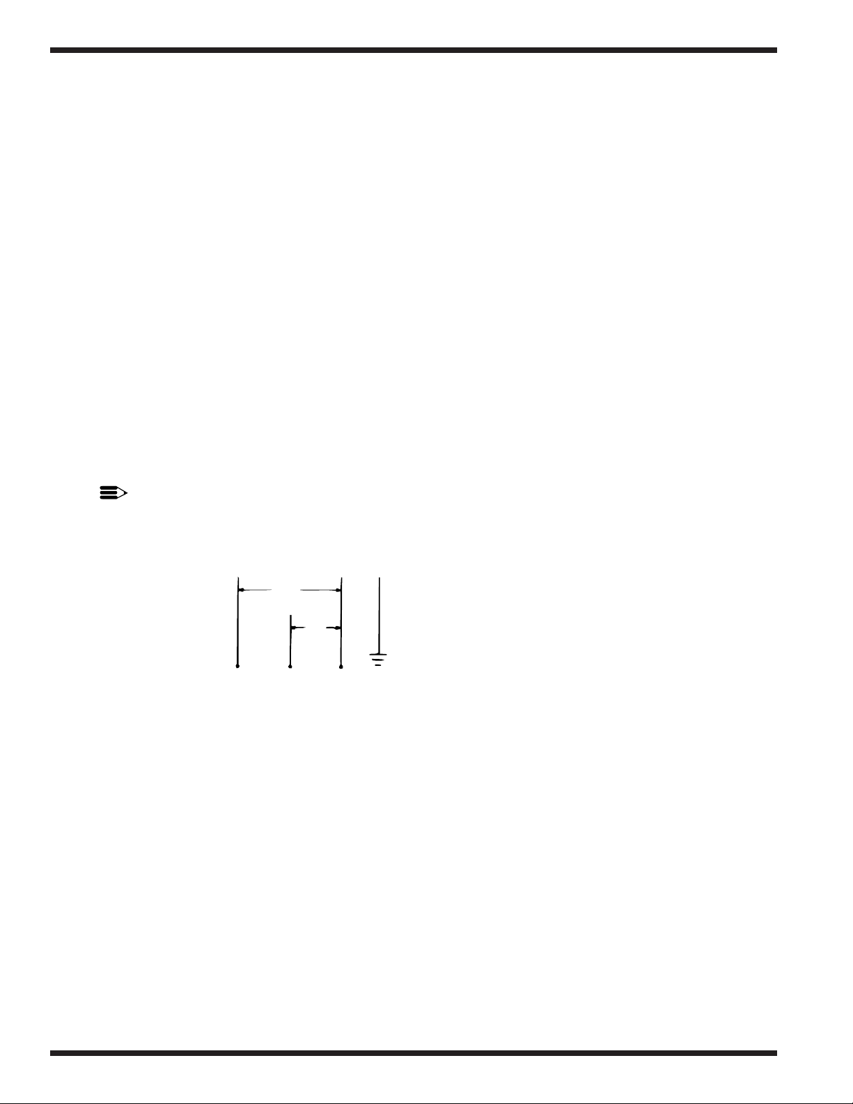
NOTE:
208-240V/60Hz/1PH electrical supply service must be a 3-wire plus ground for connection
as shown.
—3-Wire Plus Ground Diagram
00023
115v
115v
L
1
L
2
NG

5
INSTALLATION
INSTALLATION
Unpacking
WARNING:
Care should be taken when lifting the machine to prevent damage.
1. Immediately after unpacking your machine, inspect for any shipping damage. If damage is
found, save the packing material and contact the carrier immediately.
2. Remove the dishwasher from the skid. Adjust the feet if required, then move the machine to
its permanent location.
3. Level the machine (if required) by placing a level on the top of the machine and adjusting
the feet. Level the machine front-to-back and side-to-side.
CAUTION:
After locating your machine, it must meet local health codes. An example may be to seal
your machine to the floor using a good grade of silicone sealant.
Electrical Connections
WARNING:
Electrical and grounding connections must comply with the National Electrical Code and/or
Local Electrical Codes.
WARNING:
When working on the dishwasher, disconnect the electric service and tag it to indicate work
is being done on that circuit.
1. The electrician should compare the electrical specifications on the machine electrical
junction box (located behind the front panel) to the electrical power supply before
connecting the machine to the incoming service at a fused disconnect switch.
NOTE:
The 208-240V/60Hz/1PH electrical supply service for this machine must be a
3-wire plus ground service.
2. On the 208V-240V models, a knock-out is provided at the rear of the junction box (located
behind the front panel) for electrical service connections. A fused disconnect switch or
circuit breaker (supplied by user) is required to protect each power supply circuit.
3. On 115V models, your machine is already equipped with a 4-foot power cord and plug
suitable for 115V-15A service.
!
!
!
!

INSTALLATION
6
Plumbing Connections
CAUTION:
Plumbing connections must comply with local sanitary and plumbing codes.
Water Connections
1. Connect the hot water supply (60°C/ 140°F Min) to the 1/2" I.D. fill hose. The fill solenoid
valve is equipped with a flow control that will accept water pressures from 172 kPa/25 psi to
665 kPa/95 psi.
2. Install a manual shut-off valve in the water supply line to accommodate servicing the
machine. The shut-off valve should be the same size or larger than the supply line.
3. The fill solenoid valve is equipped with a built-in strainer to protect from particles in the
water supply.
Drain Connections
1. All Models are supplied with a flexible 5/8" I.D. drain hose, which must be connected to a
1-1/2" drain using a wye (Y) fitting.
Detergent
1. Use a qualified detergent/chemical supplier for your detergent, rinse aid, and chemical
sanitizer needs.
2. Your machine is supplied with a detergent dispensing pump that is internally wired and
ready for use. Using a liquid detergent, insert the labeled Detergent pickup tube into the
detergent container. The pickup tube has a strainer on the end to prevent crystallized
chemical from clogging the supply lines.
3. The cycle timer located in the main control cabinet is equipped with adjustable cams for the
chemical dispensing pump(s). The cams control the length of time that the pumps operate.
A qualified person may adjust the cam settings if necessary. Refer to the timer chart
diagram(s) at the end of the manual for timer cam locations and factory time settings.
NOTE:
A nonchlorinated detergent is recommended for your dishwasher.
Rinse Aid
1. An optional rinse aid pump may be supplied for all models. Using a liquid rinse aid, insert
the labeled Rinse Aid pickup tube into the rinse aid container.
Chemical Sanitizer
1. Model UTL is supplied with an internally wired chemical sanitizer dispensing pump. Using
a 5.25% or 8.4% sodium hypochlorite solution, insert the labeled Chemical Sanitizer pickup
tube into the chemical sanitizer container.
2. Contact your chemical supplier for adjustment of the chemical sanitizer.
!

INSTALLATION
7
Completing Installation
1. Remove any foreign material from inside the machine.
2. Center the scrap screen over the sump opening.
3. Prime the booster using the following procedure (if applicable).
CAUTION:
To prime the booster, the following procedure must be followed AFTER the electrical
and plumbing connections have been made.
a. Close the front door.
b. Remove the front panel.
c. Locate the Installation and Service toggle switch on the extreme left side of
the control box.
d. Press the toggle switch down to the Booster Fill position and hold it
approximately 1 minute (or until water can be heard entering the machine).
e. Release the toggle switch to stop the water flow.
f. You have completed the booster priming process.
NOTE:
Push the Installation and Service toggle switch to the UP position.
Electrical power is now supplied to the machine.
WARNING:
Failure to prime the booster may cause damage to the booster elements and other
electrical components and will void the warranty.
4. After plumbing and electrical connections are completed, check the machine for water leaks
by depressing the ON/FILL switch on the front panel, then close and latch the door. This
allows the tank to fill and to complete the rinse cycle. Check for leaks.
5. Open the door and check the water level. The water level should barely cover the scrap
screen.
6. Depress the OFF/DRAIN switch and close and latch the door to drain the tank. This allows
the machine to complete the 100-second wash and drain cycle. Check the drain plumbing
for leaks.
7. Replace the front panel. Installation is now complete.
!
!

8
OPERATION
OPERATION
Operation Summary
The following is a summary of your Undercounter Dishwashing Machine operating cycle:
1. The cycle begins when you depress the front edge of the door latch toward the door.
2. The green cycle lamp lights and the pump starts.
3. The pump runs during the wash cycle for approximately 80 seconds.
4. The pump stops, and the drain is opened.
5. After a 2-3 second pause, the pump drain cycle begins and continues for approximately 30
seconds.
6. After a 2-3 second pause, the fill valve opens, and the pump starts for the rinse cycle.
7. Within approximately 25 seconds, the rinse cycle is complete. The pump stops, the green
cycle lamp turns off, and the cycle is complete.
8. Open the door and remove the rack of clean ware. The door must remain open for 5 seconds
to allow the timer to reset before starting another cycle.
Operation Procedures
The operation of your dishwasher will be more efficient when these procedures are followed:
1. Check that the spray arms and scrap screen are in place.
2. Close the door and depress the front edge of the door latch toward the door. Push the
ON/FILL switch to the ON position. The tank will begin filling with water. This procedure
is followed only when the tank is empty.
3. When the tank is full, check the wash tank temperature gauge. Minimum wash temperatures
are:
• TUW, U-BW – 150°F/66°C.
• UTL – 140°F/60°C.
4. Scrap and preflush all items to be washed, and load the items into the rack. DO NOT
OVERLOAD the rack. Wash only one layer of silverware in a rack.
5. Open the door and insert the rack into the machine.
6. Shut the door, and depress the door latch. This will start the wash cycle. The green cycle
lamp located on the front control panel will light. This lamp will remain on until the entire
wash and rinse cycle is completed.

9
OPERATION
NOTE:
The machine may be stopped at any time by opening the door. When restarted, the cycle
does not start over. It will continue from the point at which it was interrupted.
7. Check the rinse temperature during the final rinse (120 seconds into cycle). The rinse
temperature must be 180°F/82°C minimum for models TUW, U-BW, and 140°F/60°C for
model UTL.
8. The pump will automatically stop and the green cycle light will turn off indicating the cycle
is completed.
9. Open the door and remove the rack.
10. Repeat steps 4-9 for additional cycles. Machine operation is automatic.
11. CLEAN the scrap screen after every meal period. During heavy usage, the scrap screen
should be cleaned more frequently.
CAUTION:
Poor machine performance and/or damage to the machine can occur if the scrap
screen becomes clogged with soil or waste particles.
12. After completing usage for the day, water in the tank should be drained by depressing the
OFF/DRAIN switch and closing and latching the door. This initiates a 100-second wash and
drain cycle that drains the tank.
CAUTION:
DO NOT LEAVE WATER IN THE TANK OVERNIGHT. Water left in the tank
overnight will allow harmful chemicals to deteriorate the tank.
Extended Wash Cycle
On models TUW, U-BW, but not on model UTL, an extended wash cycle is available for pots,
pans and heavily soiled items.
To use the Extended Wash Cycle:
1. Insert the loaded rack into the machine. Close the door and depress the latch. Wait 10
seconds for the detergent to be dispensed automatically.
2. Flip the Extended Wash/Delime Switch to the UP position. The green cycle light will go
out, indicating that the machine is in a continuous wash mode.
3. When your desired wash time has passed, flip the Extended Wash/Delime Switch to the
DOWN position. The green cycle light will come on, indicating a return to the normal wash
mode. The machine will now complete the remaining portion of the automatic cycle.
!
!

10
MAINTENANCE
MAINTENANCE
The efficiency and life of your machine is increased by regularly scheduled preventive
maintenance. A well maintained machine gives better results and service. An investment of a few
minutes of daily maintenance will be worthwhile.
The best maintenance you can provide is to keep your machine clean. Components that are not
regularly cleaned and flushed will clog and become inoperative.
Intervals shown in the following schedules represent an average length of time between necessary
maintenance. Maintenance intervals should be shortened whenever your machine is faced with
abnormal working conditions, hard water, or multiple shift operations.
Cleaning Schedule
• Daily-Every 8 Hours
1. Depress the OFF/DRAIN switch to OFF and close and latch the door to drain the tank.
2. Open the door and remove both the upper and lower spray arms by unscrewing the
knurled fastener holding each spray arm.
3. Remove the scrap screen carefully to keep soil or waste particles from falling into the
sump.
4. Clean inside the tank with clean water. Backflush the scrap screen until it is clean. Do
not strike the screen against solid objects.
5. Clean the wash arms to remove any debris from spray openings. Do not strike the spray
arms against solid objects.
6. Reinstall the scrap screen and spray arms.
7. Leave the door open overnight to allow drying.
8. Report any unusual conditions to your supervisor.
• Meal Periods
1. Clean the scrap screen after every meal period and more frequently during heavy usage.
Do not allow the scrap screen to become clogged with soil or waste particles.

11
MAINTENANCE
Deliming
Your dishwasher should be delimed regularly as required. This will depend on the mineral content
of your water.
Inspect your machine interior for lime deposits. If deliming is required, a deliming agent should
be used for best results.
If you have the chemical sanitizing model (UTL), carefully follow the following procedure before
deliming:
DANGER:
Deliming solution or other acids must not come in contact with household bleach (sodium
hypochlorite) or any chemicals containing chlorine, iodine, bromine, or fluorine. Mixing
will cause hazardous gases to form. Skin contact with deliming solutions can cause severe
irritation and possible chemical burns. Consult your chemical supplier for specific safety
precautions.
1. Remove the sanitizer tube from the container. Place the tube into a container of hot water.
2. Depress and hold the SANITIZER prime switch (located on the front panel) until clear
water enters the tank through the fill air gap.
3. Close the door and depress the door latch. Complete two operating cycles to purge the
machine of all sanitizer.
Deliming Process
Complete the following procedure to delime your machine:
1. Add the delime chemical to wash the tank (per chemical supplier specifications).
2. Close and latch the door.
3. On models TUW and U-BW, depress the EXTENDED WASH/DELIME switch on the
front panel as soon as the cycle starts. On model UTL, proceed to step 5 of this procedure.
NOTE:
The EXTENDED wash/delime switch will operate only during the wash cycle.
When this switch is in the ON position, the machine stays in the wash cycle until the
switch is OFF. After switching to OFF, the machine will finish the cycle.
4. After 2-1/2 to 3 minutes (or as long as required), turn off the EXTENDED WASH/
DELIME switch. The machine will finish a complete cycle.
5. Complete two cycles with the machine empty to purge the machine of all delime chemicals.
6. Deliming is complete.
!
 Loading...