


Champion 44DR, 66DRPW, 70DRFFPW, 80DRHDPW, 54DR Service Manual
...Installation/Operation with Service Replacement Parts
Single Tank Dual Rinse |
44" Model 44DR |
E-series Rack Conveyor
Dishwashers (with swing-out doors)
Models
Single Tank Dual Rinse |
Single Tank Dual Rinse |
Two Tank |
44" with 22" Prewash |
44DR |
64 |
Model 66DRPW |
||
|
66DRPW |
86PW |
|
70DRFFPW |
90FFPW |
|
80DRHDPW |
100HDPW |
|
54DR |
84 |
|
76DRPW |
106PW |
|
80DRFFPW |
110FFPW |
|
90DRHDPW |
120HDPW |
Two Tank 64"
Wash and Power Rinse
Model 64
|
Issue Date: 12.12.16 |
|
|
www.championindustries.com |
Manual P/N 115328 rev. D |
|
|
For machines beginning with S/N RE13077060 and above |
|
||
3765 Champion Boulevard |
2674 N. Service Road, Jordan Station |
Printed in USA |
|
Winston-Salem, NC 27105 |
Ontario, Canada L0R 1S0 |
|
|
|
|||
|
|
||
(336) 661-1556 Fax: (336) 661-1660 |
(905) 562-4195 Fax: (905) 562-4618 |
|
|
Toll-free: 1 (800) 858-4477 |
Toll-free: 1 (800) 263-5798 |
|
|

For future reference, record your dishwasher information in the box below.
Model Number__________________________ Serial Number_______________________
Voltage________________Hertz_____________ Phase__________________
Champion Service Agent __________________________________ Tel:______________________
Champion Parts Distributor _________________________________ Tel:______________________
National Service Department
|
|
|
|
|
|
In Canada: |
In the USA: |
||||
Toll-free: |
1 (800) 263-5798 |
Toll-free: |
1 (800) 858-4477 |
||
Tel: |
(905) 562-4195 |
Tel: |
(336) 661-1556 |
||
Fax: |
(905) 562-4618 |
Fax: |
(336) 661-1660 |
||
email: service@moyerdiebellimited.com |
email: service@championindustries.com |
||||
ATTENTION:
The dishwasher model number, serial number, voltage, hertz and phase
are needed to identify your machine and to answer questions.
Please have this information on-hand if you call for service assistance.
For all models:
The data plate mounts to one side of the top-mounted control cabinet.
COPYRIGHT © 2016 All rights reserved Printed in the USA

REGISTER YOUR PRODUCT ONLINE
Make sure you are connected to the internet then enter an address below:
In the U.S.A.
http://www.championindustries.com/register
In Canada
http://www.championindustries.com/canada/register
PRODUCT REGISTRATION
BY FAX
COMPLETE THIS FORM AND FAX TO:
(336) 661-1660 in the USA
1 (800) 204-0109 in Canada
PRODUCT REGISTRATION CARD |
|
|||
Model |
|
Serial # |
|
|
Date of Installation: |
|
|
|
|
Company Name: |
|
|
|
|
Address: |
(Street) |
State |
Zip or |
|
Telephone #: ( ) |
||||
--- |
or Province |
Postal Code |
||
Contact: |
|
|
|
|
Installation Company: |
|
|
|
|
Address: |
|
|
|
|
Telephone #: |
|
|
|
|
Contact: |
|
|
|
|
FAILURE TO REGISTER YOUR PRODUCT MAY VOID YOUR WARRANTY |
||||
IMPORTANT |
IMPORTANT |
|||

Revision History
Revision History
A revision might be a part number change, new instructions, or information that was not available at print time. We reserve the right to make changes to this manual without notice and without incurring any liability by making the changes. Dishwasher owners may request a revised manual, at no charge, by calling 1 (800) 858-4477 in the USA or 1 (800) 263-5798 in Canada.
Revision |
Revised |
Serial Number |
Description |
Date |
Pages |
Effectivity |
|
9.11.13 |
All |
RE13077060 |
Released First Edition |
7.14.15 |
60-63, 124-129 |
RE150607977 |
Revised images and Parts List for |
|
|
|
Doors and Screens |
7.14.15 |
All |
--- |
Reviewed and Revised Manual |
4.27.16 |
98-99 |
All |
Reversed Items 5 and 8 |
5.19.16 |
33 |
All |
Removed Arc Suppressor, |
|
|
|
P/N 114934, from Control |
|
|
|
Cabinet Assembly |
12.12.16 |
57 |
All |
Changed the Cradle P/N to 415667 |
i
Limited Warranty
LIMITED WARRANTY
Champion Industries Inc. (herein referred to as Champion), 3765 Champion Blvd., Winston-Salem, North Carolina 27105 and 2674 N. Service Road, Jordan Station, Canada, L0R 1S0, warrants machines, and parts, as set out below.
Warranty of Machines: Champion warrants all new machines of its manufacture bearing the name "Champion" and installed within the United States and Canada to be free from defects in material and workmanship for a period of one (1) year after the date of installation or fifteen (15) months after the date of shipment by Champion, whichever occurs first. [See below for special provisions relating to glasswashers.] Warranty registration must be returned to Champion within ten (10) days after installation either online on the Champion Industries website (http://www.championindustries.com/register) in the USA or http://www.championindustries.com/canada/register in Canada or by fax on the form provided at the front of this manual. If warranty registration is not returned to Champion within such period, the warranty will expire after one year from the date of shipment. Champion will not assume any responsibility for extra costs for installation in any area where there are jurisdictional problems with local trades or unions. If a defect in workmanship or material is found to exist within the warranty period, Champion, at its election, will either repair or replace the defective machine or accept return of the machine for full credit; provided; however, as to glasswashers, Champion's obligation with respect to labor associated with any repairs shall end (a) 120 days after shipment, or (b) 90 days after installation, whichever occurs first. In the event that Champion elects to repair, the labor and work to be performed in connection with the warranty shall be done during regular working hours by a Champion authorized service technician. Defective parts become the property of Champion. Use of replacement parts not authorized by Champion will relieve Champion of all further liability in connection with its warranty. In no event will Champion's warranty obligation exceed Champion's charge for the machine. The following are not covered by Champion's warranty:
a.Lighting of gas pilots or burners.
b.Cleaning of gas lines.
c.Replacement of fuses or resetting of overload breakers.
d.Adjustment of thermostats.
e.Adjustment of clutches.
f.Opening or closing of utility supply valves or switching of electrical supply current.
g.Cleaning of valves, strainers, screens, nozzles, or spray pipes.
h.Performance of regular maintenance and cleaning as outlined in operator’s guide.
i.Damages resulting from water conditions, accidents, alterations, improper use, abuse, tampering, improper installation, or failure to follow maintenance and operation procedures.
j.Wear on Pulper cutter blocks, pulse vanes, and auger brush.
Examples of the defects not covered by warranty include, but are not limited to: (1) Damage to the exterior or interior finish as a result of the above, (2) Use with utility service other than that designated on the rating plate, (3) Improper connection to utility service, (4) Inadequate or excessive water pressure, (5) Corrosion from chemicals dispensed in excess of recommended concentrations, (6) Failure of electrical components due to connection of chemical dispensing equipment installed by others, (7)
Leaks or damage resulting from such leaks caused by the installer, including those at machine table connections or by connection of chemical dispensing equipment installed by others, (8) Failure to comply with local building codes, (9) Damage caused by labor dispute.
Warranty of Parts: Champion warrants all new machine parts produced or authorized by Champion to be free from defects in material and workmanship for a period of 90 days from date of invoice. If any defect in
material and workmanship is found to exist within the warranty period Champion will replace the defective part without charge.
DISCLAIMER OF WARRANTIES AND LIMITATIONS OF LIABILITY. CHAMPION'S WARRANTY IS ONLY TO THE EXTENT REFLECTED ABOVE. CHAMPION MAKES NO OTHER WARRANTIES, EXPRESS OR IMPLIED, INCLUDING, BUT NOT LIMITED, TO ANY WARRANTY OF MERCHANTABILITY, OR FITNESS OF PURPOSE. CHAMPION SHALL NOT BE LIABLE FOR INCIDENTAL OR CONSEQUENTIAL DAMAGES. THE REMEDIES SET OUT ABOVE ARE THE EXCLUSIVE REMEDIES FOR ANY DEFECTS FOUND TO EXIST IN CHAMPION DISHWASHING MACHINES AND CHAMPION PARTS, AND ALL OTHER REMEDIES ARE EXCLUDED, INCLUDING ANY LIABILITY FOR INCIDENTALS OR CONSEQUENTIAL DAMAGES.
Champion does not authorize any other person, including persons who deal in Champion dishwashing machines to change this warranty or create any other obligation in connection with Champion Dishwashing Machines.
ii
|
Table of Contents |
Table of Contents |
|
E-series Rack Conveyor Dishwashers |
|
Revision History............................................................................................................................ |
i |
Limited Warranty.......................................................................................................................... |
ii |
Model Descriptions....................................................................................................................... |
iv |
Installation.................................................................................... |
.1 |
Installation Codes, Warranty Registration, Receiving........................................................ |
1 |
Table Connections........................................................................................................ |
2 |
Utilities, Hot and Cold Water Connections...................................................................... |
3 |
Drain Connections, Steam Supply and Condensate Connections....................................... |
4 |
Ventilation Guidelines................................................................................................... |
4 |
Electrical Connections.................................................................................................. |
5 |
Optional Table Limit Switch........................................................................................... |
7 |
Chemical Connections, Vent Fan Signal Connections....................................................... |
8 |
Machine Running and Table Limit Switch Signal Connections............................................ |
9 |
Curtain Locations......................................................................................................... |
10 |
Hot Water Coil Tank Heat, Air Purging Instructions........................................................... |
11 |
Door Safety Switches................................................................................................... |
13 |
Removing and Installing Spray Arms and Scrap Screens................................................... |
14 |
Installation Checklist..................................................................................................... |
18 |
Operation...................................................................................... |
19 |
Operation................................................................................................................... |
19 |
Door Safety Switches................................................................................................... |
20 |
Scrap Screens............................................................................................................. |
22 |
Cleaning and Maintenance........................................................................................... |
23 |
E-Rack Digital Temperature Display Meters (Operation and Calibration)............................. |
26 |
Troubleshooting........................................................................................................... |
30 |
Service Replacement Parts.......................................................... |
.31 |
Electrical Schematics..................................................................... |
147 |
Control Circuit Board Diagnostics................................................ |
157 |
iii

Model Descriptions
Model Descriptions
Champion's single tank and two tank rack conveyor dishwashers are fully automatic. Standard equipment includes 1HP prewash, 2HP wash and 2HP power rinse pumps.
The conveyor drive is a 1/6 HP motor. All models are available in right-to-left (R-L) or left-to-right (L-R) direction.
Model Numbers |
|
Single Tank - Basic (dual rinse)....................................... |
44DR, 54DR |
Single Tank with 22" Prewash (dual rinse)....................... |
66DRPW, 76DRPW |
Single Tank with 36" Prewash........................................ |
80DRHDPW, 90DRHDPW |
Single Tank with 26" Front Feed Prewash........................ |
70DRFFPW, 80DRFFPW |
Dual-Rinse (DR) models feature a recirculating rinse that conserves energy.
The 44 DR and 54 DR basic models are high temperature 180°F/80°C hot final rinse water sanitizing dishwashers. Prewash options are available in 22", 36", and
26" front feed. Built-in stainless steel electric booster heaters in 40°F/22°C and
70°F/39°C rise are available and steam booster heaters in 40°F/22°C and 70°F/39°C rise.
Two Tank - Basic........................................................... |
64, 84 |
Two Tank with 22" Prewash........................................... |
86PW, 106PW |
Two Tank with 36" Prewash........................................... |
100HDPW, 120HDPW |
Two Tank with 26" Front Feed Prewash........................... |
90FFPW, 110 FFPW |
The 64, and 84 basic models are high temperature 180°F/80°C hot water final rinse sanitizing models. Prewash options are available in 22", 36", and 26" front feed. Built-in stainless steel electric booster heaters in 40°F/22°C and 70°F/39°C rise are available and steam booster heaters in 40°F/22°C and 70°F/39°C rise.
All rack conveyor dishwasher models are covered by a 1-year parts and labor limited warranty.
! ATTENTION !
The installation, and initial start-up of your dishwasher must be performed by qualified electricians, plumbers, and authorized service technicians trained in commercial dishwashers.
Defects and repairs caused by unauthorized installers will not be covered by the limited dishwasher warranty.
iv
Installation
Installation Codes
The installation of the dishwasher must comply with all local electrical, plumbing, health and safety codes or in the absence of local codes, installed in accordance with the applicable requirements in the National Electrical Code, ANSI/NFPA 70 (latest edition), CAN/CSA B149.1 and the Canadian Electrical Code (CEC), Part 1, CSA C22.1 (latest edition); and the Standard for Ventilation Control and Fire Protection of Commercial Cooking Operations, NFPA 96.
Warranty Registration
Warranty registration must be submitted to Champion within ten (10) days after installation either online on the Champion Industries website (http://www.championindustries.com/register) in the USA or http://www.championindustries.com/canada/register in Canada or by fax on the form provided at the front of this manual. If warranty registration is not returned to Champion within such period, the warranty will expire after one year from the date of shipment.
Receiving
CAUTION:
Be careful when moving or lifting the dishwasher to prevent damaging the dishwasher or the installation site. Check doorway and passageway clearance before moving the dishwasher. Remove dishwasher front panels and check under the machine base for obstructions before moving.
1.Inspect the dishwasher for shipping damage
2.Check the dishwasher interior for curtains, panels and other supplies.
3.Lift the dishwasher off the shipping pallet and move the machine near its permanent location.
4.Leave a minimum of 6" between walls and the rear of the dishwasher.
5.Level the dishwasher side-to-side and front-to-back using a bubble level. The dishwasher legs are adjusted by screwing them in or out.
6.Do not remove tags attached to the utility connections until the installation is complete.
7.Remove the protective film from the dishwasher exterior.
8.Remove any foreign material from the dishwasher interior.
1

Installation
Table Connections
The dishwasher and dish tables must be in their final locations and level before connection. The recommended table height is 34”/864mm.
1.Slope the load end dish table away from the entrance of the dishwasher to prevent water from flowing into the dishwasher.
2.Slope the unload end dish table toward from the exit of the dishwasher so that water flows back into the dishwasher.
3.The dish table flanges should be bolted and sealed to the ends of the dishwasher using a food-grade silicon sealant as shown in the table connection detail illustration below.
Table
Flange
Silicon
Dishwasher Sealant
Table connection detail
|
See the table |
|
connection detail above |
|
Standard Table |
|
Height |
L-R Direction Shown |
34" |
Typical table installation
2
Installation
Utilities
Hot Water Connections
NOTE:
Only qualified personnel should make dishwasher plumbing connections. Connections must meet local plumbing and sanitary codes. Improper installation is not covered be the dishwasher warranty.
Hot Water Requirements:
1.A water hardness of 3 grains/U.S. gal [51.3 mg/L] or less is recommended.
2.Connect a 3/4" NPT hot water supply line to the line strainer located at the top rear of the dishwasher.
3.For a dishwasher without a booster heater, the hot water connection must supply a minimum of 180°F/82°C measured at the dishwasher.
4.For a 40°F/22°C rise booster heater, the hot water connection must supply a minimum of 140°F/60°C measured at the dishwasher.
5.For a 70°F/39°C rise booster heater, the hot water connection must supply a minimum of 110°F/43°C measured at the dishwasher.
6.For a single wash tank hot water coil heated dishwasher, the hot water connection must supply a minimum of 185°F/85°C measured at the dishwasher.
7.For a two-tank hot water coil heated dishwasher, the hot water connection must supply a minimum of 195°F/91°C measured at the dishwasher.
8.Install a pressure regulating valve (PRV) before the dishwasher supply connection to maintain a flowing pressure of 20-25 PSI
9.Install a service shut-off valve in the supply line, as close to the dishwasher as possible. The size of the valve must be the same size or larger than the supply line.
Cold Water Connections
Cold Water Requirements:
1.A water hardness of 3 grains/U.S. gal [51.3 mg/L] or less is recommended.
2.Connect a 1/2" NPT cold water supply line for a dishwasher equipped with a prewash cold water tempering option. Connection is located at the top of rear of the dishwasher load end.
3.Connect a 1/2" NPT cold water supply line for dishwashers required to have a drain water temperature tempering option. Request a drain tempering water kit (P/N 452891).
3
Installation
Drain Connections
1.The 1-1/2" drain line was removed and packed inside the dishwasher prior to shipping. Install the drain line once the dishwasher has been placed in its final location.
2.Connect the 1-1/2" NPT drain line above a drain sink or to a 1-1/2" or larger drain line connection.
3.Observe all local plumbing and sanitary codes when installing.
Steam Supply and Condensate Connections
1.Check the steam pressure requirements prior to connecting the steam supply lines. The high pressure steam supply is 15-30 PSI/103-201 kPa.
The steam supply line must be a 1-1/4" NPT line with a 3/4" NPT condensate return.
2.Low pressure steam supply is 7-14 PSI/48.2-96.5 kPa.
The steam supply line must be a 2" NPT line with a 1" NPT condensate return.
3.Connect a steam supply line the same size or larger to the dishwasher at the steam supply strainer located at the unload end of the dishwasher.
4.Condensate lines must be gravity drain with no back pressure. A condensate lift pump must be installed if the condensate flow is above the finished floor.
Ventilation Connections
1.DO NOT VENT THE DISHWASHER INTO WALLS, CEILINGS OR ENCLOSED PLACES.
2.Vent stacks with adjustable dampers are supplied with the dishwasher to connect house vent.
3.Connect stainless steel water-tight duct inside the 4" x 16"/106mm x 407mm vent stacks supplied with the dishwasher.
4.A minimum of 6 air changes per hour of kitchen is recommended
Ventilation Guidelines:
Dishwasher without a prewash tank option:
Load end200 CFM @ 1/4" SP/ 95 Liters/second
Unload end400 CFM @ 1/4" SP/ 189 Liters/second
Dishwasher with a Prewash tank option:
Load end150 CFM @ 1/4" SP/ 95 Liters/second
Unload end400 CFM @ 1/4" SP/ 189 Liters/second
Dishwashers with more than two tanks:
Load end200 CFM @ 1/4" SP/ 95 Liters/second
Unload end400 CFM @ 1/4" SP/ 189 Liters/second
4
Installation
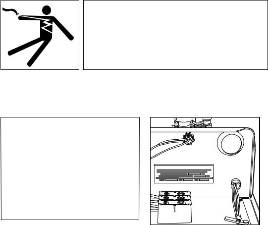
Electrical Connections
! ATTENTION ! |
WARNING:
Electrocution or serious injury may result when working on an energized circuit.
Disconnect power at the main breaker or service disconnect switch before working on the circuit.
Lock-out and tag the breaker to indicate that work is being performed on the circuit.
A qualified electrician must connect the main incoming power to the dishwasher in accordance with all local codes and regulations or in the absence of local codes in accordance with the National Electrical Code.
! ATTENTION !
Electrical and grounding connections
must comply with the National Electrical Code or in the absence of a National Code then all Local Electrical Codes.
A qualified electrician MUST compare the electrical power supply with the machine electrical specifications stamped on the MACHINE ELECTRICAL CONNECTION PLATE located inside the control cabinet before connecting the main power to the dishwasher.
MACHINE ELECTRICAL CONNECTION |
1.The incoming power to the dishwasher is made in the power terminal block, located inside the top-mounted control cabinet.
2.The electrician must connect the incoming power based on the information that is stamped on the Machine Electrical Connection Plate.
3.Any change to the Machine Electrical Connection Plate must be approved by the factory in advance.
4.A knock-out plug is provided at the rear of the control cabinet for electrical service connections.
5.Built-in electric booster heaters may have a separate main power connection.
6.Electric blower-dryers have a separate main power connection.
5
Installation
Electrical Connections (continued)
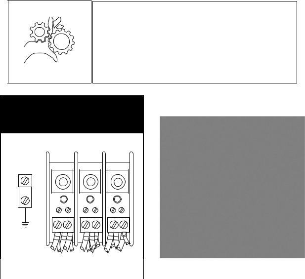
Motor Rotation
1.Check the converyor drive motor to ensure it rotates in the correct direction. The motor shaft must rotate in a counterclockwise direction when viewed from the rear.
2.The dishwasher motors are phased together; therefore, if the conveyor motor rotation is correct then the pumo motors will also be correct.
3.If the conveyor motor rotation is not correct, then reverse the L1 and L2 wires on the out put side of the dishwasher main ternimal block located inside the top-mounted control cabinet. Check to ensure the conveyor motor rotates counterclockwise after reversing the wires.
NOTE:
The prewash, wash and rinse pump motor shafts rotate clockwise when viewed from the rear. In addition, the motors have direction arrow labels indicating the properrotations.
WARNING:
Moving Conveyor Parts may cause INJURY OR DEATH. Keep hands and clothing clear of the conveyor when the
conveyor is moving.
USE EXTREME CAUTION WHEN THE CONVEYOR IS MOVING.
THREE PHASE
POWER CONNECTION
LINE IN
L1 L2 L3
GRD
Main Terminal Block Inside the Top-mounted Control |
Motor Direction Rotation Label on Motor Frame. |
Cabinet. |
|
|
|
6

Installation
(Optional) Table Limit Switch
A recommended option for any rack conveyor dishwasher is a table limit switch. The limit switch is installed at the end of the clean-end table and is designed to stop the conveyor and pumps in the event that dish racks back up on the clean-end table. This feature prevents possible damage to the conveyor due to jamming. The operation of the table limit switch is described below.
1.If the dishwasher is running and the table limit switch (TLS) is activated, the GREEN cycle light remains illuminated and the pumps and conveyor drive stop.
2.If the table limit switch (TLS) is deactivated within 5 minutes the dishwasher will resume the cycle where it left off; after 5 minutes the green light goes out and the START button must be pushed and a rack inserted into the machine.
3.Any dish racks left in the machine after 5 minutes have elapsed must be removed and processed again.
4.To restart the dishwasher, make sure the table limit switch (TLS) is clear, then push the GREEN START pushbutton and insert a rack into the load end of the machine. The green cycle light will illuminate; the pumps and conveyor motor will run.
Soiled-end table |
|
|
|
|
|
|
|
||
|
L-R Operation |
|||
|
|
|
|
|
Rack Conveyor Dishwasher
Table Limit Switch
Clean-end table |
7
Installation
Chemical Connections
1.Use a qualified detergent/chemical supplier for detergent/chemical and dispensing equipment needs.
2.Labeled detergent control circuit connection terminals are provided in the control cabinet for detergent and rinse agent/sanitizer dispensing equipment (supplied by others).
3.The illustration on the right, shows the terminal board for the machine.
4.The signal connection points include:
•Detergent signal 120VAC, 1A max load.
•Rinse aid/Sanitizer signal 120VAC, 1A load.
•Vent Fan 120VAC, 1Amp max amp load
5.A removable black plug is provided in the load end side of the wash tank for installation of the detergent conductivity cell.
Detergent
Probe Location
SIGNAL ONLY |
VENT FAN |
120V |
COMMON |
RINSE AID |
120V |
COMMON |
DETERGENT |
120V |
8

Installation
Vent Fan Signal Connection
1.A terminal block is provided inside the top-mounted control cabinet to provide a 120VAC, 1 AMP Max Load signal.
NOTE:
The Vent Fan Signal Connection supplies 120VAC to a control relay (supplied by others) when the dishwasher is ON and O VAC when the dishwasher is OFF. Power to operate the vent fan (supplied by others) must be supplied separately.
SIGNAL ONLY |
VENT FAN |
120V |
COMMON |
RINSE AID |
120V |
Machine Running & Table Limit Switch Signal Connections |
1.Connections are provided for systems that require a signal to indicate the dishwasher is running.
2.A signal connection is provided to indicate that the dishwasher has stopped due to a conveyor jam or when the clean dish table is full of racks and additional racks cannot exit the machine.
3.The table limit switch option is recommended to be installed on all dishwashers and can be ordered from the factory P/N 407400.
SIGNAL ONLY
MACHINE
RUNNING
TABLE
LIMIT
SWITCH
9
Installation
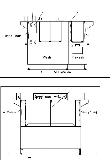
Curtain Locations
1.Refer to the illustrations below and hang the curtains as shown.
J-hooks are located in the corners of each section to accept the curtain rods.
• |
Standard long curtains |
24” x 20-1/4” |
• High hood long curtains |
24” x 22-3/4” |
|
• Standard medium curtains and DR |
24” x 13-1/4” |
|
• High hood short curtains |
24” x 20-1/4” |
|
• |
Final rinse curtain |
24” x 6-1/4” |
2.Make sure the that the short flaps of the curtains face the load end of the dishwasher. The long curtains always go on each end of the dishwasher.
Final Rinse Curtain
(DR) Dual Rinse Curtain
FR DR
Long Curtain
Long Curtain
NOTE:
Misplacing a curtain or failing to install a curtain will adversely affect the proper operation of the machine.
Dual Rinse Single Tank Dishwasher with Prewash Curtains.
|
Medium Curtain |
Power Rinse |
Wash |
R-L Direction |
|
Two Tank Dishwasher Curtain Locations
10
Installation
Hot Water Coil Tank Heat
Purging Air from the Dishwasher/Booster Heater System
CAUTION:
 PERMANENT DAMAGE to the hot water recirculating pump can


 occur if the air is not purged from the dishwasher/booster heater system prior to placing the dishwasher into service.
Follow the instructions on pages 9-10 to prevent damage to the dishwasher hot water recirculating pump.
The air trapped in the Dishwasher Hot Water Recirculating Pump and Water Lines must be purged. Refer to the illustration below and follow the procedure on the next page.
B
The dishwasher recirculating pump is located near the base at the booster end of the machine.
A
The air purge petcock is located behind the dishwasher lower front panel at the booster end of the machine.
11
Installation
Hot Water Coil Tank Heat
Purging Air from the Dishwasher/Booster Heater System (continued)
Refer to the illustration on the previous page and follow the procedure below to purge the air from the system. Plumbing and electrical service connections must be completed before purging the system.
To purge the air:
1.Make sure the dishwasher main power switch is OFF.
2.Make sure the main water supply valve located at the booster heater is OFF.
3.Open petcock (A) on the inlet side of the dishwasher hot water heater coil.
4.Remove the silver plug located in the center of the recirculating pump.
5.Turn the main water supply valve ON. Water will begin to fill the booster heater and the dishwasher heater coil.
6.Water and air will begin to flow out of the purge petcock and the recirculating pump and eventually only water will be observed.
7.Turn the booster heater power switch ON.
8.Turn the dishwasher power switch ON. The dishwasher wash tank will begin to fill with water.
9.Continue to observe the petcock and the recirculating pump and make sure that there is a steady stream of water is flowing from (A) and (B).
10.Replace the silver plug (B) in the center of the recirculating pump then close the petcock (A).
11.Turn the dishwasher power switch OFF.
12.Purging is complete.
12
Installation
Door Safety Switches
Dishwasher access doors are equipped with a door safety switch that automatically stops the dishwasher pumps and conveyor drive if a door is raised while the dishwasher is running. In addition, the dishwasher will not start if a door is left open.
1.If the dishwasher is running and a door is raised, the lighted GREEN START pushbutton goes out and the pumps and conveyor drive stop.
2.Check the interior of the dishwasher for any dish racks still in the machine. These dish racks must be washed again to ensure they are washed and sanitized completely.
3.To restart the dishwasher, make sure all doors are closed, then push the GREEN START pushbutton.
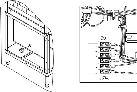
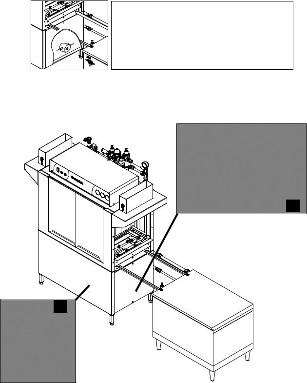
Spray Arm and Scrap Screen Installation
The illustrations below and on the following pages illustrate how to install and remove the spray arm assemblies and scrap screens.
Removing the lower spray arm assembly
13
Installation
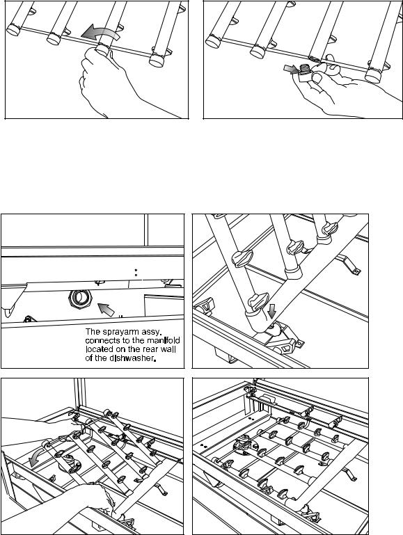
Removing the Spray Arm End Plugs
Installing the Lower Spray Arm Assembly
14

Installation
Installing the Upper Spray Arm Assembly
Removing the Spray Arm End Plugs
15

Installation
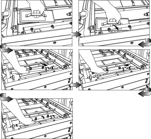
Removing the Dual Rinse (DR) scrap screens
Refer to the illustrations on this and the next page to remove and install the Dual Rinse (DR) scrap screens and rinse arm.
16 |
Installation
Installing the Dual Rinse (DR) scrap screens
17

Installation
Check list
1.Remove white protective film from the dishwasher exterior.
2.Install lower panels to the dishwasher.
3.Remove any foreign material from inside of the machine.
4.Check that the chemical supplies (supplied by others) are full.
5.Check to ensure the dishwasher drains are closed.
6.Install scrap screens, baskets and spray arms.
7.Turn main utilities to the dishwasher ON. (Power, water, steam if applicable).
8.Make sure doors are closed.
9.Turn dishwasher power switch ON. The tanks fill with water and the tank and booster heat will come on.
NOTE:
The dishwasher will not start if the tanks are not full of water. If the dishwasher fills for more than 20 minutes, the dishwasher will shut down and the green indicator light will flash. Check the drain valves and make sure they are fully closed, then push the power switch OFF and back ON and push the Green Start button to resume operation.
10.Check the digital tank water temperature gauges to ensure they indicate the proper levels. The final rinse gauge displays OFF when the final rinse is not running.
11.Check for leaks.
12.Push the START button.
13.Insert an empty dish rack into the load end of the dishwasher. The pumps and conveyor will run.
14.Carefully, open each dishwasher door to make sure the safety switch stops the conveyor and pumps.
15.Restart the dishwasher by pressing the START button.
16.Allow the dish rack to travel to the unload end of the dishwasher. The final rinse will run.
17.Allow the rack to exit the dishwasher. The dishwasher pumps and conveyor should stop when the rack exits the dishwasher.
18.Push the Stop button when the machine is running and the dishwasher should stop.
19.Push the START button, insert a dish rack into the load end of the machine and the pumps and conveyor should start.
20.Push the dishwasher Power Switch OFF. The dishwasher should shut down.
21.Drain the dishwasher and check that floor drains can handle the water volume leaving the dishwasher.
NOTE:
Opening a door will stop the pumps and drive. If the door is closed within 5 minutes the machine will resume operation where it left off. After 5 minutes the START switch must be pressed and a dish rack inserted into the machine for normal operation.
18
Operation
Operation
1.Check that the spray pipes, curtains, and scrap screens are in place and clean.
2.Check that the overflow drains are closed.
3.Check the chemical supplies (supplied by others). Turn on the detergent dispenser switches.
4.Turn on the exhaust vent system (if applicable), and make sure it is operating.
5.Close the door(s). Push the power switch ON..
Machine will begin to fill through the fill valve and the final rinse piping.
6.When the tanks are full, wait until the wash tank digital temerature guage has reached the proper temperature. The digital tank temperature gauges are located on the control cabinet. Minimum wash temperatures are:
• |
All single tank models - 160°F/71°C to 175°F/79°C |
• |
Single tank with Prewash - Wash Tank 160-175°F/71-79°C |
• |
The Prewash tank for all models has no temperature rating. |
• |
2-tank (Wash Tank) 150-165°F TO 66°F/74°C |
• |
(Power Rinse Tank) 165-180°F TO 74°F/82°C |
Final Rinse for all models is a minimum of 180-195°F/82-91°C. |
|
• |
Dual Rinse (if equipped) is 165-180°F/74-82°C rinse for all models. |
7. Push the Green START button. The Green Cycle Light illuminates indicating the dishwasher is ready for automatic operation.
8. Pre-scrape wares to remove large food particles and load wares into the dish racks.
9. Pegged racks are for plates and/or trays. Flat racks are for bowls and/or silverware. Spread silverware evenly in a single layer in a flat rack or upright (loosely packed) in a
cutlery rack/cylinder.
10. Push a dish rack into the load-end of the dishwasher until it contacts the idle pump switch lever, the conveyor and pumps will start.
11. The dishwasher will run for 90 seconds to wash, rinse and move the dish rack out of the unload end of the dishwasher.
12. Inserting another dish rack into the machine before the first rack exits will keep the dishwasher running until the last dish rack exits the machine.
13. Check the final rinse pressure and temperature as the racks pass through the final rinse. This final rinse pressure MUST be 20-22 psi and the final rinse temperature
MUST be a minimum of 180-195°F/82-91°C .
14.The pumps and the conveyor drive will automatically stop after the last rack exits the machine.
15.The machine may be stopped at any time during the cycle by pressing the red STOP pushbutton. The green light will go out.
16.Check the interior of the dishwasher for any dish racks still in the machine. These dish racks must be washed again to ensure they are washed and sanitized completely.
17.To restart, push the green START pushbutton and push another dish rack into the dishwasher load end until the pumps and conveyor start.
18.Repeat steps 7-10 until all wares are washed.
19
Operation
Door Safety Switches
Dishwasher access doors are equipped with a door safety switch that automatically stops the dishwasher pumps and conveyor drive if a door is opened while the dishwasher is running. In addition, the dishwasher will not start if a door is left open.
1.If the dishwasher is running and a door is opened, the GREEN cycle light remains illuminated and the pumps and conveyor drive stop.
2.If the door is closed within 5 minutes the dishwasher will resume the cycle where it left off; after 5 minutes the green cycle light goes out and the START button must be pushed and a rack inserted into the machine.
3.Any dish racks left in the machine after 5 minutes have elapsed must be removed and processed again.
4.To restart the dishwasher, make sure all doors are closed, then push the GREEN START pushbutton and insert a rack into the load end of the machine. The green cycle light will illuminate; the pumps and conveyor motor will run.
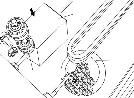
Pump Intake Screen and Dual Float Switch
Refer to the illustration below and note the location of the pump intake screen and dual float switch.
1.Make sure the pump intake screen is installed by sliding it on the bracket located in front of the wash pump intake.
2.Make sure the float balls on the dual float switch move freely on the float stem.
3.Check the interior of the tank for any foreign objects and make sure the drain screen is clean.
Pump Intake |
Screen |
Drain |
Screen |
Dual Float |
Switch |
Make sure tank is clean, the pump intake screen is installed and the dual float switch moves freely.
20
Blank Page
This Page
Intentionally
Left Blank
21
Operation
Scrap Screens
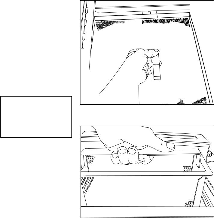
1.All models have scrap screens in the tanks.
2.Install two scrap screens in each wash tank making sure they fit securely without large gaps between them.
3.Install an internal refuse basket in each wash tank.
4.If equipped, install one large scrap screen and one external refuse basket in the prewash tank.
5.For machines equipped with a dual rinse section, install two scrap screens in the dual rinse section.
! ATTENTION !
NEVER REMOVE A SCRAP SCREEN OR REFUSE BASKET WHEN THE DISHWASHER IS RUNNING.
There are have scrap screens in the wash tank and one in the prewash tank
There is one refuse basket in the wash tank and an external basket in the prewash
22
 Loading...