

Page 1

Instructions for use
I
CONTENTS
1 - GENERAL 3
1.1 - GENERAL SAFETY REGULATIONS 3
1.1.1 - STANDARD SAFETY DEVICES 3
1.2 - FIELD OF APPLICATION 3
1.3 - OVERALL DIMENSIONS 3
1.4 - TECHNICAL DATA 4
2 - HANDLING AND LIFTING 4
3 - SETUP 5
3.1 - ANCHORING 5
3.2 - ELECTRICAL CONNECTION 5
3.3 - FITTING THE WHEEL FIXTURE SHAFT (SEE ATTACHED PROSPECTUS) 5
3.4 - FITTING THE WHEEL 5
4 - CONTROLS AND COMPONENTS 6
4.1 - AUTOMATIC DISTANCE AND DIAMETER GAUGE 6
4.2 - KEYBOARD AND DISPLAY 6
4.2.1 - FUNCTION MENU MANAGEMENT 7
5 - INSTRUCTIONS FOR USE OF THE WHEEL BALANCER 8
5.1 - USING THE GAUGE INSTALLED ON THE MACHINE 8
5.2 - AUTOMATIC DIMENSION SETTING 8
5.2.1 -
USING THE EXTENSION FOR THE DISTANCE GAUGE 9
5.3 - WHEEL BALANCING 9
5.3.1 - MEASURING UNBALANCE 9
5.3.2 - CORRECTING THE UNBALANCE 10
5.4 - RECALCULATING UNBALANCE VALUES 10
5.5 - UNBALANCE OPTIMISATION 11
5.6 - AUTOMATIC MINIMISATION OF STATIC UNBALANCE 12
6 - SET UP 13
6.1 - AUTODIAGNOSTICS 13
6.2 - AUTOCALIBRATION 13
6.3 - MANUAL DIMENSION PRESETTING (use only in particular cases or for test) 14
6.3.1 - USING THE EXTENSION FOR THE DISTANCE GAUGE 14
6.6 - AUTOMATIC GAUGES 15
6.6.1 - RIM DISTANCE GAUGE 15
6.6.2 - DIAMETER GAUGE 16
7 - ERRORS 17
8 - ROUTINE MAINTENANCE 18
8.1 - REPLACING THE PROTECTION FUSES 18
I 0627 - 1
GB
Page 2

I 0627 - 2
I 0310 - 2
GB
Page 3
1 - GENERAL
▪
▪
▪
▪
▪
▪
▪
▪
▪
▪
▪
1.1 - General safety regulations
The wheel balancer may only be used by duly authorized and trained personnel.
The wheel balancer must not be used for purposes other than those described in the instruction manual.
The wheel balancer may not be modifi ed in any way, except for modifi cations made explicitly by the
manufacturer.
Do not remove the safety devices. Any work on the machine must be carried out by specialised personnel
only.
Avoid using strong jets of compressed air for cleaning.
Use alcohol to clean plastic panels or shelves (AVOID LIQUIDS CONTAINING SOLVENTS).
Before starting the balancing cycle, make sure that the wheel is securely locked on the fl ange.
The machine operator must not wear clothes with fl apping parts. Do not allow unauthorized personnel to
approach the wheel balancer when the cycle is running.
Avoid placing objects in the bases which could compromiseproper functioning of the wheel balancer.
1.1.1 - Standard safety devices
Two-handed control to start the balancing spin. During the spin, the operator is obliged to stay in a lateral
position, away from the wheel.
Slow rotation speed.
1.2 - Field of application
The wheel balancer has been designed for balancing motorcycle wheels (max. wheel weight = 30 kg).
It can be operated in a temperature range of 0° to + 45° C.
The following functions are provided: Unbalance optimisation; Autodiagnostics; Autocalibration.
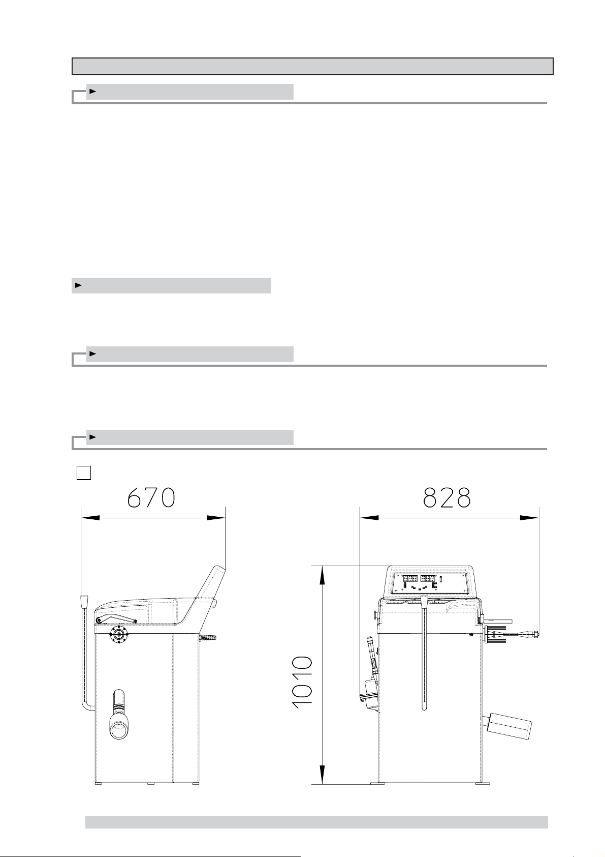
1.3 - Overall dimensions
1
I 0627 - 3
GB
Page 4
1.4 - Technical data
Weight (excluding adapter) ~ 70 kg
Single-phase power supply
Protection class IP 54
Max. power absorbed 800 W
Balancing speed
Cycle time for average wheel (14 kg) 6-8 seconds
Max. resolution of measurement 1 gram
Position resolution ± 1.4 °
Average noise < 70dB (A)
Rim-machine distance 0 - 325
Rim width setting range 1.5” - 20” or 40 - 510 mm
Diameter setting range 10” - 30” or 265 - 765 mm
115/230 V - 50/60 Hz AC
12-24 V DC (
< 80 min
use without motor)
-1
mm (with extension + 10)
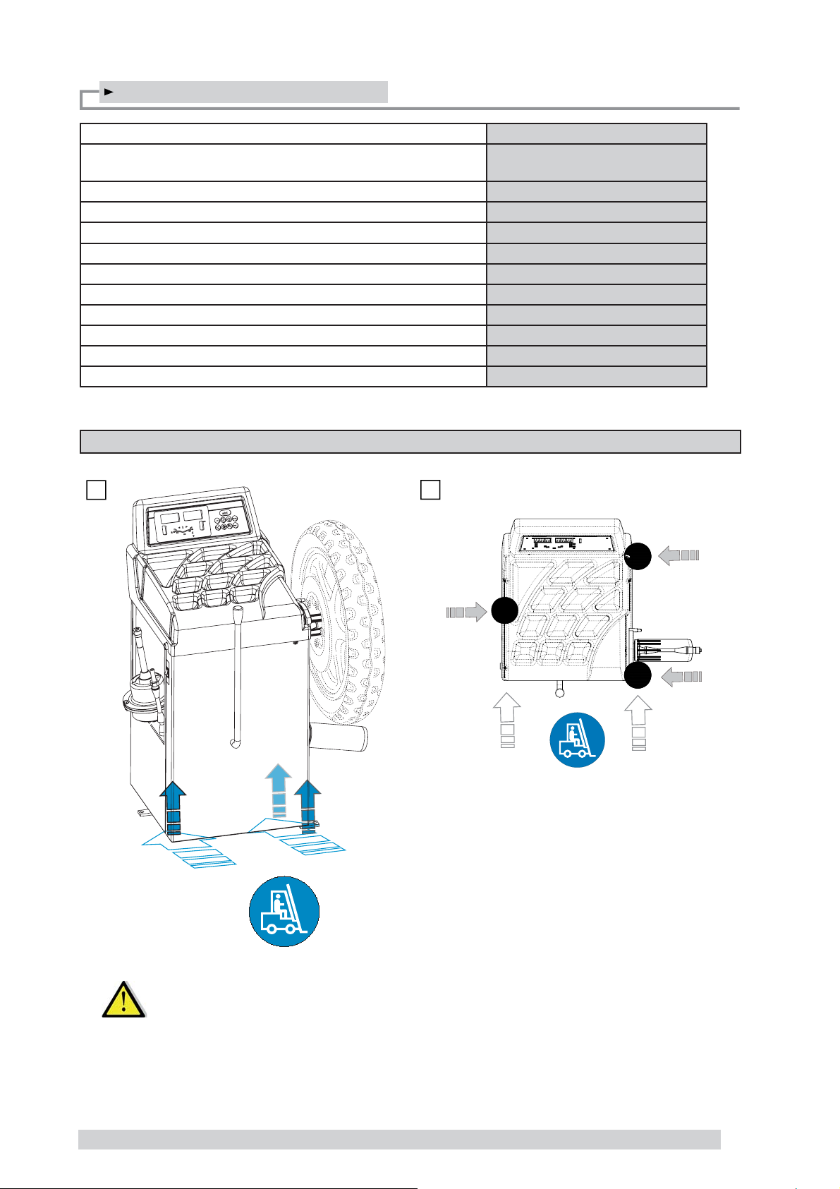
2 - HANDLING AND LIFTING
2
2a
I 0627 - 4
I 0310 - 4
GB
NB: DO NOT LIFT THE WHEEL BALANCER USING OTHER GRIPS.
Page 5
3 - SETUP
▪
▪
▪
▪
3.1 - Anchoring
The machine can operate on any fl at non resilient fl oor. Make sure that the machine rests solely on the three support
points provided (
3.2 - Electrical connection
(A) The machine is supplied with a single- phase mains cable plus earth (ground).
The power supply voltage (and mains frequency) is indicated on the machine identifi cation plate and cannot be
changed. Connection to the mains must always be made by expert personnel. The machine must not be set up
without proper earthing. Connection to the mains must be made with a slow-acting safety switch calibrated to 3A
(230V) or 8A (115V) . See enclosed diagram.
3.3 - Fitting the wheel fi xture shaft (see attached prospectus)
The balancing machine's main advantage is its fi xed shaft tool. This means that when the wheel is fi tted on the tool, it
is free to turn on its own bearings, exactly reproducing the conditions of use when it is fi tted on the motor bike.
Balancing is not affected by inaccuracies in the wheel-fl ange-shaft coupling typical of traditional rotating shaft balan
cing machines. This means that you can achieve the best possible accuracy.
Use the AF12 or AF15 tools with cones and axial blockage rings for wheels with traditional fi xture
(through- journal).
Use the rotating AGF tool for wheels with outboard fl anged fi xture (BMW, Honda).(See specfi c brochure for correct
assembly).
Push the chosen tool well home into the balancing machine’s hollow shaft and block it in position by tightening the
screws accessible from the baseplate hole.
Fig. 2a).
NOTE ON AGF TOOL: Remove it from the balancer after use to avoid permanent deformation of
brush bristles.
3.4 - Fitting the wheel
The AF12 and AF15 fi xed shaft tools enable you to fi t wheels with a maximum hole of 35 mm on their own bearings.
Do not overtighten the threaded ring, as this would put excessive axial load on the bearings. When you fi t the wheel,
you will notice that the brush adapts automatically (radially) to the shape of the wheel hub. During balancing operations, the brush will turn together with the wheel and transmit the motion to the balancing machine’s built-in position
transducer. If you use the special AGF tool, the rotating movement will be transmitted to the brush by the rotating part
of the tool.
I 0627 - 5
GB
Page 6
4 - CONTROLS AND COMPONENTS
4.1 - Automatic distance and diameter gauge
Allows automatic measurement of the distance from the machine and the wheel diameter at the counterweight
application point. The same gauge can be used to position the counterweights correctly inside the wheel, using the
specifi c function that suggests the position memorised during measurement inside the rim.
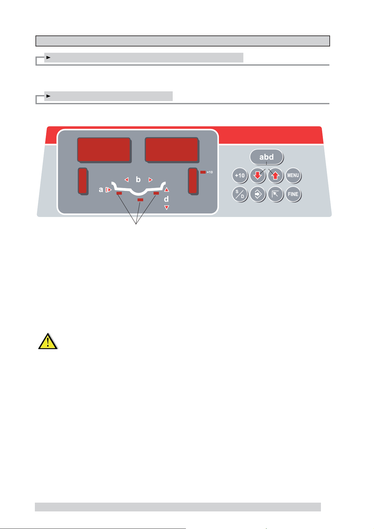
4.2 - Keyboard and display
1
3
12
1-2 UNBALANCE VALUE digital indicators
Inside/outside
3-4 UNBALANCE POSITION indicators
Inside/outside
5 Distance extension enable button
6 Buttons for manual setting of DISTANCE /
DIAMETER / WIDTH
7 FUNCTION MENU button
2
5
6
4
9
8
8 Correction mode selection button
9 MENU selection confi rmation button
10 HOME button
11 Unbalance reading button < 5 g (0.25 oz)
12 Selected correction mode indicators
10
7
11
N.B.: Press the buttons with your fi ngers only.
Do not use the counterweight grippers or other pointed objects.
I 0627 - 6
I 0310 - 6
GB
Page 7

4.2.1 - Function menu management
See chapter on unbalance optimisation
diameter
mm/inch
mm/inch
width
approx. -5 g or
0.1-0.25 oz
See chapter on AUTODIAGNOSTICS
See chapter on AUTOCALIBRA TION
g/oz unit of
measure
unbalance
*
*
Calibration of automatic RIM DISTANCE gauge (see SETUP)
Calibration of automatic DIAMETER gauge (see SETUP)
CONFIRM
CONFIRM
CONFIRM
CONFIRM
RETURN TO MEASUREMENT FRAME
* N.B.: If such indications fail to appear, contact Technical Service.
I 0627 - 7
GB
Page 8

5 - INSTRUCTIONS FOR USE OF THE WHEEL BALANCER
5.1 - Using the gauge installed on the machine
3
Use the gauge always in the upper position A
3a
Indication of gauge in movement
5.2 - Automatic dimension setting
3b
Setting valid for the DYNAMIC and STATIC correction modes.
3c
Extract the gauge up to the barycentre of the inside correction
weight.
Hold it in this position until the symbol shown in Fig. 3d is
displayed.
3d
Indication of dimensions acquired
Return the gauge to rest position. The machine has automatically
detected DISTANCE + DIAMETER and goes to MANUAL WIDTH
SETTING.
I 0627 - 8
I 0310 - 8
GB
Set accurately the distance ‘b’ between the barycentres of the
weights where they will be applied (
PRESETTING)
3e
MANUAL DIMENSION
Page 9

Using the extension for the distance gauge
5.2.1 -
4
The extension increases the distance measuring range of the gauge by 10 cm (
Proceed as indicated below:
- Fit the extension into place on the distance gauge.
- Press the button
(the LED comes on)
Extension
Fig. 4)
- Proceed with the distance measurement as already described.
- The led goes off
- Proceed with manually setting the width.
5.3 - Wheel balancing
5.3.1 - Measuring unbalance
▪ Move the front lever to the right bringing the pulley into contact with the tyre and press the run button on the side
holding the lever pushed in order to spin the wheel. If used without motor, spin the wheel by hand respecting the
correct direction of rotation (anticlockwise).
▪ Release the lever and the START key when the displays go off, the machine will then start making measurements.
▪ When the displays show the measurement values, brake the wheel by re-establishing contact with the pulley, which
is braked when the motor is off. Instruments 1 and 2 will keep the dynamic unbalance values in their memories.
When balancing for static, the value is shown on display 1.
▪ LEDs on displays 3 and 4 will indicate the correction position. If all the LEDs are alight, this means that the correc
tion weight should be applied to the vertical apex. They mean the same when balancing for static.
▪ For small diameter wheels (scooters), launch always the wheel by hand in anticlockwise direction (see arrow).
Measurement always begins when the displays go off.
I 0627 - 9
GB
Page 10

5.3.2 - Correcting the unbalance
STATIC: Apply two identical correction weights at the highest point of the wheel, one on the inside shoulder and
the other on the outside shoulder of the rim. Each weight is half the value indicated by the display.
If you make the correction with lead wire, springs or clamps applied to the spokes, divide it onto one, tow
or more spokes, according to the size of the unbalance.
DYNAMIC: Apply the adhesive weights to the shoulders of the wheel rim in the positions indicated by the display for
each of the sides.
5
Correction of inner side Correction of outer side
Digital readouts with LED ‘s 3 - 4 lit up indicate the correct angular wheel position to mount the counterweights (12
o’clock position).
In the event of unbalance less than the selected threshold value
0 is displayed in place of the unbalance
value , with
N.B.: In rare cases and in temperature conditions near 0°, the wheel balancer automatically activates a
special measuring cycle involving two successive measurements.
During the unbalance measurement, the word “START” reappears to indicate to the user to bring
the wheel back up to speed. The accuracy of the unbalance values and the reliability of the wheel
balancer remain unchanged.
it is possible to read the values below the selected threshold gr. by gr.
5.4 - Recalculating unbalance values
▪ Set the new dimensions as described above.
▪ Press , without repeating the spin.
▪ The new recalculated unbalance values will be displayed.
I 0627 - 10
I 0310 - 10
GB
Page 11

5.5 - Unbalance optimisation
- This function serves to reduce the amount of weight to be added in order to balance the wheel
- It is suitable for static unbalance greater than 30 g.
- It improves the residual eccentricity of the tyre.
No previous unbalance
measurement
Unbalance already measured
Spin the wheel
TYRE POSITION
RIM POSITION
Stop the wheel
▪ Mark with chalk a reference point on the adapter and rim.
▪ With the aid of a tyre remover, turn the tyre on the rim by 180°.
▪ Refi t the wheel with the reference mark coinciding between rim and
adapter.
▪ Spin the wheel
▪ Stop the wheel
▪ RH display: percentage reduction
▪ LH display: actual static unbalance which can be reduced by rotation.
▪ Mark the two positions of the rim and tyre, and turn the tyre on the rim until
the positions correspond in order to obtain the optimization on the display.
CANCEL OPTIMISATION IN ANY PHASE.
I 0627 - 11
GB
Page 12

5.6 - Automatic minimisation of static unbalance
Initial unbalance
Phase shift
Possible approximations
static residue
With traditional wheel
balancer
static residue
static residue
Choice with minimum
static unbalance
static residue
This program is designed to improve the quality of balancing without any mental effort or waste of time by the operator. In fact, using the normal weights available on the market (pitch of 5 in every 5 g) and applying the two counterweights which a conventional wheel balancer rounds to the nearest value, a residual static unbalance of up to 4 g
may result. The damage of such approximation is emphasized by the fact that static unbalance is the cause of most
disturbances on motorcycle. This new function automatically indicates the optimum entity of the weights to apply by
approximating them in an “intelligent” way according to their position in order to minimize residual static unbalance.
I 0627 - 12
I 0310 - 12
GB
Page 13

6 - SET UP
6.1 - Autodiagnostics
performs tests useful for maintenance staff.
6.2 - Autocalibration
For autocalibration proceed as follows:
▪ Fit a wheel of average dimensions even one that is unbalanced.
▪ Set the exact dimensions of the wheel mounted.
CAUTION !! Setting incorrect dimensions will result in the machine not being properly calibrated
and hence all the subsequent measurements will be incorrect until a new autocali
bration is performed with the correct dimensions!!
- Perform a spin under normal conditions
- Stop the wheel
- Add a 30 g. sample weight (1.00 oz) on the outside in any angular position.
- Perform a spin
- Stop the wheel
- Shift the sample weight from the outside to the inside keeping the same angular
position.
- Perform a spin
- Stop the wheel
- Turn the wheel until the sample weight is in the 12 o’clock position.
END OF AUTOCALIBRATION
CANCEL AUTOCALIBRATION IN ANY PHASE.
I 0627 - 13
GB
Page 14

6.3 - Manual dimension presetting (Use only in particular cases or for test)
6
-
Reading point
- Set the distance “a” of the barycentre of the inside correction
weight
- It is essential that you determine and set accurately the distance
‘b’ between the barycentres of the weights where they will be
applied.
- Set the nominal diameter ‘d’ as shown on the tyre.
6.3.1 - Using the extension for the distance gauge
7
Reading point
Extension
▪ Fit the extension on the distance gauge
▪ Proceed with measuring the distance as described in Fig. 7
▪ Having read value “a” on the dial, reset the gauge to “0” and manually set the value “a + 100 mm“
▪ Manually set the diameter and the width, as already described.
I 0627 - 14
I 0310 - 14
GB
Page 15

6.6 - Automatic gauges
6.6.1 - Rim distance gauge
- Shift the distance gauge to position
- Move the gauge to position 150 , press
CORRECT CALIBRATION
- Return the gauge to rest position
- The wheel balancer is ready for operation
N.B.: In the event of errors or faulty operation, the writing
the gauge to position
the error persists, contact the Technical Service Department. In the event of incorrect input in
the rim distance gauge calibration function, press
0 and repeat the calibration operation exactly as described above. If
0 , keeping it quite still, press
P. 0 appears on the display : shift
to cancel it.
I 0627 - 15
GB
Page 16

6.6.2 - Diameter gauge
Place the gauge on the brush as shown in the fi gure and press
- The number 341 ± 1° appears on the left display .
- Position the distance gauge 20 mm from the edge of the brush as
shown in the fi gure
- The number 272 ± 3° should appear on the left display.
- If not, press the button
the number 272 appears on the left display.
- Return the gauge to rest position.
In the event of incorrectly accessing the diameter gauge
holding the gauge still at 20 mm:
I 0627 - 16
I 0310 - 16
GB
calibration function, press to cancel it.
Page 17

7 - ERRORS
During machine operation there may be various causes of malfunctioning which, if detected by the microprocessor,
are indicated on the display:
ERRORS CAUSE CHECKS
Black The wheel balancer does not come on. 1. Check proper connection to the mains.
Err. 1 No rotation signal. 1. Check belt tautness.
Err. 2 Too low speed during measurement.
Err. 3 Too high unbalance. 1. Check the wheel dimension setting.
Err. 4 Rotation in opposite direction.
Err. 7 /
Err. 8 /
Err. 9
During the unbalance measurement
revolutions, the wheel speed has fallen
to below 42 rpm.
After pressing [START], the wheel
starts turning in the opposite direction
(anticlockwise).
NOVRAM parameter read error 1. Repeat machine calibration
2. Check and if necessary replace the fuses on the power board.
3. Replace the computer board.
2. Check functioning of the phase generator and, in particular, the reset
signal.
3. Replace the phase generator.
4. Replace the computer board.
1. Check that a vehicle wheel has been mounted on the wheel balancer.
2. Verify belt tautness.
3. Verify the function of the phase pick-up board and, in particular, the reset
signal.
4. Replace the computer board.
2. Check the sensor connections.
3. Run the machine calibration function.
4. Mount a wheel with a more or less known unbalance (less than 100
grams) and check the machine response.
5. Replace the computer board.
1. Check the connection of the UP/DOWN - RESET signals of the phase
generator.
2. Shut down the machine.
3. Wait for at least ~ 1 min.
4. Restart the machine and check proper functioning.
5. Replace the computer board.
Err. 11 Too high speed error.
Err.14/
Err.15/
Err.16/
Err.17/
Err.18
Err. 22 Maximum number of spins possible for
Err. 23 The wheel does not slow down. 1. Remember to release the START/STOP selector when the displays go
Err. 32/
Err. 33/
Err. 34/
Err. 35/
Err. 36/
Err. 37
The average spinning speed is greater
than 240 rpm.
Unbalance measurement error. 1. Check functioning of the phase generator.
the unbalance measurement has been
exceeded.
Errors related to test functions of the
wheel balancer.
1. Check if there is any damage or dirt on the timing disc.
2. Verify the function of the phase pick-up board and, in particular, the reset
signal.
3. Replace the computer board.
2. Check the sensor connections.
3. Check the machine earthing connection.
4. Mount a wheel with more or less known unbalance (less than 100
grammes) and verify the response of the machine.
5. Replace the computer board.
1. Check that a vehicle wheel has been mounted on the wheel balancer.
2. Verify belt tautness.
3. Verify the function of the phase pick-up board and, in particular, the reset
signal.
4. Replace the computer board.
off.
2. Check functioning of the phase generator.
3. Replace the computer board.
1. Cancel the error and continue using the wheel balancer as normal.
I 0627 - 17
GB
Page 18

8 - ROUTINE MAINTENANCE
Before carrying out any operation on the machine, cut the power supply to the machine.
8.1 - Replacing the protection fuses
A protection fuse is fi tted on the power board, accessible by dismantling the weight shelf (see Exploded Drawings). If
fuses require replacement, use ones with an identical current rating.
If the fault persists, contact Technical Service.
NONE OF THE OTHER MACHINE PARTS REQUIRE MAINTENANCE.
I 0627 - 18
I 0310 - 18
GB
 Loading...