


(with price)
POCKET TELEVISION
TV-600B
DECEMBER 1994 |
|
|
Page |
Specifications............................................................................................. |
1 |
Block Diagram ........................................................................................... |
2 |
Circuit Description...................................................................................... |
3 |
Adjustment |
|
Linear PCB.......................................................................................... |
5 |
A/D PCB .............................................................................................. |
9 |
Troubleshooting ....................................................................................... |
10 |
Printed Circuit Boards .............................................................................. |
11 |
Wiring Diagram ........................................................................................ |
15 |
Exploded View / Disassembly.................................................................. |
16 |
Electrical Parts List .................................................................................. |
17 |
Mechanical Parts List............................................................................... |
23 |
IC and Transistor Lead Identification ....................................................... |
24 |
Schematic Diagrams and Waveforms ..................................................... |
26 |
INDEX
R
|
SPECIFICATIONS |
|
||
|
|
|
|
|
|
Item |
|
Specification |
|
|
|
|
||
1. |
Reception channels |
VHF : 2 ~ 13 ch UHF : 14 ~ 69 ch |
||
|
|
|
|
|
2. |
Power voltage |
DC 6.0 V |
|
|
|
|
|
|
|
3. |
Power consumption |
Approx. 3.4 W |
|
|
|
|
|
|
|
4. |
Current consumption |
Approx. 566 mA |
|
|
|
|
|
|
|
5. |
Battery life (with alkaline batteries) |
Approx 3.0 hours |
|
|
|
|
|
|
|
|
|
Batteries |
: 4 AA size batteries |
|
6. |
Power supply |
Car adaptor : CA-K65 |
|
|
|
|
AC adaptor |
: ADK-65, 64 |
|
|
|
|
|
|
|
|
Earphone jack |
: 3.5ø mini |
|
7. |
Connection terminals |
External power jack |
: 6.0V DC IN |
|
|
|
External antenna jack |
: 3.5ø mini |
|
|
|
Audio / Video jack |
: 3.5ø |
|
|
|
|
|
|
8. |
Screen size |
2.2 inches |
|
|
|
|
|
|
|
9. |
No. of Picture element |
39,600 (110 × 360) dots |
|
|
|
|
|
||
10. |
Dimensions |
81 (W) × 32 (D) × 131 (H) mm |
||
|
|
3 1/5" (W) × 1 1/4" (D) × 5 1/6" (H) |
||
|
|
|
||
11. |
Weight |
220 g excepting batteries |
||
|
|
7.8 oz excepting batteries |
||
|
|
|
|
|
12. |
Standard accessories |
Test batteries (R6 × 4) |
|
|
|
|
|
|
|
|
|
AC adaptor |
|
: AD-K65, 64 |
13. |
Options |
Car adaptor |
|
: CA-K65 |
|
|
RF connector |
: CF-13 |
|
|
|
Antenna matching device : AS-35S |
||
|
|
|
|
|
14. |
Body color |
Black |
|
|
|
|
|
|
|
— 1 —
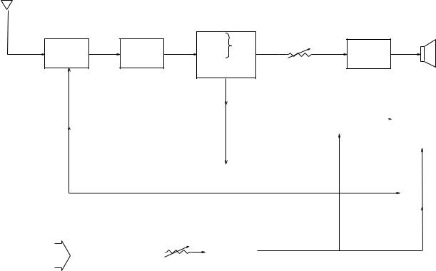
BLOCK DIAGRAM
Antenna
3IC200
1 TU200 |
2 Q200 |
Video |
4 IC600 |
Speaker |
|
|
VR600 |
|
|
|
|
Sound DetDet. |
|
|
|
|
Audio |
|
|
Tuner |
IF Amp. |
FM |
Amp. |
|
|
|
AFT Circuit |
Volume |
|
|
|
AGC Circuit |
Control |
|
7 |
IC500 |
5 |
IC300 |
|
|
|
||
|
|
|
||||||
|
|
|
|
|
|
|||
Tuning |
|
|
|
|
|
|
|
|
Voltage |
|
|
Chroma |
|
Common |
|
LCD |
|
Generator |
|
|
Circuit |
|
Driver |
|
||
|
|
|
|
|
||||
|
|
|
|
|
|
|
|
|
|
|
|
|
|
|
|
|
|
6IC700
|
|
|
|
Osc. |
|
|
|
|
|
|
|
|
Display |
|
|
|
|
|
|
|
|
Segment |
||||
|
|
|
|
|
Control |
|
|
|
|
|
|
|
A-D Converter |
|
|
Driver |
|
|
|
|
|
Auto-Tuning |
|
|
|
|
|
|
|
|
|
||||
|
|
|
|
|
Control |
|
|
|
|
|
|
|
|
|
|
|
|
|
|
VR800 |
|
8 Q800~Q802, Q804~Q806 |
|
|||
|
VCC2 (3.95±0.02 V) |
|
|
|
|
|
||
Power |
|
|
|
Display |
|
|
||
VCC6 (30.5~39.0 V) |
|
|
|
Voltage |
|
|
||
|
|
|
|
|
||||
Supply |
|
|
|
|
|
|||
VCC7 (53.5~72.5 V) |
Brightness |
|
Generator |
|
|
|||
|
VEE1 (–6.3~–7.9 V) |
|
|
|
|
|
||
|
Control |
|
|
|
|
|
||
|
|
|
|
|
|
|
||
1— Color Tuner: TU200 TEPU5-02
Selects a desired radio wave and changes it to the video IF signal.
2— Video IF Amp.: Q200 2SC4238
Amplifies the video IF signal output from the tuner TU by 10 times (20 dB).
3— Video Det./Sound Det./FM Det./AFT/AGC: IC200 M51348FP
Eliminates the carrier wave in the video IF signal, and picks up the video signal and the sound IF signal. Also, the sound signal is picked up from the sound IF signal by FM detection.
4— Audio Amp.: IC600 NJM2070M Sound amplification.
5— Chroma Circuit: IC300 M52042FP
Generates the tricolor (red, green, and blue) from the video signal.
6— Osc./A-D Converter/Display Control/ Auto-Tuning Control : IC700 MSM6625-02 GSK-640F
Converts the color signal into a digital signal.
Also, generates the clock pulse for the display and controls the display.
7— Tuning Voltage Generator: IC500 MSC1169MS-K
Generates the tuning voltage with the tuning pulse (TU) output from 6.
8— Display Voltage Generator: Q800~Q802, Q804~Q806, 2SD601A-R x 4, 2SB709A-R, 2SD1149-S Generates the display voltages V0 ~ V4 with VEE1 and VCC7 outputs from the power supply.
—2 —
CIRCUIT DESCRIPTION
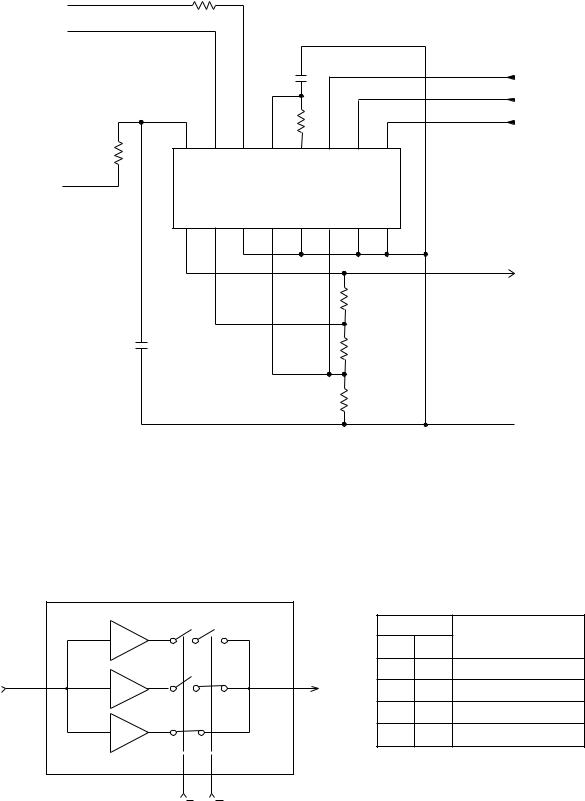
TUNING VOLTAGE GENERATOR
BT
BS
Vcc 16
VCC6  VREF
VREF
1
|
|
|
|
|
|
TU |
|
|
|
|
|
|
H/L |
15 |
14 |
13 |
12 |
11 |
10 |
BU |
9 |
||||||
BS |
BT |
IN |
OUT |
TU |
H/L |
U/V |
|
IC500 MSC1169MS-K |
GND |
||||
U1 |
U2 |
VL1 |
VL2 |
VH1 |
VH2 |
|
2 |
3 |
4 |
5 |
6 |
7 |
8 |
|
|
|
|
|
|
VREF |
|
|
|
|
|
R500 |
|
|
|
|
|
|
R501 |
|
|
|
|
|
|
R502 |
|
 GND
GND
Figure 1
This circuit generates the DC tuning voltage BT for selecting a channel with a TU pulse being output from IC700.
IC500 has 3 circuits for converting pulses to voltages; it selects one of VHF-L, VHF-H, or UHF, and causes the tuning voltage to be output from the OUT terminal (pin 12). Figure 2 and Table 1 show the conditions for selection.
|
|
IC500 |
|
|
|
|
|
VHF |
Inputs |
Function |
|
|
|
U/V |
H/L |
||
|
|
-L |
|
||
|
11 |
|
L |
L |
VHF-L receiving |
TU |
VHF |
12 |
|
|
|
|
L |
H |
VHF-H receiving |
||
|
-H |
||||
|
|
OUT(BT) |
|
|
|
|
|
|
L |
UHF receiving |
|
|
|
|
H |
||
|
|
UHF |
H |
H |
UHF receiving |
|
|
9 |
10 |
|
Table 1 |
|
|
U/V |
H/L |
|
|
|
|
Figure 2 |
|
|
|
— 3 —

POWER SUPPLY
VCC1-1 |
|
T100 |
|
CP100 |
2 |
|
|
|
|
|
R111 |
Vref |
|
|
|
Q111 |
|
1 |
|
|
|
|
|
||
|
C135 |
|
|
|
|
|
|
|
|
|
|
|
|
|
|
|
|
|
R115 |
9 |
|
|
|
|
|
|
|
|
D100 |
|
R102 |
C140 |
|
|
|
|
|
|
|
|
|
|
|
VR100 |
|
|
C145 |
|
|
|
Q100 |
|
|
|
|
|
|
|
|
|
|
C100 |
C105 |
R101 |
Q101 |
R117 |
CP104
VCC2-2 |
VCC2-3 |
|
L102 |
R133 |
|
D155 |
|
|
3 |
VCC7 |
|
D152 |
||
CP108 |
||
|
4
VCC6
CP107
5
VCC2
|
|
L101 |
CP109 |
|
|
|
|
|
|
6 |
D152 |
|
|
|
|
D150 |
|
|
|
7 |
|
|
|
VEE1 |
|
|
|
|
|
|
|
|
|
CP110 |
|
|
|
|
C115 |
|
C112 |
C110 |
C113 |
C114 |
GND
Figure 3
The power supply consists of a DC-DC converter and causes the voltages to be output as shown in Table 2.
Name |
Voltage |
Function |
|
|
|
VCC2 |
3.95 ± 0.02 V |
Main voltage |
|
|
|
VCC6 |
30.5 ~ 39.0 V |
Tuning voltage |
|
|
|
VCC7 |
53.5 ~ 72.5 V |
Tuning voltage/Display voltage |
|
|
|
VEE1 |
–6.3 ~ –7.9 V |
Display voltage |
|
|
|
Table 2
— 4 —
|
|
ADJUSTMENT |
LINEAR PCB |
|
|
Items To Be Adjusted |
|
|
|
|
|
|
Item |
Measuring Instrument |
|
|
|
|
VCC2 voltage setting |
Voltmeter |
|
|
|
|
Video detection coil adjustment |
TV signal generator, pattern generator, oscilloscope, |
|
|
low-pass filter |
|
|
|
|
AFT coil adjustment |
Sweep generator, oscilloscope, voltmeter |
|
|
|
|
Contrast adjustment |
TV signal generator, pattern generator, oscilloscope |
|
|
|
|
AGC adjustment |
TV signal generator, pattern generator, IF levelmeter |
|
|
|
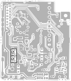
Adjustment And Test Point Locations
 T201
T201
 T200
T200
Top View
— 5 —
VR100
|
TP7 |
|
TP5 |
TP2 |
TP1 |
|
||
|
PadIF |
|
VR300 |
VR200 |
|
|
|
|
TP4


 TP3
TP3
Bottom View
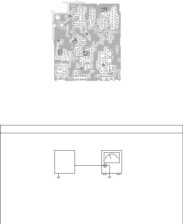
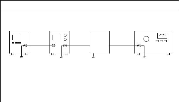
Equipment Connection / Adjustment Procedure
|
VCC2 Voltage Setting |
TV-600 |
Voltmeter |
Set |
|
|
Output |
|
TP1 |
|
|
|
|
|
|
|
|
|
|
|
|
|
|
|
|
|
|
|
|
|
|
|
|
|
|
|
|
|
|
|
|
|
|
|
|
|
|
|
|
|
|
|
|
|
|
|
|
|
Input |
Input |
|
Input |
Adjust |
Output |
Output |
Result |
|||||||
Connection |
Point |
|
Signal |
Connection |
Point |
||||||||||
|
|
|
|||||||||||||
|
|
|
|
|
|
|
|
|
|
|
|
|
|
|
|
|
|
|
|
|
|
|
|
|
|
|
VR100 |
Voltmeter |
TP1 |
Adjust for 3.95 ± 0.02 V |
|
|
|
|
|
|
|
|
|
|
|
|
reading on voltmeter. |
||||
|
|
|
|
|
|
|
|
|
|
|
|
|
|
|
|
|
|
|
|
|
|
|
|
|
|
|
|
|
|
|
|
— 6 —

Video Detection Coil Adjustment
* Desolder the IF pad to open. |
|
|
|
|
|||
Pattern |
|
Signal |
|
TV-600 |
|
|
|
generator |
|
generator |
|
Set |
|
Oscilloscope |
|
|
|
|
|
|
Low-pass |
|
|
|
|
|
Input |
|
filter |
|
|
|
|
|
Output |
|
|||
|
|
|
TP2 |
|
TP3 |
|
|
Input |
Input |
Input |
Adjust |
Output |
Output |
Result |
|
Connection |
Point |
Signal |
Connection |
Point |
|||
|
|
||||||
Pattern |
|
Color bar |
|
|
|
|
|
generator |
|
|
Low-pass filter |
TP3 Adjust for DC level at mini- |
|||
|
TP2 |
45.75 MHz |
T200 |
||||
Signal |
Oscilloscope |
||||||
|
40 ± 3 dBμ |
|
|
|
|||
generator |
|
|
|
|
|
||
|
|
|
|
|
|
||
AFT Coil Adjustment
* Desolder the IF pad to open.
Sweep |
TV-600 |
Oscilloscope |
Voltmeter |
generator |
Set |
||
Input |
|
Output |
|
TP2 |
|
TP4 |
|
|
|
|
|
|
|
|
|
|
|
|
|
|
|
|
|
|
|
|
|
|
|
|
|
|
|
|
|
|
|
|
|
|
|
|
|
|
|
|
|
|
|
|
|
|
|
|
|
|
45.75±5 MHz |
|
|
|
|
|
Adjust for 2.0 ± 0.2 V reading |
||||
Sweep |
|
|
|
|
|
|
|
|
on voltmeter. |
|||||
|
TP2 |
(Sweep) Marker: |
T201 |
Voltmeter |
TP4 |
|||||||||
|
Confirm that the marker is at |
|||||||||||||
generator |
|
45.75 MHz |
Oscilloscope |
|||||||||||
|
|
|
|
|
the middle of S-curve on oscil- |
|||||||||
|
|
|
|
70 ± 3 dBμ |
|
|
|
|
|
|||||
|
|
|
|
|
|
|
|
|
loscope. |
|||||
|
|
|
|
|
|
|
|
|
|
|
|
|
|
|
Contrast Adjustment
* Desolder the IF pad to open.
Pattern |
Signal |
TV-600 |
|
generator |
generator |
Set |
Oscilloscope |
|
Input |
|
Output |
|
TP2 |
|
TP5 |
|
|
|
|
|
|
|
|
|
|
|
|
|
|
|
|
|
|
|
|
|
|
|
|
|
|
|
|
|
|
|
|
|
|
|
|
|
|
|
|
|
|
|
|
|
|
|
|
|
|
|
Pattern |
|
|
|
Color bar |
|
|
|
|
|
|
|
|
|
|
|
|
generator |
|
|
|
|
|
|
|
|
|
|
Adjust step form wave to read |
|||||
TP2 |
45.75 MHz |
VR300 |
Oscilloscope |
TP5 |
||||||||||||
Signal |
0.8 |
± 0.05 Vp-p. |
||||||||||||||
|
|
|
70 ± 3 dBμ |
|
|
|
|
|
|
|
||||||
|
|
|
|
|
|
|
|
|
|
|
|
|
|
|||
generator |
|
|
|
|
|
|
|
|
|
|
|
|
|
|
|
|
|
|
|
|
|
|
|
|
|
|
|
|
|
|
|
|
|
— 7 —
AGC Adjustment
* Short the IF pads. |
|
|
|
Pattern |
Signal |
TV-600 |
|
generator |
generator |
Set |
IF levelmeter |
|
Input |
|
Output |
|
TP7 |
|
TP2 |
|
|
|
|
|
|
|
|
|
|
|
|
|
|
|
|
|
|
|
|
|
|
|
|
|
|
|
|
|
|
|
|
|
|
|
|
|
|
|
|
|
|
|
|
|
Input |
Input |
Input |
|
|
Adjust |
Output |
Output |
|
Result |
|||||
Connection |
Point |
Signal |
|
|
Connection |
Point |
|
|||||||
|
|
|
|
|
|
|||||||||
|
|
|
|
|
|
|
|
|
|
|
|
|
||
Pattern |
|
|
|
|
|
|
|
|
|
Adjust for 84 ± 2 dBμ |
||||
generator |
TP7 |
Color bar |
|
|
VR200 |
IF levelmeter |
TP2 |
|||||||
TV signal |
65 ± 5 dBμ |
|
|
reading on the IF levelmeter |
||||||||||
|
|
|
|
|
|
|
|
|||||||
generator |
|
|
|
|
|
|
|
|
|
|
|
|
||
|
|
|
|
|
|
|
|
|
|
|
|
|
|
|
— 8 —
A/D PCB
Item to Be Adjusted
Item |
Measuring Instrument |
|
|
Clock adjustment |
Voltmeter |
|
|
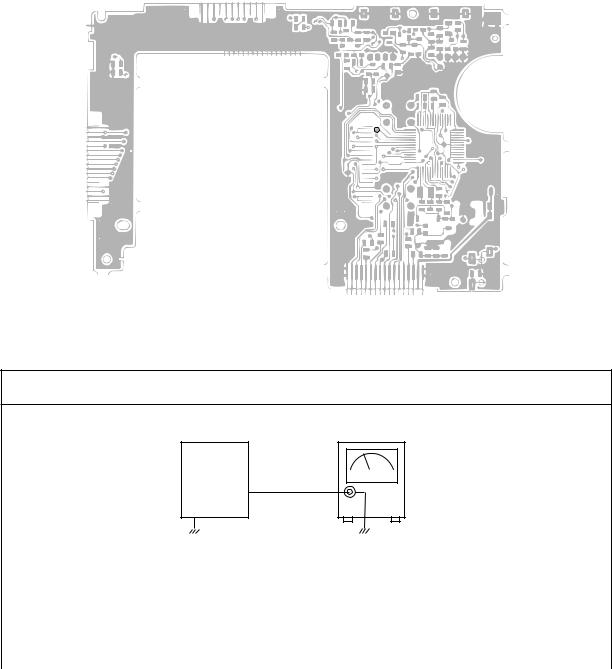
Adjustment And Test Point Locations
TOP VIEW
TP6

 VR700
VR700


Equipment Connection / Procedure
|
Clock Adjustment |
TV-600 |
Voltmeter |
Set |
|
|
Output |
|
TP6 |
|
|
|
|
|
|
|
|
|
|
|
|
|
|
|
|
|
|
|
|
|
|
|
|
|
|
|
|
|
|
|
|
|
|
|
|
|
|
|
|
|
|
|
|
|
|
|
|
|
|
|
|
Input |
Input |
|
Input |
|
Adjust |
Output |
Output |
|
Result |
||||||
Connection |
Point |
|
Signal |
|
Connection |
Point |
|
|||||||||
|
|
|
|
|
|
|
|
|
|
|
|
|
|
|
|
|
|
|
|
|
|
|
|
|
|
|
|
VR700 |
Voltmeter |
TP6 |
Adjust for 2.05 ± 0.05 V read- |
||
|
|
|
|
|
|
|
|
|
|
|
ing |
on voltmeter. |
||||
|
|
|
|
|
|
|
|
|
|
|
|
|
|
|
||
|
|
|
|
|
|
|
|
|
|
|
|
|
|
|
|
|
— 9 —
 Loading...