


VZ-8M
niGITAL
SYNTHESIZER
OPERATION
MANUAL
1
MANUAL
DE
OPERACION
117
r
DIGITAL
SYNTHESIZER
tern,
manual
highly
innovative
digital
ition)
Modular
Sound
Source
sys-
im
your
new
VZ-8M,
be
sure
to
read
this
often.
r
CAUTION
RISK
OF
ELECTRIC
SHOCK
DO
NOT
OPEN
CAUTION:
to
reduce
the
risk
of
electric
SHOCK,
DO
NOT
REMOVE
COVER
(OR
BACK).
NO
USER-SERVICEABLE
PARTS
INSIDE.
REFER
SERVICING
TO
QUALIFIED
SERVICE
PERSONNEL."
CONTENTS
4
Main
Features
6
About
this
Manual
7
Important
Terms
9
Theory:
Flow
of
Operations
13
Theory:
iPD
Modular
Sound
System
17
Operating
System
Controls
19
Menus
and
Functions
20
About
Function
Indexes
21
Function
Index
Practice
Exercise
25
Function
Index
25
VOICE
PARAMETER
menu
45
EFFECT
menu
67
OPERATION
MEMORY
EFFECT
menu
69
TOTAL
CONTROL
menu
76
Performance/Editing
in
the
Normal
Mode
78
Performance/Editing
in
the
Combination
Mode
80
Performance/Editing
in
the
Operation
Memory
Mode
82
Performance/Editing
in
the
Multi
Channel
Mode
84
MIDI
—
Musical
Instrument
Digital
Interface
86
Initializing
the
VZ-8M
87
VZ
Sound
Seminar:
The
elements
of
sound
synthesis
93
Initialized
Data
101
OPERATION
MEMORY
NAMES/VOICE
NAMES
108
Care
of
Your
Unit
109
Features
and
Functions
113
Specifications
ng
flash
with
arrowhead
symbol,
within
an
equilateral
intended
to
alert
the
user
to
the
presence
of
unin-
j'd^ngerous
voltage"
within
the
product's
enclosure
that
ipf
sufficient
magnitude
to
constitute
a
risk
of
electric
persons.
exclamation
point
within
an
equilateral
triangle
is
intended
alert
the
user
to
the
presence
of
important
operating
and
intenance
(servicing)
instructions
in
the
literature
accom-
ing
the
product.
Main
Features
A
Amazing
Synthesis
Versatility
Thanks
to
Casio's
All-new
iPD
Sound
Source
Casio's
all-new
"Interactive
Phase
Distortion"
(iPD)
sound
source
system
actually
consists
of
8
independent
"mod
ules"
(Ml
to
M8).
Each
of
these
modules
contains
a
DCO
and
a
DCA,
and
is
capable
of
generating
independent
waveforms.
In
the
iPD
system,
the
wave
generated
by
any
module
can
be
used
in
either
of
two
ways;
to
produce
audible
sounds
or
to
modify
waves
generated
by
other
modules.
The
8
iPD
sound
source
modules
work
in
associated
pairs
that
are
called
"Internal
Lines,"
or
simply
"lines."
There
are
4
internal
lines
—
A,
B,
C
and D.
The
waveforms
generated
by
both
modules
in
any
line
can
be used
together
in
three
different
ways.
They
can
be
mixed,
or
one
of
the
waveforms
can
be
used
to
modulate
the
other
for
RING
modulation
or
as
the
PHASE
of
a
succeeding
line.
Z*
Instant
Recall
of
up
to
320
Sounds
and
320
Operation
Memories
128
presets
give
you
a
wide
range
of
vocal
versatility.
And
with
the
use
of
an
optional
ROM
card,
the
VZ-8M
gives
you
incredible
tonal
expansion
potential
—
up
to
128
patches
and
128
multi-patch
setups
are
literally
at
your
finger
tips.
What's
more,
you
can
store
up
to
64
sounds
and
64
operation
memories
on
on-board
memory
or
an
optional
RAM
card,
for
even
greater
freedom
of
timbral
expression.
Player-selectable
Keyboard,
Guitar
&
Wind
MIDI
Performance
Modes
The
VZ-8M
lets
you
select
from
3
different
MIDI
performance
modes,
according
to the
type
of
MIDI
controller
you're
using.
Just
select
a
sound
and
choose
the
performance
mode
—
the
"K"
performance
mode
arranges
sounds
in
full
polyphony,
for
realistic
keyboard
performance.
The
"G"
performance
mode
lets
you
play
the
same
sound
in
mono,
emulating
the
individual
strings
of
a
guitar,
while
the
"W"
performance
mode
provides
the
natural
after-touch
charac
teristics
necessary
for
playing
with
wind
controllers.
Multi-Channel
MIDI
Performance
The
VZ-8M
features
Casio's
exclusive
multi-channel
mode
which
can
accept
up
to
8
timbres
from
separate
MIDI
sound
sources.
These
can
then
be
divided
into
constituent
polyphonies
and
ensembled
in
any
format
you
desire.
Multi-
timbral
MIDI
expansion,
monophonic
MIDI
performance,
or
total
8-note
MIDI
polyphony
can
be
selected.
Jj^
Built-in
Panning
Function
The
VZ-8M's
built-in
panning
function
lets
you
choose
from
three
different
panning
effects;
Fixed
panning,
Con
trolled
panning
and
Auto
panning.
Each
panning
effect
adds
spacial
realism
and
ambience
to
your
sound.
U
"Player-friendly"
Menus
and
Functions
Virtually
all
of
the
VZ-8M's
editing
and
programming
operations
are
organized
into
three basic
menus
—
the
VOICE
PARAMETER
menu,
EFFECT
menu
and
TOTAL
CONTROL
menu
—
that
feature
a
variety
of
"functions."
Each
of
these
functions
is
further
broken
down
into
"parameters,"
which
are
constants
that
have
changeable
values
or
settings.
To
alter
sounds
or
programming,
you
simply
alter
the
value
of
these
parameters
using value
keys.
/
Combination
Mode
Provides
Layered
and
Split
Voicing
The
VZ-8M's
"Combination"
mode
lets
you
mix
together
up
to
8
different
patches
in
any
of
9
different
patch
mix
or
patch
split
configurations.
(1
+
2,
3
+
4,
1
+
2
+
3
+
4,
1+2+3
+
4
+
5
+
6+7
+
8,
1/3,
1
+
2/3,
1/3
+
4,
1+2/3+4,
1/2/3/4)
You
can
set
effect
and
amp
levels
independently
for
each
patch.
8
Velocity
Split
&
Positional
Cross
Fade
The
VZ-8M
puts
powerful
multi-voice
performance
in
your
hands,
with
advanced
features
such
as
velocity
split
and
positional
cross
fade.
Set
up
multi-layered
voices
with
up
to
3
split
points,
and
"fade"
the
voices
into
one
another
so
there's
no
audible
"split
point"
with
the
cross
fade
function,
or
control
multiple
voices
through
velocity
message
using
velocity
split.
y
Optional
ROM
&
RAM
Cards
Choose
from
optional
ROM
or
RAM
cards
for
expanded
sound
storage
and
recall
capabilities.
Each
ROM
card
holds
an
impressive
128
patches
and
128
different
operation
memories.
With
a
RAM
card,
you
can
store
up
to
64
patches
and
64
operation
memories.
What's
more,
VZ-8M
patches
can
be
used
in
a
Casio
PG
series
guitar
synth.
Whil.
tal
sy
it
do
a
ref«
Whei
to
co
MID
Once
need
"The
with
Semi:
Next.
throu
Whei
capal
Be
su
will
*
The!
Fort
Most
you'l
own
About
this
Manual
H
While
you
may
not
realize
it
quite
yet,
this
unit
is
an
incredibly
complex
digi
tal
synthesizer
that
has
a
lot
more
in
common
with
a
personal
computer
than
it
does
an
"electronic"
musical
instrument.
This
manual
is
intended
only
as
a
reference
to
provide
instructions
on
the
most
basic
operations.
When
you
take
the
unit
out
of
its
box
for
the
first
time,
you'll
probably
want
to
connect
it
to
an
external
keyboard,
guitar
or
wind
controller
equipped
with
MIDI
and
plug
it
in
immediately
to
see
how
it
sounds.
Once
you're
ready
to
begin
studying
the
true
power
of
this
synth
module,
you'll
need
to
have
a
basic
knowledge
of
its
iPD
modular
sound
source
system.
Read
"Theory:
iPD
Modular
Sound
System"
thoroughly
—
if
you're
not
familiar
with
basic
sound
synthesis
terms
and
theory,
be
sure
to
study
the
"VZ
Sound
Seminar"
as
well.
Next,
you
should
familiarize
yourself
with
the operating
system
controls.
Read
through
the
"Operating
System
Controls"
for
an
introduction
to
these
controls.
When
you're
ready
to
start
using
the
advanced
editing
and
sound
data
storage
capabilities,
you'll
need
to
learn
how
to
use
the
"FUNCTION
INDEXES".
Be
sure
to
work
through
the
"Function
Index
Practice
Exercise"
as
well.
These
will
give
you
a
fairly
solid
understanding
of
basic
synthesis
operations.
The
FUNCTION
INDEXES
will
be
an
invaluable
aid
in
all
editing
operations.
For
this
reason,
be
sure
to
keep
this
manual
handy
whenever
editing
sounds.
Most
importantly,
remember
that
this
manual
is
meant
as
a
reference
only
—
you'll
only
be
able to
realize
the
true
power
of
this
unit
as
you
apply
it
to
your
own
musical
performance.
Important
Terms
Throughout
this
manual
you
will
encounter
terms
(words)
which
you
may
—
or
may
not
—
be
familiar
with.
Before
jumping
into
the
operations,
it's
important
to
make
sure
that
you
understand
the
basic
usage
of
these
terms
in
this
manual.
Take
a
few
moments
to
read
through
these
words
and
become
familiar
with
them
—
you'll
find
it
will
enhance
your
over
all
understanding
of
this
unit.
Jl
MENU
FUNCTION
PARAMETER
VALUE
MODULE
INTERNAL
LINE
EXTERNAL
PHASE
PATCH
OPERATION
MEMORY
ENVELOPE
MODE
A
displayed
list
of
the
various
FUNCTIONS
you
can
use
to
edit
sounds.
There
are
three
basic
Menus
which
can
be
selected;
the
VOICE
PARAMETER
menu
(VOICE
menu),
EFFECT
menu,
and
TOTAL
CONTROL
menu
(TOTAL
menu).
Any
of
the
items
listed
on
the
menus.
Each
Function
contains
a
variety
of
PARAMETERS,
and
is
identified
by
a
two-digit
number.
For
example,
Function
02
in
VOICE
PARAMETER
menu
contains
parameters
related
to
detuning.
A
constant
control
which
features
variable
levels.
These
parameters
control
not
only
data
that
affects
the
various
components
of a
sound,
but
also
aspects
of
the
overall
setup.
The
level
or
setting
assigned
to
an
individual
parameter.
The
iPD
sound
source
features
8
independent
"modules."
These
can
be
thought
of
as
independent
—
but
interrelated
—
oscillators
with
controls.
Sound
source
MODULES
work
together
in
"pairs."
These
pairs
form
what
is
known
as
an
INTERNAL
LINE,
or
simply
"line."
For
example,
Module
1
and
Module
2
(Ml
and
M2)
form
Internal
Line
A
—
known
in
this
manual
as
LINE
A.
M3
and
M4
form
LINE
B,
etc.
In
addition
to
using
the
output
of
any
LINE
to
create
audible
sounds,
you
can
uti
lize
the
output
to
modulate
the
succeeding
line.
For
example,
the
output
of
LINE
A
can
be
used
to
modulate
LINE
B.
This
configuration
is
known
as
"External
Phase."
(Refer
to
"Theory:
iPD
Modular
Sound
System"
for
details.)
With
analog
synthesizers,
a
"patch"
literally
referred
to
the
way
in
which
various
synthesizer
blocks
or
modules
were
hard-wired
(hooked
up).
With
digital
synthesizers,
this
term
has
come
to
refer
to
completed
sound
data
which
can
be
output
by
the
synthesizer.
In
this
manual,
you
can
think
of
"patch"
as
referring
to
any
complet
ed
sound
data
coming
from
modules
1
through
8.
An
operation
memory
is
literally
a
full
"multi-timbral
setup"
or
"performance
setup",
complete
with
specifications
for
multiple
patches
(when
desired),
keyboard
and
velocity
split,
MIDI
settings,
etc.
The
onboard
memory
allows
storage
of
128
preset
operation
memories.
A
voltage
which
changes
as
a
function
of
time.
Envelopes
are
generally triggered
by
controllers,
and
are
used
to
shape
the
amplitude
(volume)
and
pitch
of
a
note.
A
particular
operational
function
or
condition.
In
"VZ
language",
there
are
4
bas
ic
operational
modes,
including
the
NORMAL
mode,
the
COMBINATION
mode,
the
OPERATION
MEMORY
mode, and
the
MULTI
CHANNEL
mode.
Each
of
these
serves
an
independent
purpose
described
later in this
manual.
PERFORMANCE
MODE
KMODE
GMODE
WMODE
VOICE-09
EFFECT-05
CONTROL-04
OPE
EFFECT
PROG
NO
KEYS
MOD
WHEEL
DEF
CONTROL
PAGE
KEYS
COMBI
MODE
MULTI
CH
MODE
M
ON/OFF
KEY
There
are
3
basic
"MIDI
Performance
Modes",
which
should
not
be
confused
with
the
basic
operational
"modes".
The
"Performance
Modes"
are
actually preset
parameter
setups
programmed
for
each
sound
individually,
which
can
be
selected
to
"match"
the
selected
sound
with
the
type
of
MIDI
controller
you
are
using.
For
example,
if
you're
using
a
MIDI
keyboard,
you'll
want
to
select
the
"K"
or
key
board
performance
mode.
In
addition
to
"K",
there
are
"G"
(Guitar)
and
"W"
(Wind)
MIDI
performance
modes.
Short
for
"Keyboard
Mode"
—
one
of
three
VZ-8M
MIDI
performance
modes.
Short
for
"Guitar
Mode"
—
one
of
three
VZ-8M
MIDI
performance
modes.
Short
for
"Wind
Mode"
—
one
of
three
VZ-8M
MIDI
performance
modes.
Throughout
this
text,
the
names
of
each
of
the
three
main
"menus"
is
listed
in
cap
ital
letters.
In
this
case,
VOICE-09
indicates
function
"09"
in
the
"Voice
Parameter"
menu
—
the
"AMP
ENV"
function.
Throughout
this
text,
the
names
of
each
of
the
three
main
"menus"
is
listed
in
cap
ital
letters.
In
this
case,
EFFECT-05
indicates
function
"05"
in
the
"Effect"
menu
—
the
"DEF
CONTROL"
function.
Throughout
this
text,
the
names
of
each
of
the
three
main
"menus"
is
listed
in
cap
ital
letters.
In
this
case,
CONTROL-04
indicates
function
"04"
in
the
"Total
Con
trol"
menu
—
the
"MIDI
CHANNEL"
function.
Indicates
the
EFFECT
menu
in
the
OPERATION
MEMORY
mode.
For
example,
"OPE
EFFECT-01"
represents
function
"01"
in
the
OPERATION
MEMORY
mode's
EFFECT
menu
—
the
"OP
TUNE"
function.
Short
for
"Program
Number
Keys".
These
keys
are
used
in
a
variety
of
sound
syn
thesis
and
editing
operations.
Short
for
"Modulation
Wheel".
Short
for
"Definable
Control".
Used
to
"scroll"
or
advance
up
and
down
the
selected
VZ
menu.
Short
for
"Combination
Mode"
—
one
of
the
4
basic
operational
modes
used
in
synthesis,
editing
and
performance.
Short
for
"Multi
Channel
Mode"
—
another
of
the
basic
operational
modes.
Short
for
"Module
ON/OFF
Key"
—
keys
used
to
turn
the
VZ's
sound
source
mod
ules
ON
and
OFF.
Theory:
Flow
of
Operations
ji
Although
the
VZ-8M
features
a
complex
operating
system,
it
has
been
designed
so
that
actual
operations
are
quite
simple
—
after
a
few
hours
you'll
be
amazed
at
how
simple
the
unit
is
to
operate,
and
how
versatile
it
is.
In
order
to
appreciate
the
beauty
of
the
VZ,
it's
important
to
have
a
clear
initial
understanding
of
its
basic
"flow
of
operations"
—
in
other
words
the
basic
order
of
operations
you
will
probably
want
to
follow
to
make
the
most
of
this
synthesizer.
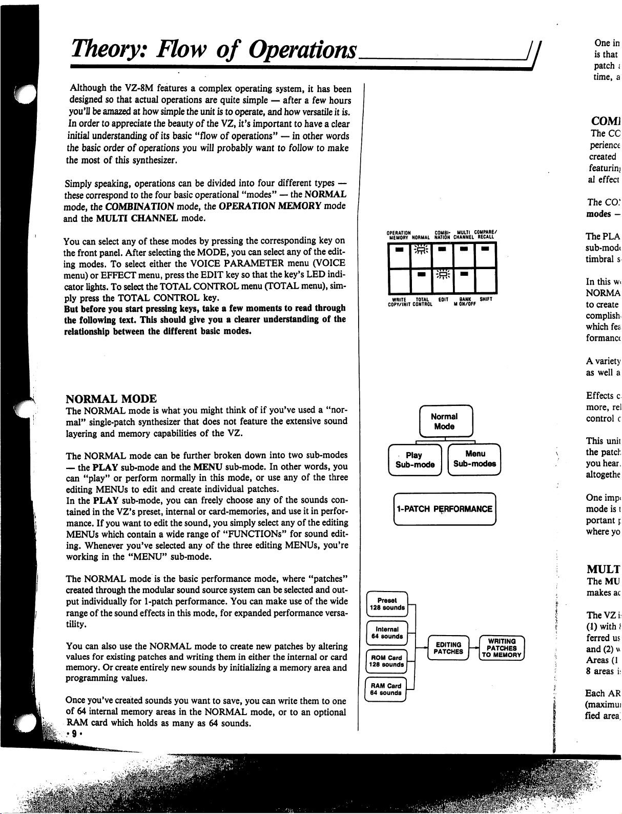
Simply
speaking,
operations
can
be
divided
into
four
different
types
—
these
correspond
to
the
four
basic
operational
"modes"
—
the
NORMAL
mode,
the
COMBINATION
mode,
the
OPERATION
MEMORY
mode
and
the
MULTI
CHANNEL
mode.
You
can
select
any
of
these
modes
by
pressing
the
corresponding
key
on
the
front
panel.
After
selecting
the
MODE,
you
can
select
any
of
the
edit
ing
modes.
To
select
either
the
VOICE
PARAMETER
menu
(VOICE
menu)
or
EFFECT
menu,
press
the
EDIT
key
so
that
the
key's
LED
indi
cator
lights.
To
select
the
TOTAL
CONTROL
menu
(TOTAL
menu),
sim
ply
press
the
TOTAL
CONTROL
key.
But
before
you
start
pressing
keys,
take
a
few
moments
to
read
through
the
following
text.
This
should
give
you
a
clearer
understanding
of
the
relationship
between
the
different
basic
modes.
NORMAL
MODE
The
NORMAL
mode
is
what
you
might
think
of
if
you've
used
a
"nor
mal"
single-patch
synthesizer
that
does
not
feature
the
extensive
sound
layering
and
memory
capabilities
of
the
VZ.
The
NORMAL
mode
can be
further
broken
down
into
two
sub-modes
—
the
PLAY
sub-mode
and
the
MENU
sub-mode.
In
other
words,
you
can
"play"
or
perform
normally
in
this
mode,
or
use
any
of
the
three
editing
MENUs
to
edit
and
create
individual patches.
In
the
PLAY
sub-mode,
you
can
freely
choose
any
of
the
sounds
con
tained
in
the
VZ's
preset,
internal
or
card-memories,
and
use
it
in
perfor
mance.
If
you
want
to
edit
the
sound,
you
simply
select
any
of
the
editing
MENUs
which
contain
a
wide
range
of
"FUNCTIONS"
for
sound
edit
ing.
Whenever
you've
selected
any
of
the
three
editing
MENUs,
you're
working
in
the
"MENU"
sub-mode.
The
NORMAL
mode
is
the
basic
performance
mode,
where
"patches"
created
through
the
modular
sound
source
system
can
be
selected
and
out
put
individually
for
1-patch
performance.
You
can
make
use
of
the
wide
range
of
the
sound
effects in
this
mode,
for
expanded
performance
versa
tility.
You
can
also
use
the
NORMAL
mode
to
create
new
patches
by
altering
values
for
existing
patches
and
writing
them
in
either
the
internal
or card
memory.
Or
create
entirely
new
sounds
by
initializing
a
memory
area
and
programming
values.
Once
you've
created
sounds
you
want
to
save,
you
can
write
them
to
one
of
64
internal
memory
areas
in
the
NORMAL
mode,
or
to
an
optional
RAM
card
which
holds
as
many
as
64
sounds.
WRITE
TOTAL
EOIT
BANK
SHIFT
COPY/INIT
CONTROL
M
ON/OFF
WRITING
PATCHES
TO
MEMORY
f
RE/
•LL
JfPV
f
WRITING
PATCHES
0
MEMORY
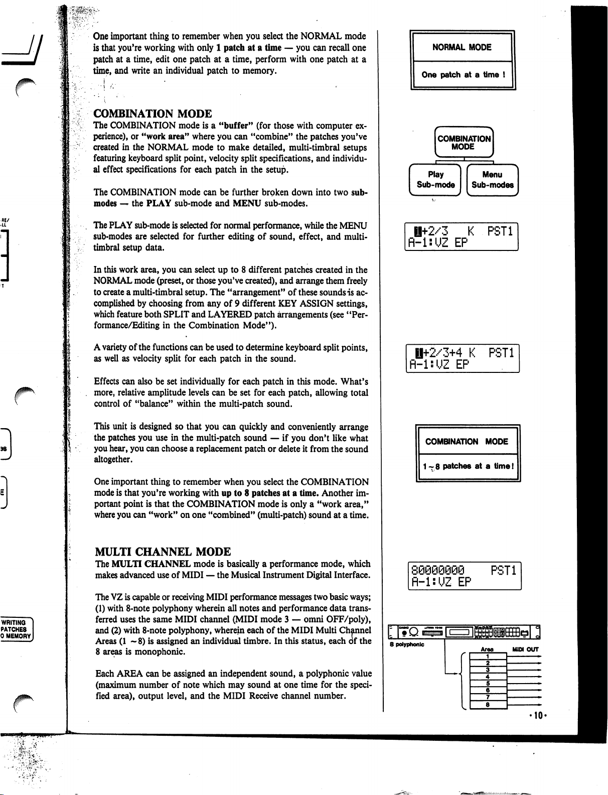
One
important
thing
to
remember
when
you
select
the
NORMAL
mode
is
that
you're
working
with
only
1
patch
at
a
time
—
you
can
recall
one
patch
at
a
time,
edit
one
patch
at
a
time,
perform
with
one
patch
at
a
time,
and
write
an
individual
patch
to
memory.
COMBINATION
MODE
The
COMBINATION
mode
is
a
"buffer"
(for
those
with
computer
ex
perience),
or
"work
area"
where
you
can
"combine"
the
patches
you've
created
in
the
NORMAL
mode
to
make
detailed,
multi-timbral
setups
featuring
keyboard
split
point,
velocity
split
specifications,
and
individu
al
effect
specifications
for
each
patch
in
the
setup.
The
COMBINATION
mode
can
be
further
broken
down
into
two
sub-
modes
—
the
PLAY
sub-mode
and
MENU
sub-modes.
The
PLAY
sub-mode
is
selected
for
normal
performance,
while
the
MENU
sub-modes
are
selected
for
further
editing
of
sound,
effect,
and
multi-
timbral
setup
data.
In
this
work
area,
you
can
select
up
to
8
different
patches
created
in
the
NORMAL
mode
(preset,
or
those
you've
created),
and
arrange
them
freely
to
create
a
multi-timbral
setup.
The
"arrangement"
of
these
sounds
is
ac
complished
by
choosing
from
any
of 9
different
KEY
ASSIGN
settings,
which
feature
both
SPLIT
and
LAYERED
patch
arrangements
(see
"Per
formance/Editing
in
the
Combination
Mode").
A
variety
of
the
functions
can
be
used
to
determine
keyboard
split
points,
as
well
as
velocity
split
for
each
patch
in
the
sound.
Effects
can
also
be
set
individually
for
each
patch
in
this
mode.
What's
more,
relative
amplitude
levels
can
be
set
for
each
patch,
allowing
total
control
of
"balance"
within
the
multi-patch
sound.
This
unit
is
designed
so
that
you
can
quickly
and
conveniently
arrange
the
patches
you
use
in
the
multi-patch
sound
—
if
you
don't
like
what
you
hear,
you
can
choose
a
replacement
patch
or
delete
it
from
the
sound
altogether.
One
important
thing
to
remember
when
you
select
the
COMBINATION
mode
is
that
you're
working
with
up
to
8
patches
at
a
time.
Another
im
portant
point
is
that
the
COMBINATION
mode
is
only
a
"work
area,"
where
you
can
"work"
on
one
"combined"
(multi-patch)
sound
at
a
time.
MULTI
CHANNEL
MODE
The
MULTI
CHANNEL
mode
is
basically
a
performance
mode,
which
makes
advanced
use
of
MIDI
—
the
Musical
Instrument
Digital
Interface.
The
VZ
is
capable
or
receiving
MIDI
performance
messages
two
basic
ways;
(1)
with
8-note
polyphony
wherein
all
notes
and
performance
data
trans
ferred
uses the
same
MIDI
channel
(MIDI
mode
3
—
omni
OFF/poly),
and
(2)
with
8-note
polyphony,
wherein
each
of
the
MIDI
Multi
Channel
Areas
(1
—8)
is
assigned
an
individual
timbre.
In
this
status,
each
of
the
8
areas
is
monophonic.
Each
AREA
can
be
assigned
an
independent
sound,
a
polyphonic
value
(maximum
number
of
note
which
may
sound
at
one
time
for
the
speci
fied
area),
output
level,
and
the
MIDI
Receive
channel
number.
NORMAL
MODE
One
patch
at
a
time
!
combination]
MODE
I
Ii+2/3
K
PST1
R-l:UZ
EP
H+2/3+4
K
PST1
fl-UUZ
EP
COMBINATION
MODE
1-8
patches
at
a
time!
fl-l:UZ
EP
PST1
8
polyphonic
Area
MUM
OUT
r
OPERATION
MEMORY
MODE
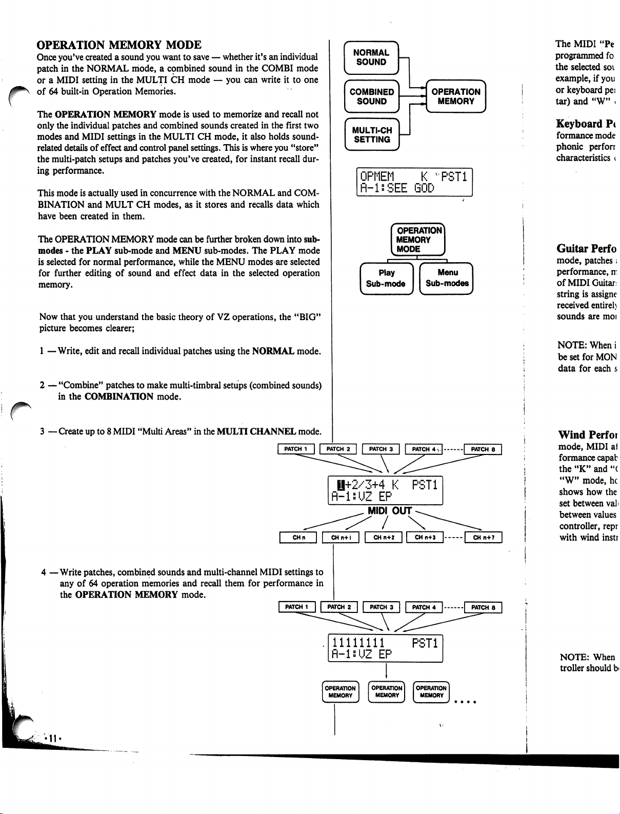
Once
you've
created
a
sound
you
want
to
save
—
whether
it's
an
individual
patch
in
the
NORMAL
mode,
a
cpmbined
sound
in
the
COMBI
mode
or
a
MIDI
setting
in
the
MULTI
CH
mode
—•
you
can
write
it
to
one
of
64
built-in
Operation
Memories.
The
OPERATION
MEMORY
mode
is
used
to
memorize
and
recall
not
only
the
individual
patches
and
combined
sounds
created
in
the
first
two
modes
and
MIDI
settings
in
the
MULTI
CH
mode,
it
also
holds
sound-
related
details
of
effect
and
control
panel
settings.
This
is
where
you
"store"
the
multi-patch
setups
and
patches
you've
created,
for
instant
recall
dur
ing
performance.
This
mode
is
actually
used
in
concurrence
with
the
NORMAL
and
COM
BINATION
and
MULT
CH
modes,
as
it
stores
and
recalls
data
which
have
been
created
in
them.
The
OPERATION
MEMORY
mode
can
be
further
broken
down
into
sub-
modes
-
the
PLAY
sub-mode
and
MENU
sub-modes.
The
PLAY
mode
is
selected
for
normal
performance,
while
the
MENU
modes
are
selected
for
further
editing
of
sound
and
effect
data
in
the
selected
operation
memory.
Now
that
you
understand
the
basic
theory
of
VZ
operations,
the
"BIG"
picture
becomes
clearer;
1
—Write,
edit
and
recall
individual
patches
using
the
NORMAL
mode.
r
2
—
"Combine"
patches
to
make
multi-timbral
setups
(combined
sounds)
in
the
COMBINATION
mode.
3
—
Create
up
to
8
MIDI
"Multi
Areas"
in
the
MULTI
CHANNEL
mode.
|
PATCH
1
| |
PATCH
2
|
|
PATCH
3
|
|
PATCH
4
. | |
PATCH
8
|
0+2/3+4
K
PST1
R-isUZ
EP
MIDI
OUT
/
4
—Write
patches,
combined
sounds
and
multi-channel
MIDI
settings
to
any
of
64
operation
memories
and
recall
them
for
performance
in
the
OPERATION
MEMORY
mode.
CHn
CHn+l
CH
n+2
|
PATCH
1
|
|
PATCH
2
|
|
PATCH
3
| |
PATCH
4
|
|
PATCH
8
11111111
PST1
fl-ls'JZ
EP
The
MIDI
"Pe
programmed
fo
the
selected
soi
example,
if
you
or
keyboard
pei
tar)
and
"W"
»
Keyboard
Pc
formance
mode
phonic
perforr
characteristics
i
Guitar
Perf
o
mode,
patches;
performance,
rr
of
MIDI
Guitar,
string
is
assigne
received
entireh
sounds
are
moi
NOTE:
When
i
be
set
for
MON
data
for
each
s
Wind
Perfor
mode,
MIDI
af
formance
capab
the
"K"
and
"(
"W"
mode,
he
shows
how
the
set
between
val>
between
values
controller,
repr
with
wind
instr
NOTE:
When
troller
should
b<
/0^\
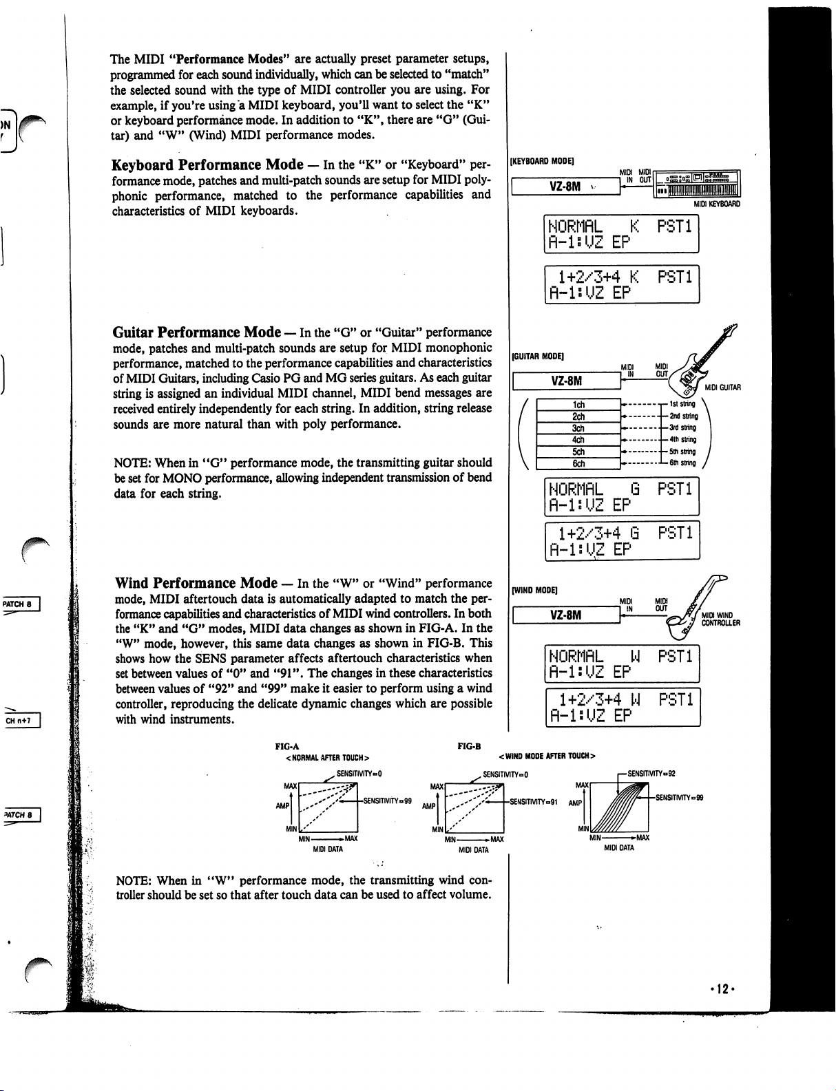
The
MIDI
"Performance
Modes"
are
actually
preset
parameter
setups,
programmed
for
each
sound
individually,
which
can
be
selected
to
"match"
the
selected
sound
with
the
type
of
MIDI
controller
you
are
using.
For
example,
if
you're
using
"a
MIDI
keyboard,
you'll
want
to
select
the
"K"
or
keyboard
performance
mode.
In
addition
to
"K",
there
are
"G"
(Gui
tar)
and
"W"
(Wind)
MIDI
performance
modes.
Keyboard
Performance
Mode
—
In
the
"K"
or
"Keyboard"
per
formance
mode,
patches
and
multi-patch
sounds
are
setup
for
MIDI
poly
phonic
performance,
matched
to
the
performance
capabilities
and
characteristics
of
MIDI
keyboards.
Guitar
Performance
Mode
—
In
the
"G"
or
"Guitar"
performance
mode,
patches
and
multi-patch
sounds
are
setup
for
MIDI
monophonic
performance,
matched
to
the
performance
capabilities
and
characteristics
of
MIDI
Guitars,
including
Casio
PG
and
MG
series
guitars.
As
each
guitar
string
is
assigned
an
individual
MIDI
channel,
MIDI
bend
messages
are
received
entirely
independently
for
each
string.
In
addition,
string
release
sounds
are
more
natural
than
with
poly
performance.
NOTE:
When
in
"G"
performance
mode,
the
transmitting
guitar
should
be
set
for
MONO
performance,
allowing
independent
transmission
of
bend
data
for
each
string.
Wind
Performance
Mode
—
In
the
"W"
or
"Wind"
performance
mode,
MIDI
aftertouch
data
is
automatically
adapted
to
match
the
per
formance
capabilities
and
characteristics
of
MIDI
wind
controllers.
In
both
the
"K"
and
"G"
modes,
MIDI
data
changes
as
shown
in
FIG-A.
In
the
"W"
mode,
however,
this
same
data
changes
as
shown
in
FIG-B.
This
shows
how
the
SENS
parameter
affects
aftertouch
characteristics
when
set
between
values
of
"0" and
"91".
The
changes
in
these
characteristics
between
values
of
"92"
and
"99"
make
it
easier
to
perform
using
a
wind
controller,
reproducing
the
delicate
dynamic
changes
which
are
possible
with
wind
instruments.
FIG-A
<
NORMAL
AFTER
TOUCH
>
FIG-B
[KEYBOARD
MODE]
VZ-8M
MIDI
KEYBOARD
NORMflL
K
PST1
fl-lsUZ
EP
1+2/3+4
K
R-isUZ
EP
PST1
(GUITAR
MODE]
VZ-8M
MIDI
GUITAR
--1ststring
\
--2nd
string
\
•
-3rd
string
|
.-4th
string
•-5th
string
/
■•
-6th
string
/
NORMflL
fi-lsUZ
EP
8
PST1
1+2/3+4
G
R-inUZ
EP
PST1
(WIND
MODE]
VZ-8M
NORMflL
W
fl-l:UZ
EP
PST1
1+2/3+4
W
fl-lsUZ
EP
PST1
MAX
AMP
MIN
XSENSITIVITY»O
-SENSmVITY»99
<WIND
MODE
AFTER
TOUCH
>
„
SENSITMTYoO
MAX
AMP
MIN
''''/''<—[-SENSITMTY=91
AMP
MIN
»MAX
MIDI
DATA
MAX
MIN
-MAX
MIDI
DATA
SENSITIVITY»92
•SENSITMTY=99
MIDI
DATA
NOTE:
When
in
"W"
performance
mode,
the
transmitting
wind
con
troller
should
be
set
so
that
after
touch
data
can
be
used
to
affect
volume.
Theory:
iPD
Modular
Sound
System
l
I;!'1
At
the
heart
of
the
VZ's
amazing
sound
synthesis
capabilities
is
an
all-
new
"iPD"
(interactive
Phase
Distortion)
sound
source.
In
order
to
get
the
most
out
of
your
unit,
it
is
vitally
important
that
you
understand
at
least
the
basic
theory
behind
this
new
sound
source.
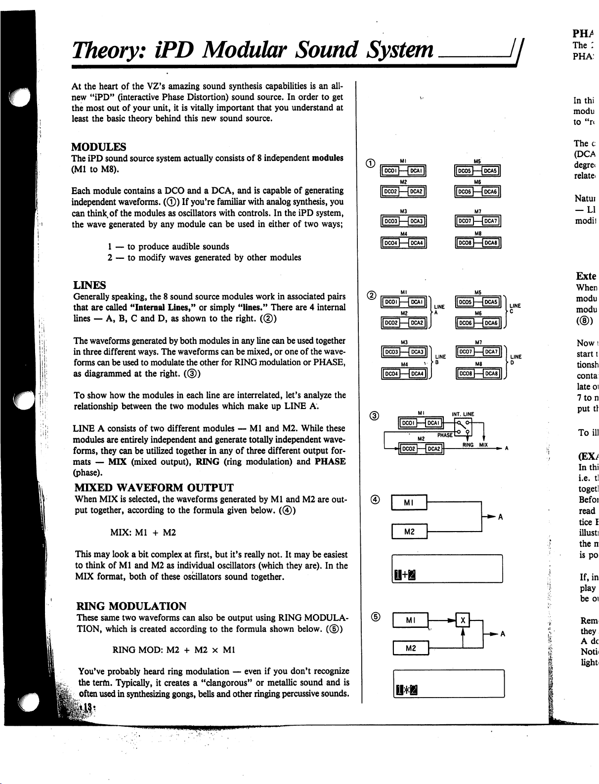
MODULES
The
iPD
sound
source
system
actually
consists
of
8
independent
modules
(Ml
to
M8).
Each
module
contains
a
DCO
and
a
DCA,
and
is
capable
of
generating
independent
waveforms.
(©)
If
you're
familiar
with
analog
synthesis,
you
can
think
of
the
modules
as
oscillators
with
controls.
In
the
iPD
system,
the
wave
generated
by any
module
can
be
used
in
either
of
two
ways;
1
—
to
produce
audible
sounds
2
—
to
modify
waves
generated
by
other
modules
LINES
Generally
speaking,
the
8
sound
source
modules
work
in
associated
pairs
that
are
called
"Internal
Lines,"
or
simply
"lines."
There
are
4
internal
lines
—
A,
B,
C
and
D,
as
shown
to
the
right.
(®)
The
waveforms
generated
by
both
modules
in
any
line
can
be
used
together
in
three
different
ways.
The
waveforms
can
be
mixed,
or
one
of
the
wave
forms
can
be
used
to
modulate
the
other
for
RING
modulation
or
PHASE,
as
diagrammed
at
the
right.
((§))
To
show
how
the
modules
in
each
line
are
interrelated,
let's
analyze
the
relationship
between
the
two
modules
which
make
up
LINE
A.
LINE
A
consists
of
two
different
modules
—
Ml
and
M2.
While
these
modules
are
entirely
independent
and
generate
totally
independent
wave
forms,
they
can
be
utilized
together
in
any
of
three
different
output
for
mats
—
MIX
(mixed
output),
RING
(ring
modulation)
and
PHASE
(phase).
MIXED
WAVEFORM
OUTPUT
When
MIX
is
selected,
the
waveforms
generated
by
Ml
and
M2
are
out
put
together,
according
to
the
formula
given
below.
(©)
MIX:
Ml
+
M2
This
may
look
a
bit
complex
at
first,
but
it's
really
not.
It
may
be
easiest
to
think
of
Ml
and
M2
as
individual
oscillators
(which
they
are).
In the
MIX
format,
both of
these
oscillators
sound
together.
RING
MODULATION
These
same
two
waveforms
can
also
be
output
using
RING
MODULA
TION,
which
is
created
according
to
the
formula
shown
below.
(®)
RING
MOD:
M2
+
M2
x
Ml
You've
probably
heard
ring
modulation
—
even
if
you
don't
recognize
the
term.
Typically,
it
creates
a
"clangorous"
or
metallic
sound
and
is
often
used
in
synthesizing
gongs,
bells
and
other
ringing
percussive
sounds.
■»-
A
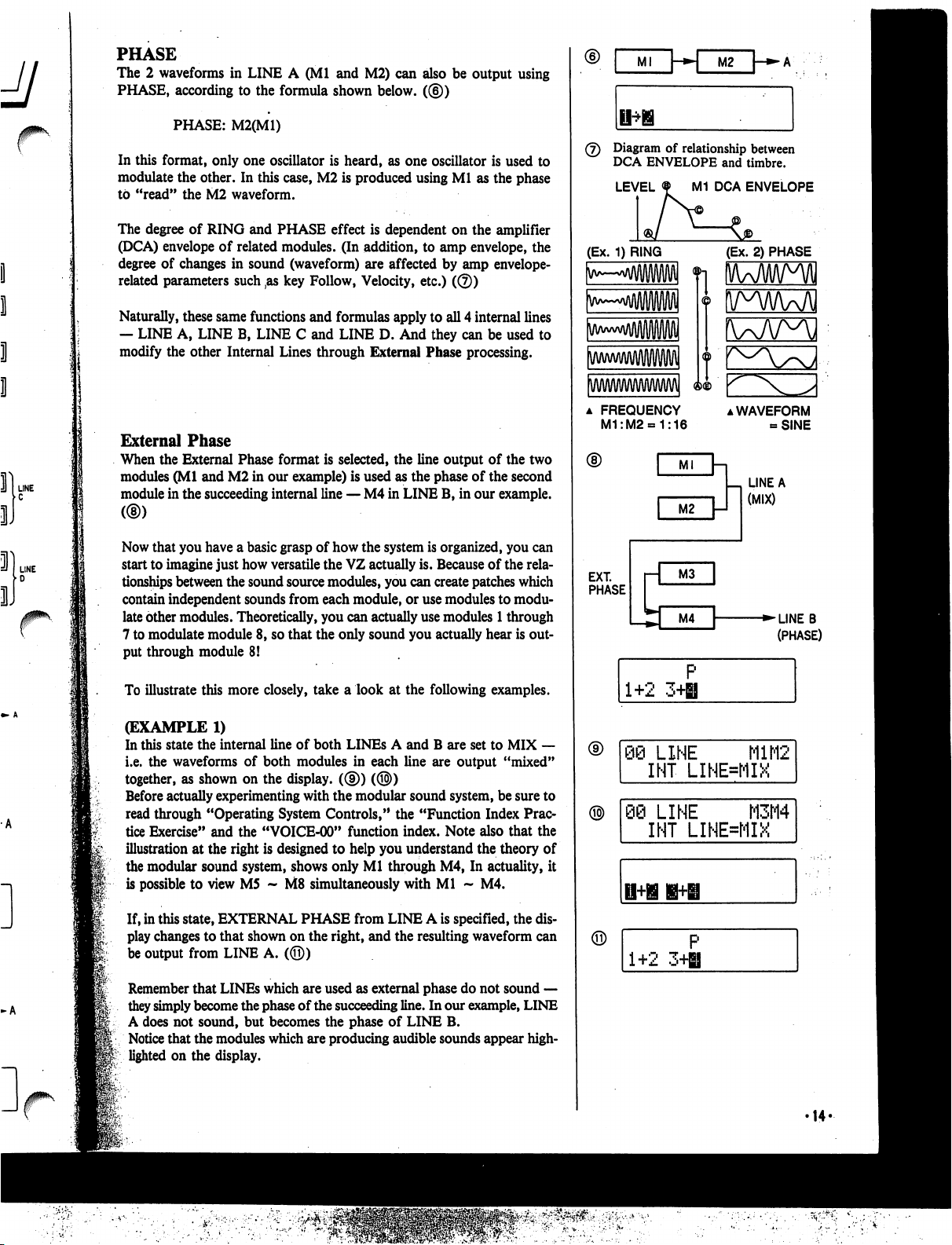
PHASE
The
2
waveforms
in
LINE
A
(Ml
and
M2)
can
also
be
output
using
PHASE,
according
to
the
formula
shown
below.
((§))
PHASE:
M2(M1)
In
this
format,
only
one
oscillator
is
heard,
as
one
oscillator
is
used
to
modulate
the
other.
In
this
case,
M2
is
produced
using
Ml
as
the
phase
to
"read"
the
M2
waveform.
The
degree
of
RING
and
PHASE
effect
is
dependent
on
the
amplifier
(DCA)
envelope
of
related
modules.
(In
addition,
to
amp
envelope,
the
degree
of
changes
in
sound
(waveform)
are
affected
by
amp
envelope-
related
parameters such
,as
key
Follow,
Velocity,
etc.)
(©)
Naturally,
these
same
functions
and
formulas
apply
to
all
4
internal
lines
—
LINE
A,
LINE
B,
LINE
C
and
LINE
D.
And
they
can
be
used
to
modify
the
other
Internal
Lines
through
External
Phase
processing.
External
Phase
When
the
External
Phase
format
is
selected,
the
line
output
of
the
two
modules
(Ml
and
M2
in
our
example)
is
used
as
the
phase
of
the
second
module
in
the
succeeding
internal
line
—
M4
in
LINE
B,
in
our
example.
Now
that
you
have
a
basic
grasp
of
how
the
system
is
organized,
you
can
start
to
imagine
just
how
versatile
the
VZ
actually
is.
Because
of
the
rela
tionships
between
the
sound
source
modules,
you
can
create
patches
which
contain
independent
sounds
from
each
module,
or
use
modules
to
modu
late
other
modules.
Theoretically,
you
can
actually
use
modules
1
through
7
to
modulate
module
8,
so
that
the
only
sound
you
actually
hear
is
out
put
through
module
8!
To
illustrate
this
more
closely,
take
a
look
at
the following
examples.
(EXAMPLE
1)
In
this
state
the
internal
line
of
both
LINEs
A
and
B
are
set
to
MIX
—
i.e.
the
waveforms
of
both
modules
in
each
line
are
output
"mixed"
together,
as
shown
on
the
display.
((§))
(®)
Before
actually
experimenting
with
the
modular
sound
system,
be
sure
to
read
through
"Operating
System
Controls,"
the
"Function
Index
Prac
tice
Exercise"
and
the
"VOICE-00"
function
index.
Note
also that
the
illustration
at
the
right
is
designed
to
help
you
understand
the
theory
of
the
modular
sound
system,
shows
only
Ml
through
M4,
In
actuality,
it
is
possible
to
view
M5
~
M8
simultaneously
with
Ml
~
M4.
If,
in
this
state,
EXTERNAL
PHASE
from
LINE
A
is
specified,
the
dis
play
changes
to that
shown
on
the
right,
and
the
resulting
waveform
can
be
output
from
LINE
A.
(©)
Remember
that
LINEs
which
are
used
as
external
phase
do
not
sound
—
they
simply
become
the
phase
of
the
succeeding
line.
In
our
example,
LINE
A
does
not
sound,
but
becomes
the
phase
of
LINE
B.
Notice
that
the
modules
which
are
producing
audible
sounds
appear
high
lighted
on
the
display.
Ml
\-*»\
M2
(7)
Diagram
of
relationship
between
DCA
ENVELOPE
and
timbre.
LEVEL
M1
DCA
ENVELOPE
(Ex.
1)
RING
(Ex.
2)
PHASE
a
FREQUENCY
M1:M2«=1:16
▲
WAVEFORM
-SINE
LINE
A
(MIX)
EXT.
PHASE
■►LINEB
(PHASE)
1+2
3H
P
Q@
LINE
M1M2
INT
LINE=MIX
)
LINE
M3M4
INT
LINE=MIX
1+2
3+H
'14-
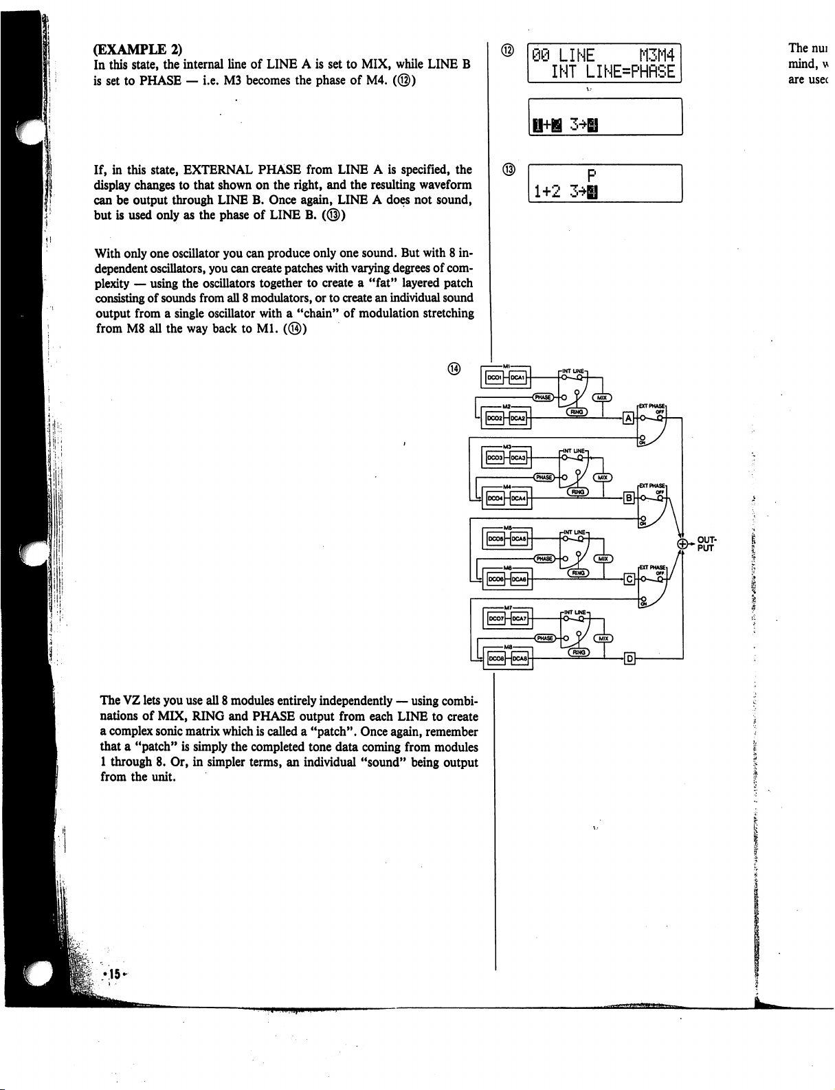
(EXAMPLE
2)
In
this
state,
the
internal
line
of
LINE
A
is
set
to
MIX,
while
LINE
B
is
set
to
PHASE
—
i.e.
M3
becomes
the
phase
of
M4.
(@)
If,
in
this
state,
EXTERNAL
PHASE
from
LINE
A
is
specified,
the
display
changes
to
that
shown
on
the
right,
and
the
resulting
waveform
can
be
output
through
LINE
B.
Once
again,
LINE
A
does
not
sound,
but
is
used
only
as
the
phase
of
LINE
B.
(@)
With
only
one
oscillator
you
can
produce
only
one
sound.
But
with
8
in
dependent
oscillators,
you
can
create
patches
with
varying
degrees
of
com
plexity
—
using
the
oscillators
together
to create
a
"fat"
layered
patch
consisting
of
sounds
from
all
8
modulators,
or
to
create
an
individual
sound
output
from
a
single
oscillator
with
a
"chain"
of
modulation
stretching
from
M8
all
the
way
back
to
Ml.
(@)
09
LINE
M3M4
INT
LINE=PHRSE
The
nui
mind,
u
are
usec
1+2
3*H
The
VZ
lets
you
use
all
8
modules
entirely
independently
—
using
combi
nations
of
MIX,
RING
and
PHASE
output
from
each
LINE
to
create
a
complex
sonic
matrix
which
is
called
a
"patch".
Once
again,
remember
that
a
"patch"
is
simply
the
completed
tone data
coming
from
modules
1
through
8.
Or,
in
simpler
terms,
an
individual
"sound"
being
output
from
the
unit.
•15-
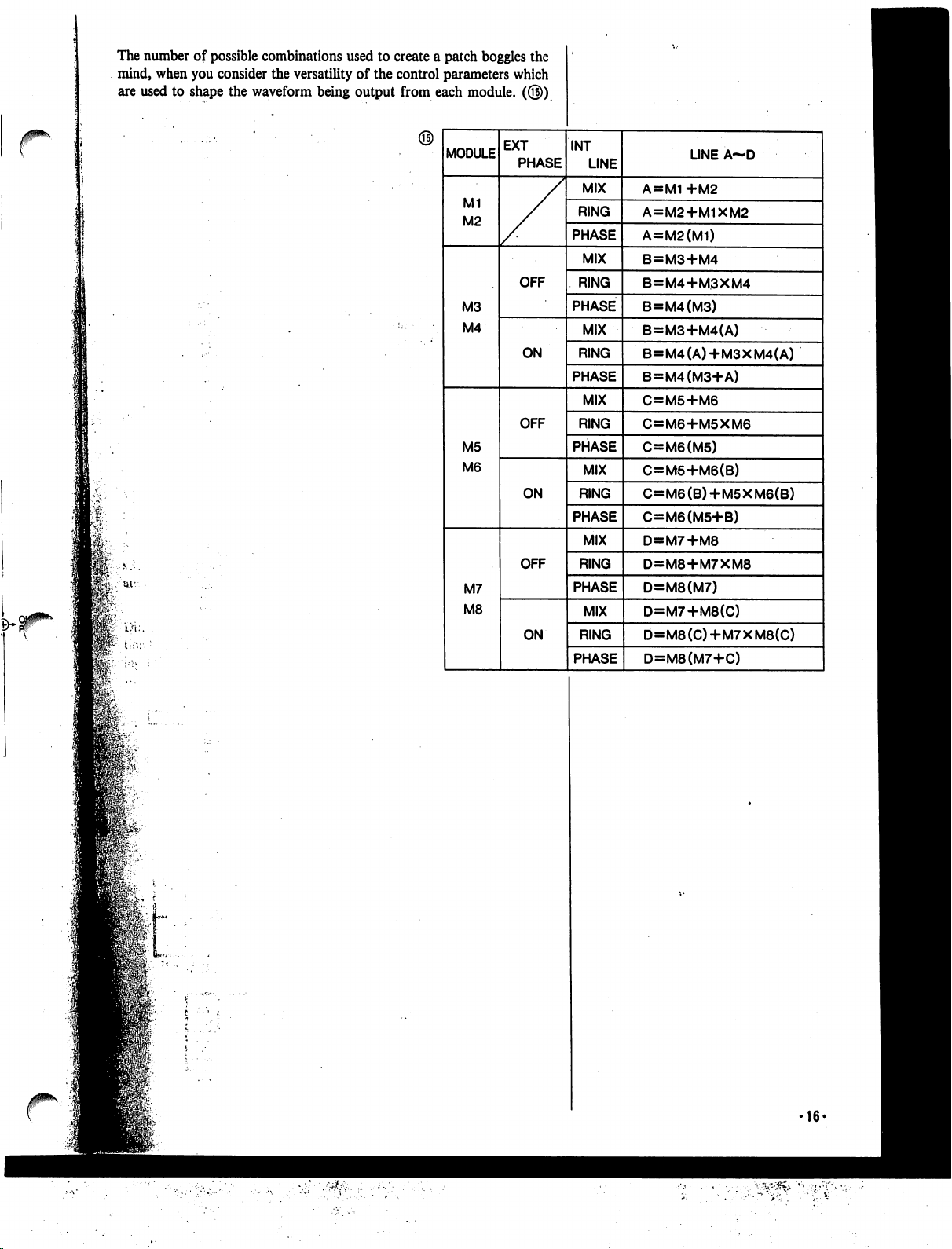
The
number
of
possible
combinations
used
to
create
a
patch
boggles
the
mind,
when
you
consider
the
versatility
of
the
control
parameters
which
are
used
to
shape
the
waveform
being
output
from
each
module.
(©)
16-
Operating
System
Controls.
jj
In
some
ways,
your
VZ
is
very
similar
to
a
computer,
as
it
is
capable
of
storing
and
generating
a
large
amount
of
digital
sound
data.
This
"data
processing"
is
maintained
by
the
"Operating
System,"
which
you
can
think
of
as
a
collection
of
system
programs
that
control
the
overall
operation
of
the
unit.
The
main
interface
with
the
operating
system
can
be
found
in
the
menu
functions.
These
functions
contain
a
number
of
parameters,
which
deter
mine
the
various
characteristics
of
the
sounds.
In
fact,
sound
synthesis
on
the
unit
basically
consists
of
inputting
values
for
these
parameters.
With
a
computer,
you
generally
execute
a
certain
program,
and
use
a
cur
sor
to
move
to
different
positions
in
the
displayed
page,
and
use
the
key
board
to
input
commands,
values,
text,
etc. (this
is,
of
course
a
simplified
explanation.)
Your
unit
works
much
in
the
same
way,
and
it
features
a
number
of
basic
"Operating
System
Controls"
which
are
used
to
perform
the
same
func
tions
a
computer
keyboard
or
mouse
would
perform.
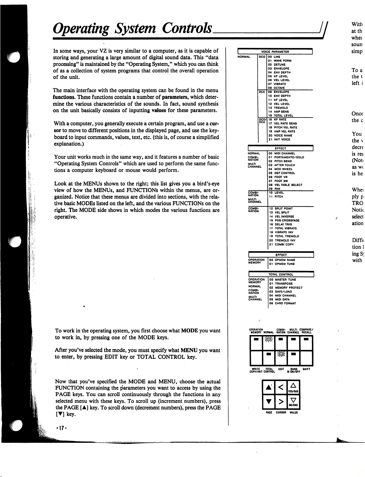
Look
at
the
MENUs
shown
to
the
right;
this
list
gives
you
a
bird's-eye
view
of
how
the
MENUs,
and
FUNCTIONS
within
the
menus,
are
or
ganized.
Notice
that
these
menus
are
divided
into
sections,
with
the
rela
tive
basic
MODEs
listed
on
the
left,
and
the
various
FUNCTIONS
on
the
right.
The
MODE
side
shows
in
which
modes
the
various
functions
are
operative.
To
work
in
the
operating
system,
you
first
choose
what
MODE
you
want
to
work
in,
by
pressing
one
of
the
MODE
keys.
After
you've
selected
the
mode,
you
must
specify
what
MENU
you
want
to
enter,
by
pressing
EDIT
key
or
TOTAL
CONTROL
key.
Now
that
you've
specified
the
MODE
and
MENU,
choose
the
actual
FUNCTION
containing
the
parameters
you
want
to access
by
using
the
PAGE
keys.
You
can
scroll
continuously
through
the
functions
in
any
selected
menu
with
these
keys.
To
scroll
up
(increment
numbers),
press
the
PAGE
[A]
key.
To
scroll
down
(decrement
numbers),
press
the
PAGE
[▼]
key.
EFFECT
NORMAL
COMBI-.
NATION
MULTI
CHANNEL
00
MIDI
CHANNEL
01
PORTAMENTO/
SOLO
02
PITCH
BEND
03
AFTER
TOUCH
04
MOD
WHEEL
05
DEF
CONTROL
06
FOOT
VR
07
FOOTSW
08
VEL
TABLE
SELECT
09
PAN
10
LEVEL
11
PITCH
12
SPLIT
POINT
13
VELSPUT
14
VELINVERSE
15
POSCROSSFADE
16
DELAY
TRIG
17
TOTAL
VIBRATO
18
VIBRATO
INV
19
TOTAL
TREMOLO
20
TREMOLO
INV
21
COMBI
COPY
OPERATION
MEMORY
00
OPMEM
NAME
01
OPMEM
TUNE
With
atth
whei
soun
simp
To
a
the
(
left
i
Once
the
c
You
the
v
decre
is
ret
(Note
as
wt
is
he
Whei
ply
p
TRO
Notic
select
ation
Diffn
tion
1
ingS}
with
OPERATION
COMBI-
MULTI
COMPARE/
MEMORY
NORMAL
NATION
CHANNEL
RECALL
WRITE
TOTAL
EOIT
BANK
SHIFT
COPY/INIT
CONTROL
M
ON/OFF
PAGE
CURSOR
VALUE
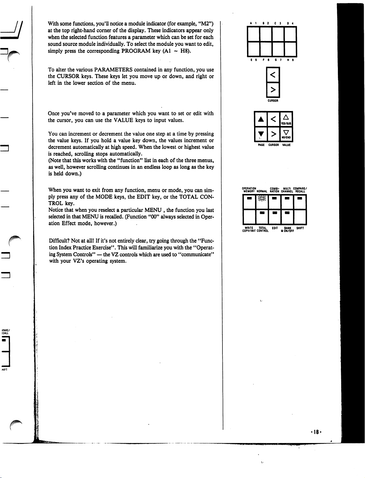
With
some
functions,
you'll
notice
a
module
indicator
(for
example,
"M2")
at
the
top
right-hand
corner
of
the
display.
These
indicators
appear
only
when
the
selected
function
features
a
parameter
which
can
be
set
for
each
sound
source
module
individually.
To
select
the
module
you
want
to
edit,
simply
press
the
corresponding
PROGRAM
key
(Al
-
H8).
To
alter
the
various
PARAMETERS
contained
in
any
function,
you
use
the
CURSOR
keys.
These
keys
let
you
move
up
or
down,
and
right
or
left
in
the
lower
section
of
the
menu.
Once
you've
moved
to
a
parameter
which
you
want
to
set
or
edit
with
the
cursor,
you
can
use
the
VALUE
keys
to
input
values.
You
can
increment
or
decrement
the
value
one
step
at
a
time
by
pressing
the
value
keys.
If
you
hold
a
value
key
down,
the
values
increment
or
decrement
automatically
at
high
speed.
When
the
lowest or
highest
value
is
reached,
scrolling
stops
automatically.
(Note
that
this
works
with
the
"function"
list
in
each
of
the
three
menus,
as
well,
however
scrolling
continues
in
an
endless
loop
as
long
as
the
key
is
held
down.)
When
you
want
to
exit
from
any
function,
menu
or
mode,
you
can sim
ply
press
any
of
the
MODE
keys,
the
EDIT
key,
or
the
TOTAL
CON
TROL
key.
Notice
that
when
you
reselect
a
particular
MENU
,
the
function
you
last
selected
in
that
MENU
is
recalled.
(Function
"00"
always
selected
in
Oper
ation
Effect
mode,
however.)
Difficult?
Not
at
all!
If
it's
not
entirely
clear,
try
going
through
the
"Func
tion
Index
Practice
Exercise".
This
will
familiarize
you
with
the
"Operat
ing
System
Controls"
—
the
VZ
controls
which
are
used
to
"communicate"
with
your
VZ's
operating
system.
CURSOR
PAGE
CURSOR
VALUE
WRITE
TOTAL
EOIT
BANK
SHIFT
COPY/INIT
CONTROL
M
ON/OFF
•18'
Menus
and
Functions
jj
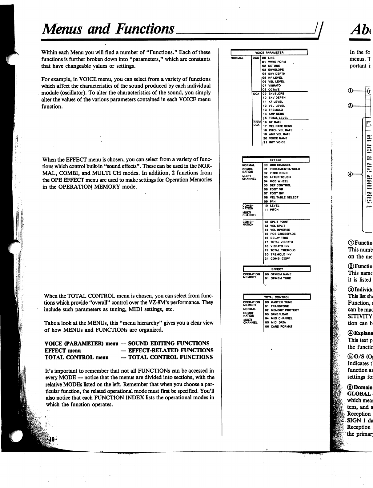
Within
each
Menu
you
will
find
a
number
of
"Functions."
Each
of
these
functions
is
further
broken
down
into
"parameters,"
which
are
constants
that
have
changeable
values
or
settings.
For
example,
in
VOICE
menu,
you
can
select
from
a
variety
of
functions
which
affect
the
characteristics
of
the
sound
produced
by
each
individual
module
(oscillator).
To
alter
the
characteristics
of
the
sound,
you
simply
alter
the
values
of
the
various
parameters
contained
in
each
VOICE
menu
function.
When
the
EFFECT
menu
is
chosen,
you
can
select
from
a
variety
of
func
tions
which
control
built-in
"sound
effects".
These
can
be
used
in
the
NOR
MAL,
COMBI,
and
MULTI
CH
modes.
In
addition,
2
functions
from
the
OPE
EFFECT
menu
are
used
to
make
settings
for
Operation
Memories
in
the
OPERATION
MEMORY
mode.
When
the
TOTAL
CONTROL
menu
is
chosen,
you
can
select
from
func
tions
which
provide
"overall"
control
over
the
VZ-8M's
performance.
They
*
include
such
parameters
as
tuning,
MIDI
settings,
etc.
Take
a
look
at
the
MENUs,
this
"menu
hierarchy"
gives
you
a
clear
view
of
how
MENUs
and
FUNCTIONS
are
organized.
VOICE
(PARAMETER)
menu
—
SOUND
EDITING
FUNCTIONS
EFFECT
menu
—
EFFECT-RELATED
FUNCTIONS
TOTAL
CONTROL
menu
—
TOTAL
CONTROL
FUNCTIONS
It's
important
to
remember
that
not
all
FUNCTIONS
can
be
accessed
in
every
MODE
—
notice
that
the
menus
are
divided
into
sections,
with
the
relative
MODEs
listed
on
the
left.
Remember
that
when
you
choose
a
par
ticular
function,
the
related
operational
mode
must
first
be
specified.
You'll
also
notice
that
each
FUNCTION
INDEX
lists
the
operational
modes
in
which
the
function
operates.
VOICE
PARAMETER
LINE
WAVE
FORM
DETUNE
ENVELOPE
ENV
DEPTH
KF
LEVEL
VEL
LEVEL
VIBRATO
OCTAVE
ENVELOPE
ENV
DEPTH
KF
LEVEL
VEL
LEVEL
TREMOLO
AMP
SENS
TOTAL
LEVEL
KF
RATE
VEL
RATE
SENS
PITCH
VEL
RATE
AMP
VEL
RATE
VOICE
NAME
INIT
VOICE
OPERATION
MEMORY
00
OPMEM
NAME
01
OPMEM
TUNE
TOTAL
CONTROL
COMBI
NATION
MULTI
CHANNEL
00
MASTER
TUNE
01
TRAN8POSE
02
MEMORY
PROTECT
03
SAVE/LOAD
04
MIDI
CHANNEL
05
MIDI
DATA
06
CARD
FORMAT
®—
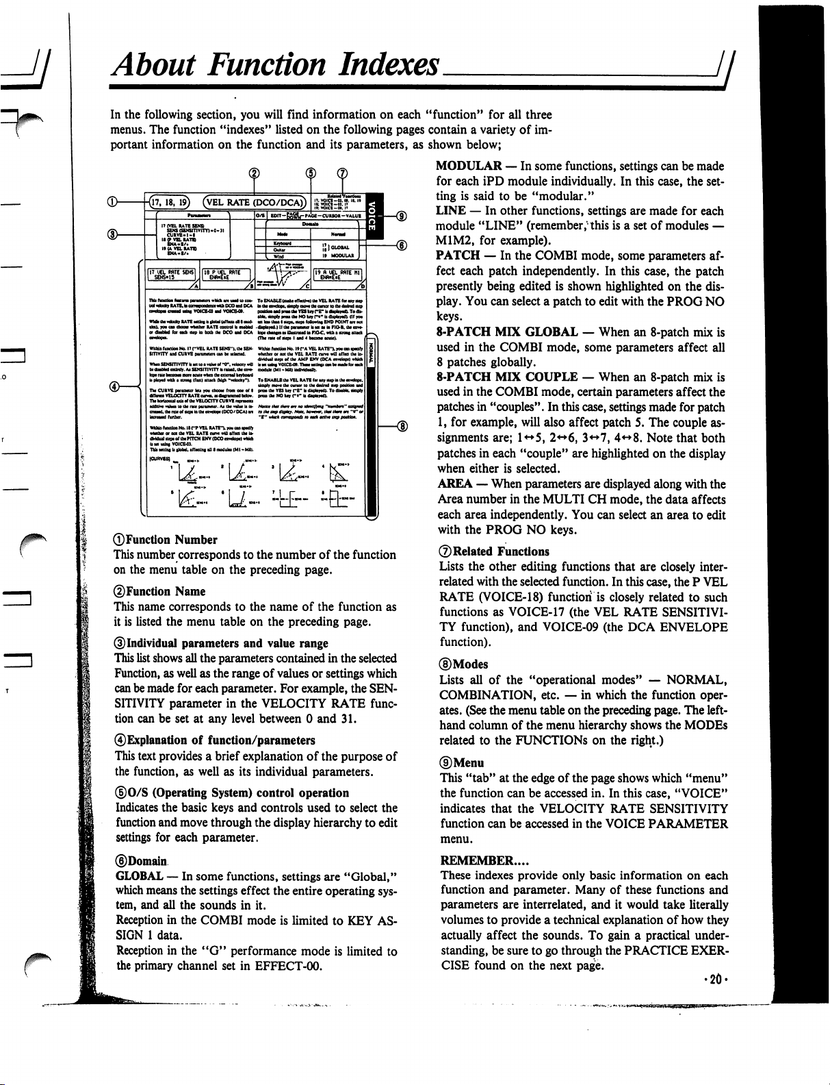
About
Function
Indexes
ji
^
r
VEL
RATE
(DCO/DCA)
To
ENABLE
(nafct
cflttM
da
VEL
RATB
to
toy
lhiwfcidQr
RATE
Mains
b
(total
(rftaid
I
cart-
RATE
to
tadiacp
is
both
cat
000
tad
OCA
No.
IT
("VEL
RATi
SENS"),
tht
SEN-
SmviTY
and
CUKVE
Within
runoim
No.
It
r"A
VBL
RATE"),
you
on
ipajfy
whether
or
not
tht
VBL
RATB
cum
wtt
affM
tht
In-
dMdual
itepi
of
tht
AMP
BNV
{OCA
b
M
ulna
VOICB4*.
ThaM
atunp
can
bt
aiadt
for
atca
nodakt
(Ml-Mt>
iadMdMlh.
Whtn
SENSITIVITY
It
MiWiwtoa
At
SENSHTVITYb
railed,
tat
fa*-
To
BNASLB
tht
VBL
RATB
(ot
any
tup
la
tat
amlopt.
ttapty
mo*t
Iht
cunor
to
tat
dnlnd
iup
potkloa
aad
prat
tht
VES
kty
(~B"
b
dbplaytd).
To
dbaMt,
dnpty
prat
tat
NO
kay
r**
b
tfbpkyai).
Tte
CURVE
paTKMUt
Ira
you
ctoow
from
eat
of
I
«r«r«»
VELOCITY
RATE
cwxn»«^riow>«lbcto».
TW
bortoatal
sdi
*f
tht
VELOCITV
COR
VE
npratan
nha
to
tat
ratt
tht
rax
of
ttptta
tat
cawtoot
(DCO/DCA)
in
»tkt
mp
dt&tr.Nou.
Aoavw.
(Am
Umt
m
Whta
fuocttoo
No.
II
f"P
VEL
RATE"),
you
on
wbttho
or
ooi
tht
VEL
RATB
nm
wU
iffM
tht
b»
dMdttl
wpt
of
tht
PITCH
BNV
(DCO
cowtopt)
wtkh
b
M
mint
VOICED.
TkU
Kttlni
b
itoUI.
tfftctini
iU
I nodufct
(MI
•
Mil.
In
the
following
section,
you
will
find
information
on
each "function"
for
all
three
menus.
The
function
"indexes"
listed
on
the
following
pages
contain
a
variety
of
im
portant
information
on
the
function
and
its
parameters,
as
shown
below;
MODULAR
—
In
some
functions,
settings
can
be
made
for
each
iPD
module
individually.
In
this
case,
the
set
ting
is
said
to
be
"modular."
LINE
—
In
other
functions,
settings
are
made
for
each
module
"LINE"
(remember,"
this
is
a
set
of
modules
—
M1M2,
for
example).
PATCH
—
In
the
COMBI
mode,
some
parameters
af
fect
each
patch
independently.
In
this
case,
the
patch
presently
being
edited
is
shown
highlighted
on
the
dis
play.
You
can
select
a
patch
to
edit
with
the
PROG
NO
keys.
8-PATCH
MIX
GLOBAL
—
When
an
8-patch
mix
is
used
in
the
COMBI
mode,
some
parameters
affect
all
8
patches
globally.
8-PATCH
MIX
COUPLE
—
When
an
8-patch
mix
is
used
in
the
COMBI
mode,
certain
parameters
affect
the
patches
in
"couples". In
this
case,
settings
made
for
patch
1,
for
example,
will
also
affect
patch
5.
The
couple
as
signments
are;
1<*5,
2<-*6,
3<->7,
4<->8.
Note
that
both
patches
in
each
"couple"
are
highlighted
on
the
display
when
either
is
selected.
AREA
—
When
parameters
are
displayed
along
with
the
Area
number
in
the
MULTI
CH
mode,
the
data
affects
each
area
independently.
You
can
select
an
area
to
edit
with
the
PROG
NO
keys.
©Related
Functions
Lists
the
other
editing
functions
that
are
closely
inter
related
with
the
selected
function.
In
this
case,
the
P
VEL
RATE
(VOICE-18)
function
is
closely
related
to
such
functions
as
VOICE-17
(the
VEL
RATE
SENSITIVI
TY
function),
and
VOICE-09
(the
DCA
ENVELOPE
function).
©Modes
Lists
all
of
the
"operational
modes"
—
NORMAL,
COMBINATION,
etc.
—
in
which
the
function
oper
ates.
(See
the
menu
table
on
the
preceding
page.
The
left-
hand
column
of
the
menu
hierarchy
shows
the
MODEs
related
to
the
FUNCTIONS
on
the
right.)
©Menu
This
"tab"
at
the
edge
of
the
page
shows
which
"menu"
the
function
can
be
accessed
in.
In
this
case,
"VOICE"
indicates
that
the
VELOCITY
RATE
SENSITIVITY
function
can
be
accessed
in
the
VOICE
PARAMETER
menu.
REMEMBER....
These
indexes
provide
only
basic
information
on
each
function
and
parameter.
Many
of
these
functions
and
parameters
are
interrelated,
and
it
would
take
literally
volumes
to
provide
a
technical
explanation
of
how
they
actually
affect
the
sounds.
To
gain
a
practical
under
standing,
be
sure
to
go
through
the
PRACTICE
EXER
CISE
found
on
the
next
page.
•20-
©Function
Number
This
number
corresponds
to
the
number
of
the
function
on
the
menu
table
on
the
preceding
page.
©Function
Name
This
name
corresponds
to
the
name
of
the
function
as
it
is
listed
the
menu
table
on
the
preceding
page.
©Individual
parameters
and
value
range
This
list
shows
all
the
parameters
contained
in
the
selected
Function,
as well
as the
range
of
values
or
settings
which
can
be
made
for
each
parameter.
For
example,
the
SEN
SITIVITY
parameter
in
the
VELOCITY
RATE
func
tion
can
be
set
at
any
level
between
0
and
31.
©Explanation
of
function/parameters
This
text
provides
a
brief
explanation
of
the
purpose
of
the
function,
as
well
as
its
individual
parameters.
©0/S
(Operating
System)
control
operation
Indicates
the
basic
keys
and
controls
used
to
select
the
function
and
move
through
the
display
hierarchy
to
edit
settings
for
each
parameter.
©Domain
GLOBAL
—
In
some
functions,
settings
are
"Global,"
which
means
the
settings
effect
the
entire
operating
sys
tem,
and
all
the
sounds
in
it.
Reception
in
the
COMBI
mode
is
limited
to
KEY
AS
SIGN
1
data.
Reception
in
the
"G"
performance
mode
is
limited
to
the
primary
channel
set
in
EFFECT-00.
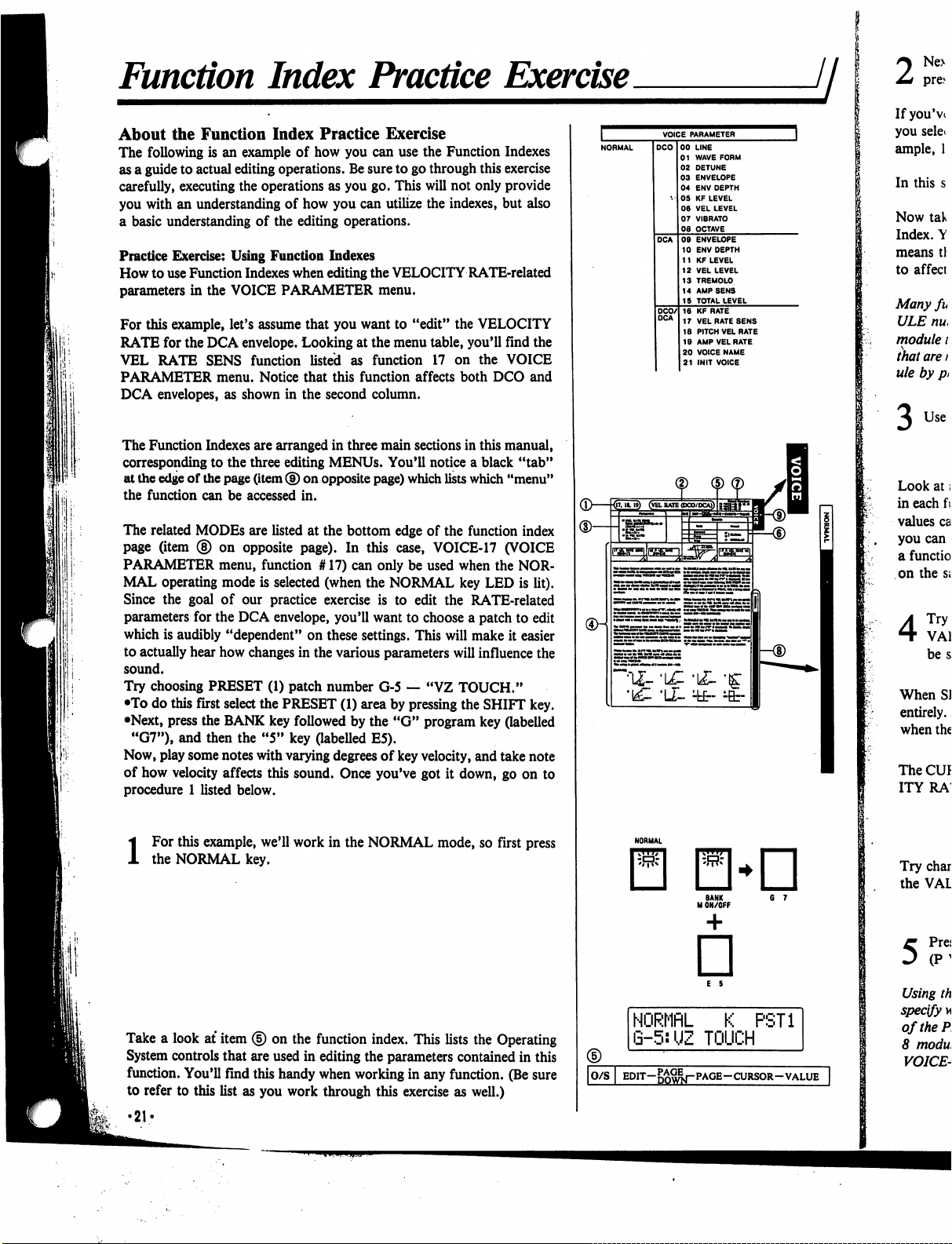
Function
Index
Practice
Exercise
About
the
Function
Index
Practice
Exercise
The
following
is
an
example
of
how
you
can
use
the
Function
Indexes
as
a
guide
to
actual
editing
operations.
Be
sure
to
go
through
this
exercise
carefully,
executing
the
operations
as
you
go.
This
will
not only
provide
you
with
an
understanding
of
how
you
can
utilize
the
indexes,
but
also
a
basic
understanding
of
the
editing
operations.
Practice
Exercise:
Using
Function
Indexes
How
to
use
Function
Indexes
when
editing
the
VELOCITY
RATE-related
parameters
in
the
VOICE
PARAMETER
menu.
For
this
example,
let's
assume
that
you
want
to
"edit"
the
VELOCITY
RATE
for
the
DCA
envelope.
Looking
at
the
menu
table,
you'll
find
the
VEL
RATE
SENS
function
listed
as
function
17
on
the
VOICE
PARAMETER
menu.
Notice
that
this
function
affects
both
DCO
and
DCA
envelopes,
as
shown
in
the
second
column.
The
Function
Indexes
are
arranged
in
three
main
sections
in
this
manual,
corresponding
to
the
three
editing
MENUs.
You'll
notice
a
black
"tab"
at
the
edge
of
the
page
(item
®
on
opposite
page)
which
lists
which
"menu"
the
function
can
be
accessed
in.
The
related
MODEs
are
listed
at
the
bottom
edge of
the
function
index
page
(item
®
on
opposite
page).
In
this
case,
VOICE-17
(VOICE
PARAMETER
menu,
function
#
17)
can
only
be
used
when
the
NOR
MAL
operating
mode
is
selected
(when
the
NORMAL
key
LED
is
lit).
Since
the
goal
of
our
practice
exercise
is
to
edit
the
RATE-related
parameters
for
the
DCA
envelope,
you'll
want
to
choose
a
patch
to
edit
which
is
audibly
"dependent"
on
these
settings.
This
will
make
it
easier
to
actually
hear
how
changes
in
the
various
parameters
will
influence the
sound.
Try
choosing
PRESET
(1)
patch
number
G-5
—
"VZ
TOUCH."
•To
do
this
first
select
the
PRESET
(1)
area
by
pressing
the
SHIFT
key.
•Next,
press
the
BANK
key
followed
by
the
"G"
program
key
(labelled
"G7"),
and
then
the
"5"
key
(labelled
E5).
Now,
play
some
notes
with
varying
degrees
of
key
velocity,
and
take
note
of
how
velocity
affects
this
sound.
Once
you've
got
it
down,
go
on
to
procedure
1
listed
below.
i
For
this
example,
we'll
work
in
the
NORMAL
mode,
so
first
press
the
NORMAL
key.
Take
a
look
at
item
<§)
on
the
function
index.
This
lists
the
Operating
System
controls
that
are
used
in
editing
the
parameters
contained
in
this
function.
You'll
find
this
handy
when
working
in
any
function.
(Be
sure
to
refer
to
this
list
as
you
work
through
this
exercise
as
well.)
•21?
(D—kr
NORMflL
K
PST1
G-5:UZ
TOUCH
|O/S
I
EDIT-g^j-PAGE-CURSOR-VALUE
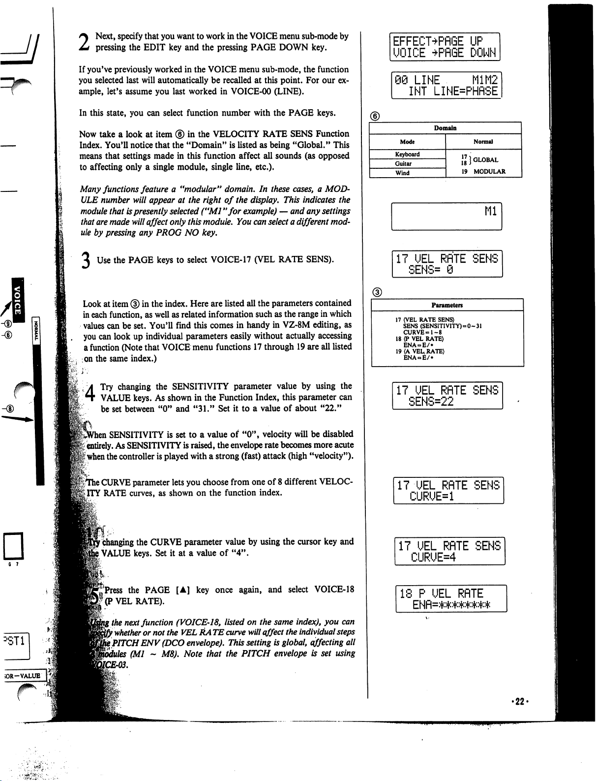
6 7
2
Next,
specify
that
you
want
to
work
in
the
VOICE
menu
sub-mode
by
pressing
the
EDIT
key
and
the
pressing
PAGE
DOWN
key.
If
you've
previously
worked
in
the
VOICE
menu
sub-mode,
the
function
you
selected
last
will
automatically
be
recalled
at
this
point.
For
our
ex
ample,
let's
assume
you
last
worked
in
VOICE-00
(LINE).
In
this
state,
you
can
select
function
number
with
the
PAGE
keys.
Now
take
a
look
at
item
®
in
the
VELOCITY
RATE
SENS
Function
Index.
You'll
notice
that
the
"Domain"
is
listed
as
being
"Global."
This
means
that
settings
made
in
this
function
affect
all
sounds
(as
opposed
to
affecting
only
a
single
module,
single
line,
etc.).
Many
functions
feature
a
"modular"
domain.
In
these
cases,
a
MOD
ULE
number
will
appear
at
the
right
of
the
display.
This
indicates
the
module
that
is
presently
selected
("Ml
"for
example)
—
and
any
settings
that
are
made
will
affect
only
this
module.
You
can
select
a
different
mod
ule
by
pressing
any
PROG
NO
key.
Use
the
PAGE
keys
to
select
VOICE-17
(VEL
RATE
SENS).
Look
at
item
®
in
the
index.
Here
are
listed
all
the
parameters
contained
in
each
function,
as
well
as
related
information
such
as
the
range
in
which
values
can
be
set.
You'll
find
this
comes
in
handy
in
VZ-8M
editing,
as
you
can
look
up
individual
parameters
easily
without
actually
accessing
a
function
(Note
that
VOICE
menu
functions
17
through
19
are
all
listed
on
the
same
index.)
4
Try
changing
the
SENSITIVITY
parameter
value
by
using
the
VALUE
keys.
As
shown
in
the
Function
Index,
this
parameter
can
be
set
between
"0" and
"31."
Set
it
to
a
value
of
about
"22."
,
SENSITIVITY
is
set
to
a
value
of
"0",
velocity
will
be
disabled
'i
entirely.
As
SENSITIVITY
is
raised,
the
envelope
rate
becomes
more
acute
|
when
the
controller
is
played
with
a
strong
(fast)
attack
(high
"velocity").
|TThe
CURVE
parameter
lets
you
choose
from
one
of
8
different
VELOC
ITY
RATE
curves,
as
shown
on
the
function
index.
r
changing
the
CURVE
parameter
value
by
using
the
cursor
key
and
)
VALUE
keys.
Set
it
at
a
value
of
"4".
ft..
j'Press
the
PAGE
[A]
key
once
again,
and
select
VOICE-18
'(P
VEL
RATE).
\
the
next
function
(VOICE-18,
listed
on
the
same
index),
you
can
}
whether
or
not
the
VEL
RA
TE
curve
will
affect
the
individual
steps
t
PITCH
ENV
(DCO
envelope).
This
setting
is
global,
affecting
all
(Ml
~
M8).
Note
that
the
PITCH
envelope
is
set
using
EFFECT+PflGE
UP
UOICE
+PRGE
DOWN
98
LINE
M1M2
INT
LINE=PHflSE
Domain
Mode
Keyboard
Guitar
Wind
Normal
\l}
GLOBAL
19
MODULAR
Ml
17
UEL
RflTE
SENS
SENS=
0
Parameters
17
(VEL
RATE
SENS)
SENS
(SENSITIVITY)=0-31
CURVE=1-8
18
(P
VEL
RATE)
ENA
= E/»
19
(A
VEL.
RATE)
ENA
E/
IT
UEL
RflTE
SENS
SENS=22
IT
UEL
RflTE
SENS
CURUE=1
IT
UEL
RflTE
SENS
CURUE=4
18
P
UEL
RflTE
ENfl=*****##*
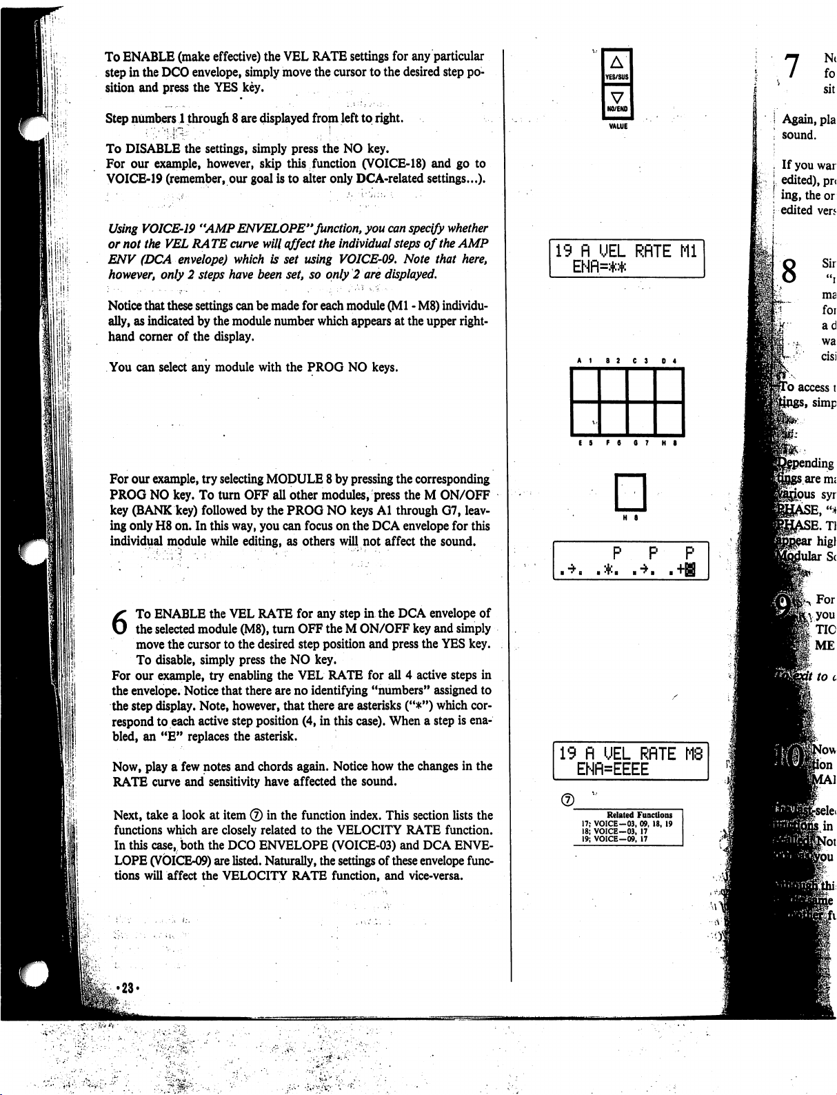
1;!'
1
i
.
I
To
ENABLE
(make
effective)
the
VEL
RATE
settings
for
any
particular
step
in
the
DCO
envelope,
simply
move
the
cursor
to
the
desired
step
po
sition
and
press
the
YES
key.
Step
numbers
1
through
8
are
displayed
from
left
to
right.
To
DISABLE
the
settings,
simply
press
the
NO
key.
For
our
example,
however,
skip
this
function
(VOICE-18)
and
go
to
VOICE-19
(remember,
our
goal
is
to
alter
only
DCA-related
settings...).
Using
VOICE-19
"AMP
ENVELOPE"
function,
you
can
specify
whether
or
not
the
VEL
RA
TE
curve
will
affect
the
individual
steps
of
the
AMP
ENV
(DCA
envelope)
which
is
set
using
VOICE-09.
Note
that
here,
however,
only
2
steps
have
been
set,
so
only
2
are
displayed.
Notice
that
these
settings
can
be
made
for
each
module
(Ml
-
M8)
individu
ally,
as
indicated
by
the
module
number
which
appears
at
the
upper
right-
hand
corner
of
the
display.
You
can
select
any
module
with
the
PROG
NO
keys.
For
our
example,
try
selecting
MODULE
8
by
pressing
the
corresponding
PROG
NO
key.
To
turn
OFF
all
other
modules,
press
the
M
ON/OFF
key
(BANK
key)
followed
by
the
PROG
NO
keys
Al
through
G7,
leav
ing
only
H8
on.
In
this
way,
you
can
focus
on
the
DCA
envelope
for
this
individual
module
while
editing,
as
others
will
not
affect
the
sound.
6
To
ENABLE
the
VEL
RATE
for
any
step in
the
DCA
envelope
of
the
selected
module
(M8),
turn
OFF
the
M
ON/OFF
key
and
simply
move
the cursor
to
the
desired
step
position
and
press
the
YES
key.
To
disable,
simply
press
the
NO
key.
For
our
example,
try
enabling
the
VEL
RATE
for
all
4
active
steps
in
the
envelope.
Notice
that
there
are
no
identifying
"numbers"
assigned
to
the
step
display.
Note,
however,
that
there
are
asterisks
("#")
which
cor
respond
to
each
active
step
position
(4,
in
this
case).
When
a
step
is
ena
bled,
an
"E"
replaces
the
asterisk.
Now,
play
a
few
notes
and
chords
again.
Notice
how
the
changes
in
the
RATE
curve
and
sensitivity
have
affected
the
sound.
Next,
take
a
look
at
item
®
in
the
function
index.
This
section
lists
the
functions
which
are
closely
related
to
the
VELOCITY
RATE
function.
In
this
case,
both
the
DCO
ENVELOPE
(VOICE-03)
and
DCA
ENVE
LOPE
(VOICE-09)
are
listed.
Naturally,
the
settings
of
these
envelope
func
tions
will
affect
the
VELOCITY
RATE
function,
and
vice-versa.
•23*
A
YES/SUS
V
NO/ENO
19
fl
UEL
RflTE
Ml
ENfl=:+:*
E
5
F
8
6
7
H
8
□
H
S
P
P P
19
fl
UEL
RflTE
ENFNEEEE
Related
Functions
17;
VOICE-03,
09.
18,
19
18;
VOICE-03,
17
19;
VOICE-09,
17
8
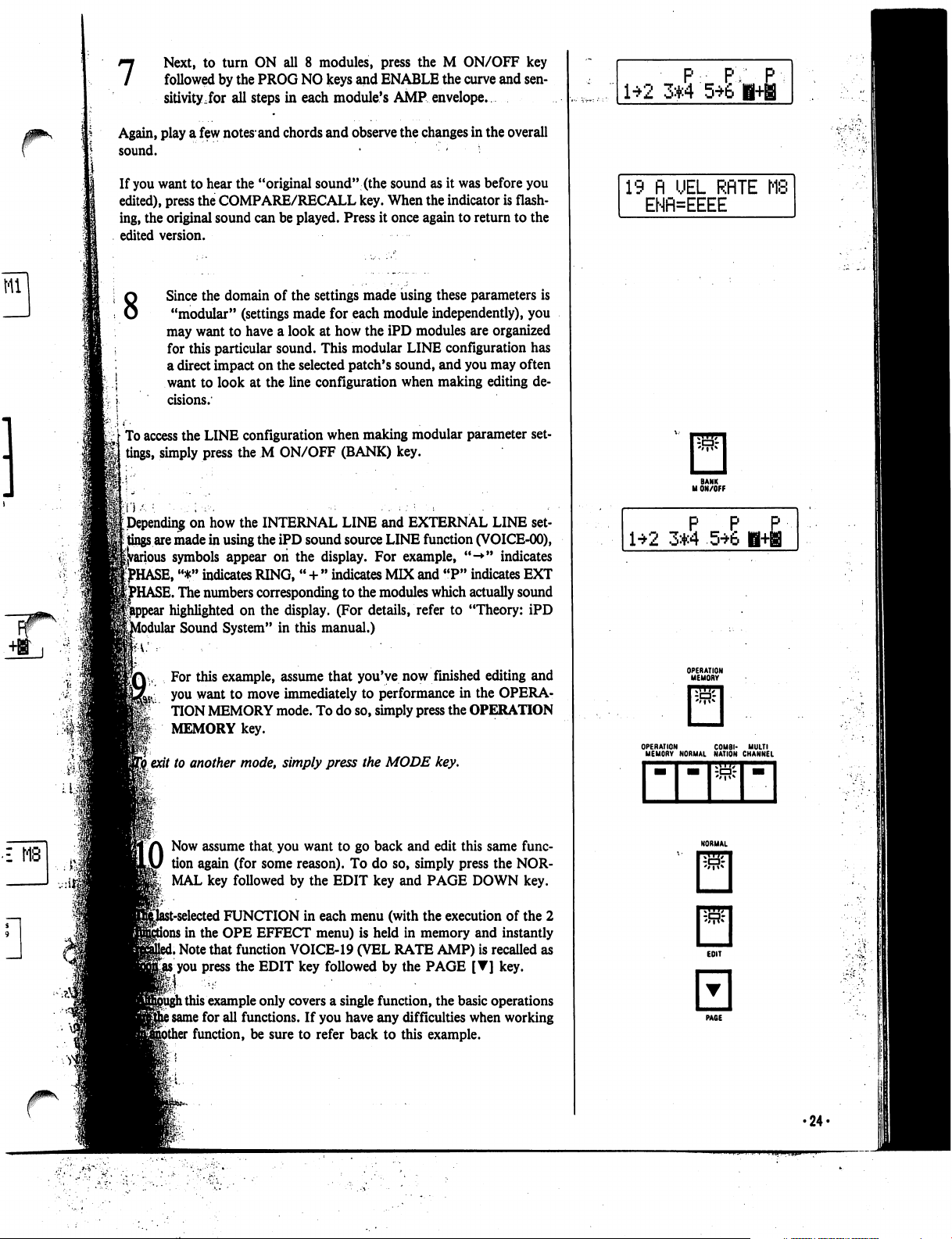
7
Next,
to
turn
ON
all
8
modules,
press
the
M
ON/OFF
key
followed
by
the
PROG
NO
keys
and
ENABLE
the
curve
and
sen
sitivity,for
all
steps
in
each
module's
AMP
envelope.
Again,
play
a
few
notes*
and
chords
and
observe
the
changes
in
the
overall
sound.
• -
•
If
you
want
to
hear
the
"original
sound"
(the
sound
as
it
was
before
you
edited),
press
the
COMPARE/RECALL
key.
When
the
indicator
is
flash
ing,
the
original
sound
can
be
played.
Press
it
once
again
to
return to the
edited
version.
8
£
MB
Since
the
domain
of
the
settings
made
using
these
parameters
is
"modular"
(settings
made
for
each
module
independently),
you
may
want
to
have
a
look
at
how
the
iPD
modules
are
organized
for
this
particular
sound.
This
modular
LINE
configuration
has
a
direct
impact
on
the
selected
patch's
sound,
and
you
may
often
want
to
look
at
the
line
configuration
when
making
editing
de
cisions.
To
access
the
LINE
configuration
when
making
modular
parameter
set
tings,
simply
press
the
M
ON/OFF
(BANK)
key.
Depending
on
how
the
INTERNAL
LINE
and
EXTERNAL
LINE
set
tings
are
made
in
using
the
iPD
sound
source
LINE
function
(VOICE-00),
►us
symbols
appear
on
the
display.
For
example,
"-*"
indicates
^HASE,
"*"
indicates
RING,
"
+
"
indicates
MIX
and
"P"
indicates
EXT
HASE.
The
numbers
corresponding
to
the
modules
which
actually
sound
highlighted
on
the
display.
(For
details,
refer
to
"Theory:
iPD
Modular
Sound
System"
in
this
manual.)
For
this
example,
assume
that
you've
now
finished
editing
and
you
want
to
move
immediately
to
performance
in
the
OPERA-
TION
MEMORY
mode.
To
do
so,
simply
press
the
OPERATION
MEMORY
key.
I
exit
to
another
mode,
simply
press
the
MODE
key.
LO
Now
assume
that,
you
want
to
go back
and
edit
this
same
func
tion
again
(for
some
reason).
To
do
so,
simply
press
the
NOR
MAL
key
followed
by
the
EDIT
key
and
PAGE
DOWN
key.
it-selected
FUNCTION
in
each
menu
(with
the
execution
of
the
2
i
in
the
OPE
EFFECT
menu)
is
held
in
memory
and
instantly
i
Note
that
function
VOICE-19
(VEL
RATE
AMP)
is
recalled
as
gjts
you
press
the
EDIT
key
followed
by
the
PAGE
[T]
key.
l
this
example
only
covers
a
single
function,
the
basic
operations
i
same
for
all
functions.
If
you
have
any
difficulties
when
working
function,
be
sure
to
refer
back
to
this
example.
P
PY
1*2
3*4
56'
19 n
UEL
RRTE
MS
ENfl=EEEE
P P
£
1*2
3*4
5*6
H+B
OPERATION
COMBI-
MULTI
MEMORY
NORMAL
NATION
CHANNEL
•24-
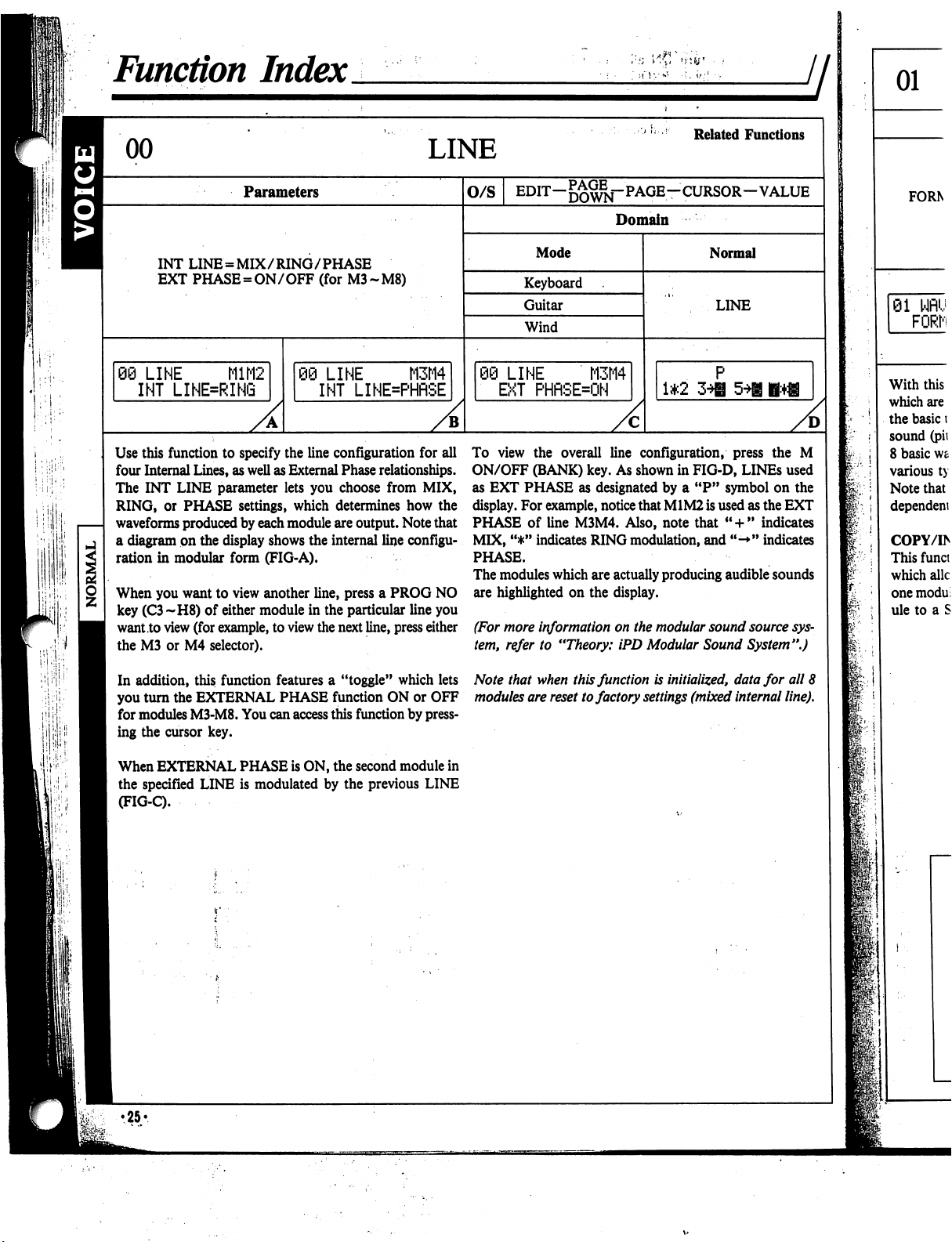
h
•:
■'.
i
,;
Function
Index
LINE
Related
Functions
Parameters
INT
LINE
=
MIX/RING/PHASE
EXT
PHASE
=
ON/OFF
(for
M3-M8)
06
LINE
M1M2
INT
LINE=RING
)
LINE
M3M4
INT
LINE=PHflSE
O/S
EDIT-^^-PAGE-CURSOR-VALUE
Domain
Mode
Keyboard
Guitar
Wind
:i
LINE
M3M4
EXT
PHRSEON
Normal
LINE
1*2
A
Use
this
function
to
specify
the
line
configuration
for
all
four
Internal
Lines,
as
well
as
External
Phase
relationships.
The
INT
LINE
parameter
lets
you
choose
from
MIX,
RING,
or
PHASE
settings,
which
determines
how
the
waveforms
produced
by
each
module
are
output.
Note
that
a
diagram
on
the
display
shows
the
internal
line
configu
ration
in
modular
form
(FIG-A).
When
you
want
to
view
another
line,
press
a
PROG
NO
key
(C3~H8)
of
either
module
in
the
particular
line
you
want
to
view
(for
example,
to
view
the
next
line,
press
either
the
M3
or
M4
selector).
In
addition,
this
function
features
a
"toggle"
which
lets
you
turn
the
EXTERNAL
PHASE
function
ON
or
OFF
for
modules
M3-M8.
You
can
access
this
function
by
press
ing
the
cursor
key.
When
EXTERNAL
PHASE
is
ON,
the
second
module
in
the
specified
LINE
is
modulated
by
the
previous
LINE
(FIG-C).
To
view
the
overall
line
configuration,
press
the
M
ON/OFF
(BANK)
key.
As
shown
in
FIG-D,
LINEs
used
as
EXT
PHASE
as
designated
by
a
"P"
symbol
on
the
display.
For
example,
notice
that
M1M2
is
used
as
the
EXT
PHASE
of
line
M3M4.
Also,
note
that
"
+
"
indicates
MIX,
"*"
indicates
RING
modulation,
and
"->"
indicates
PHASE.
The
modules
which
are
actually
producing
audible
sounds
are
highlighted
on
the
display.
(For
more
information
on
the
modular
sound
source
sys
tem,
refer
to
"Theory:
iPD
Modular
Sound
System".)
Note
that
when
this
function
is
initialized,
data
for
all
8
modules
are
reset
to
factory
settings
(mixed
internal
line).
f:
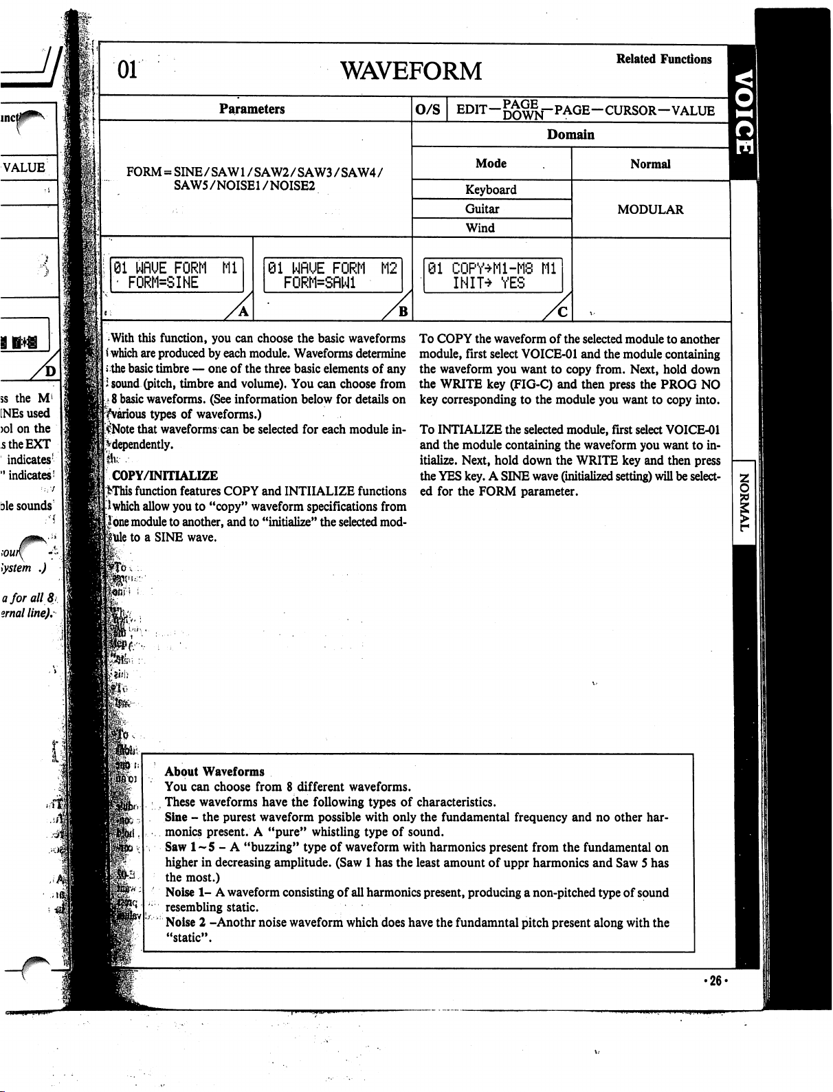
01
WAVEFORM
Related
Functions
Parameters
O/S
EDIT-^^j-PAGE-CURSOR-VALUE
^
Domain
FORM
=
SINE/SAW1
/SAW2/SAW3/SAW4/
SAW5/NOISE1
/NOISE2
Mode
Keyboard
Guitar
Wind
01
WflUE
FORM
Ml
'
FORM=SINE
81
NflUE
FORM
M2
FORM=SflNl
01
CQPY+M-M8
Ml
INIT^
YES
Normal
MODULAR
With
this
function,
you
can
choose
the
basic
waveforms
*
which
are
produced
by
each
module.
Waveforms
determine
the
basic
timbre
—
one
of
the
three
basic
elements
of
any
i
sound
(pitch,
timbre
and
volume).
You
can
choose
from
8
basic
waveforms.
(See
information
below
for
details
on
^various
types
of
waveforms.)
$Note
that
waveforms
can
be
selected
for
each
module
in
dependently.
Ik---
COPY/INITIALIZE
>This
function
features
COPY
and
INITIALIZE
functions
I
which
allow
you
to
"copy"
waveform
specifications
from
lone
module
to
another,
and
to
"initialize"
the
selected
mod
ule
to
a
SINE
wave.
To
COPY
the
waveform
of
the
selected
module
to
another
module,
first
select
VOICE-01
and
the
module
containing
the
waveform
you
want
to
copy
from.
Next,
hold
down
the
WRITE
key
(FIG-C)
and
then
press
the
PROG
NO
key
corresponding
to
the
module
you
want
to
copy
into.
To
INTIALIZE
the
selected
module,
first
select
VOICE-01
and
the
module
containing
the
waveform
you
want
to
in
itialize.
Next,
hold
down
the
WRITE
key
and
then
press
the
YES
key.
A
SINE
wave
(initialized
setting)
will
be
select
ed
for
the
FORM
parameter.
ft*
About
Waveforms
You
can
choose
from
8
different
waveforms.
,
These
waveforms
have
the
following
types
of
characteristics.
Sine
-
the
purest
waveform
possible
with
only
the
fundamental
frequency
and
no
other
har
monics
present.
A
"pure"
whistling
type
of
sound.
Saw
1-5
-
A
"buzzing"
type
of
waveform
with
harmonics
present
from
the
fundamental
on
higher
in
decreasing
amplitude.
(Saw
1
has
the
least
amount
of
uppr
harmonics
and
Saw
5
has
the
most.)
Noise
1-
A
waveform
consisting
of
all
harmonics
present,
producing
a
non-pitched
type
of
sound
resembling
static.
Noise
2
-Anothr
noise
waveform
which
does
have
the
fundamntal
pitch
present
along
with
the
"static".
•26*
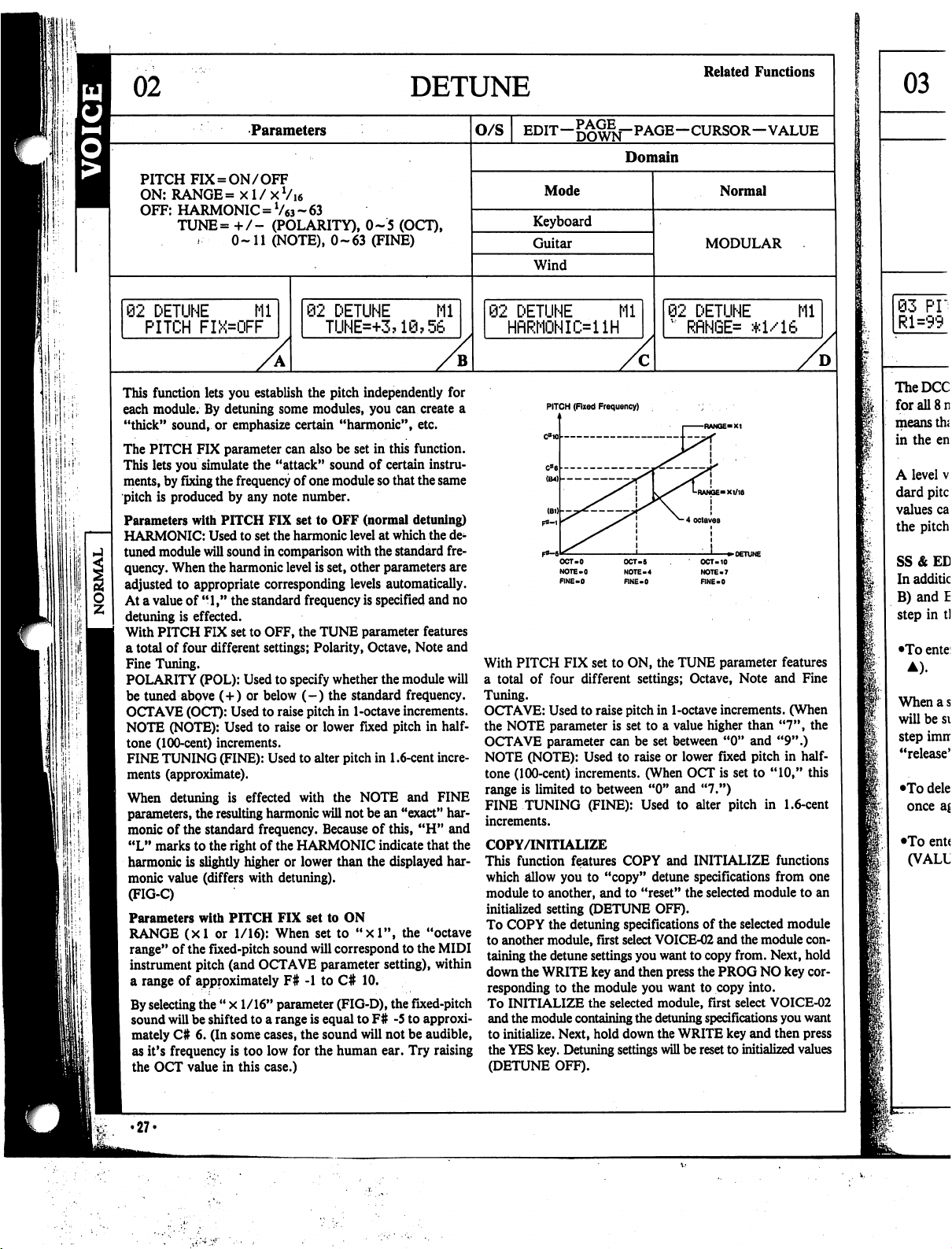
DETUNE
Related
Functions
Parameters
O/S
EDIT—
—CURSOR—VALUE
Domain
PITCH
FIX
=
ON/OFF
ON:
RANGE=
xl/xVi6
OFF:
HARMONIC
=
V63
~
63
TUNE=
+
/-
(POLARITY),
0-5
(OCT),
0-11
(NOTE),
0-63
(FINE)
Mode
Keyboard
Guitar
Wind
Normal
MODULAR
92
DETUNE
Ml
PITCH
FIX=OFF
02
DETUNE
Mi
TUNE=+3?1@?56
2
DETUNE
Mi
HfiRMONIi>ilH
02
DETUNE
Ml
"
RflNGE=
*1/16
B
D
if:.
1
iill:
This
function
lets
you
establish
the
pitch
independently
for
each
module.
By
detuning
some
modules,
you
can
create
a
"thick"
sound,
or
emphasize
certain
"harmonic",
etc.
The
PITCH
FIX
parameter
can
also
be
set
in
this
function.
This
lets
you
simulate
the
"attack"
sound
of
certain
instru
ments,
by
fixing
the
frequency
of
one
module
so
that
the
same
pitch
is
produced
by
any
note
number.
Parameters
with
PITCH
FIX
set
to
OFF
(normal
detuning)
HARMONIC:
Used
to
set
the
harmonic
level
at
which
the
de
tuned
module
will
sound
in
comparison
with
the
standard
fre
quency.
When
the
harmonic
level
is
set,
other
parameters
are
adjusted
to
appropriate
corresponding
levels
automatically.
At
a
value
of
"1,"
the
standard
frequency
is
specified
and
no
detuning
is
effected.
With
PITCH
FIX
set
to
OFF,
the
TUNE
parameter
features
a
total
of
four
different
settings;
Polarity,
Octave,
Note
and
Fine
Tuning.
POLARITY
(POL):
Used
to
specify
whether
the
module
will
be
tuned
above
(+)
or
below
(-)
the
standard
frequency.
OCTAVE
(OCT):
Used
to
raise
pitch
in
1-octave
increments.
NOTE
(NOTE):
Used
to
raise
or
lower
fixed pitch
in
half
tone
(100-cent)
increments.
FINE
TUNING
(FINE):
Used
to
alter
pitch
in
1.6-cent
incre
ments
(approximate).
When
detuning
is
effected
with
the
NOTE
and
FINE
parameters,
the
resulting
harmonic
will
not
be
an
"exact"
har
monic
of
the
standard
frequency.
Because of
this,
"H"
and
"L"
marks
to
the
right
of
the
HARMONIC
indicate that
the
harmonic
is
slightly
higher
or
lower
than
the
displayed
har
monic
value
(differs
with
detuning).
(FIG-C)
Parameters
with
PITCH
FIX
set
to
ON
RANGE
(xl
or
1/16):
When
set
to
"xl",
the
"octave
range"
of
the
fixed-pitch
sound
will
correspond
to
the
MIDI
instrument
pitch
(and
OCTAVE
parameter
setting),
within
a
range
of
approximately
F#
-1
to
C#
10.
By
selecting
the
"
x
1/16"
parameter
(FIG-D),
the
fixed-pitch
sound
will
be
shifted
to
a
range
is
equal
to
F#
-5
to
approxi
mately
C#
6.
(In
some
cases,
the
sound
will
not
be
audible,
as
it's
frequency
is
too
low
for
the
human
ear.
Try
raising
the
OCT
value
in
this
case.)
•27-
PITCH
(Fixed
Frequency)
OCT-5
NOTE-4
RNE-0
OCT-10
NOTE-7
FINE-0
With
PITCH
FIX
set
to
ON,
the
TUNE
parameter
features
a
total
of
four
different
settings;
Octave,
Note
and
Fine
Tuning.
OCTAVE:
Used
to
raise
pitch
in
1-octave
increments.
(When
the
NOTE
parameter
is
set
to
a
value
higher
than
"7",
the
OCTAVE
parameter
can be
set
between
"0"
and
"9".)
NOTE
(NOTE):
Used
to
raise
or
lower
fixed
pitch
in
half
tone
(100-cent)
increments.
(When
OCT
is
set
to
"10,"
this
range
is
limited
to
between
"0"
and
"7.")
FINE
TUNING
(FINE):
Used
to
alter
pitch
in
1.6-cent
increments.
COPY/INITIALIZE
This
function
features
COPY
and
INITIALIZE
functions
which
allow
you
to
"copy"
detune
specifications
from
one
module
to
another,
and
to
"reset"
the
selected
module
to
an
initialized
setting
(DETUNE
OFF).
To
COPY
the
detuning
specifications
of
the
selected
module
to
another
module,
first
select
VOICE-02
and
the
module
con
taining
the
detune
settings
you
want
to
copy
from.
Next,
hold
down
the
WRITE
key
and
then
press
the
PROG
NO
key
cor
responding
to
the
module
you
want
to
copy
into.
To
INITIALIZE
the
selected
module,
first
select
VOICE-02
and
the
module
containing
the
detuning
specifications
you
want
to
initialize.
Next,
hold
down
the
WRITE
key
and
then
press
the
YES
key.
Detuning
settings
will
be
reset
to
initialized
values
(DETUNE
OFF).
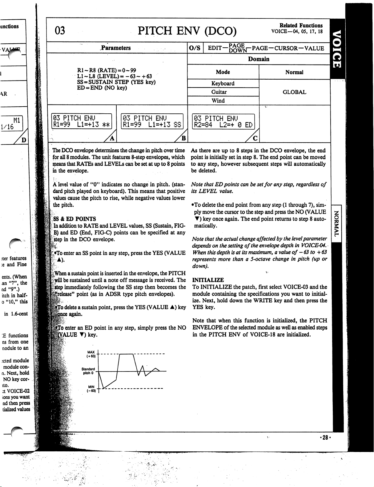
03
PITCH
ENV
(DCO)
Related
Functions
VOICE—04,
05,
17,
18
Parameters
R1-R8
(RATE)
=
0-99
L1-L8
(LEVEL)=
-63-
+63
SS=SUSTAIN
STEP
(YES
key)
ED
=
END(NOkey)
93
PITCH
ENU
Rl=99
Ll=+13
The
DCO
envelope
determines
the
change
in
pitch
over
time
As
there
are
up
to
8
steps
in
the
DCO
envelope,
the
end
for
all
8
modules.
The
unit
features
8-step
envelopes,
which
point
is
initially
set
in
step
8.
The
end
point
can
be
moved
means
that
RATEs
and
LEVELS
can
be
set
at
up
to
8
points
to
any
step,
however
subsequent
steps
will
automatically
in
the
envelope.
be
deleted.
A
level
value
of
"0"
indicates
no
change
in
pitch,
(stan
dard
pitch
played
on
keyboard).
This
means
that
positive
values
cause
the
pitch
to
rise,
while
negative
values
lower
the
pitch.
SS
& ED
POINTS
t
In
addition
to
RATE
and
LEVEL
values,
SS
(Sustain,
FIG-
jB)
and
ED
(End,
FIG-C)
points
can
be
specified
at
any
£step
in
the
DCO
envelope.
•To
enter
an SS
point
in
any
step,
press
the
YES
(VALUE
83
PITCH
ENU
Rl=99
Ll=+13
SS
O/S
EDIT-^^j-PAGE-CURSOR-VALUE
Domain
Mode
Keyboard
Guitar
Wind
S3
PITCH
ENU
R2=84
L2=+
0
EC-
Normal
GLOBAL
||When
a
sustain
point
is
inserted
in
the
envelope,
the
PITCH
Frwill
be
sustained
until
a
note
off
message
is
received.
The
*;
step
immediately
following
the
SS
step
then
becomes
the
e"
point
(as
in
ADSR
type
pitch
envelopes).
'o
delete
a
sustain
point,
press
the
YES
(VALUE
A)
key
Note
that
ED
points
can
be
set
for
any
step,
regardless
of
its
LEVEL
value.
•To
delete
the
end
point
from
any
step
(1
through
7),
sim
ply
move
the
cursor
to
the
step
and
press
the
NO
(VALUE
T)
key
once
again.
The
end
point
returns
to
step
8
auto
matically.
Note
that
the
actual
change
effected
by
the
level
parameter
depends
on
the
setting
of
the
envelope
depth
in
VOICE-04.
When
this
depth
is
at
its
maximum,
a
value
of
-63
to
+
63
represents
more
than
a
5-octave
change
in
pitch
(up
or
down).
INITIALIZE
To
INITIALIZE
the
patch,
first
select
VOICE-03
and
the
module
containing
the
specifications
you
want
to
initial
ize.
Next,
hold
down
the
WRITE
key
and
then
press
the
YES
key.
Note
that
when
this
function
is
initialized,
the
PITCH
To
enter
an
ED
point
in
any
step,
simply
press
the
NO
ENVELOPE
of
the
selected
module
as
well
as
enabled
steps
£ALUE
T)
key.
in
the
PITCH
ENV
of
VOICE-18
are
initialized.
•28-
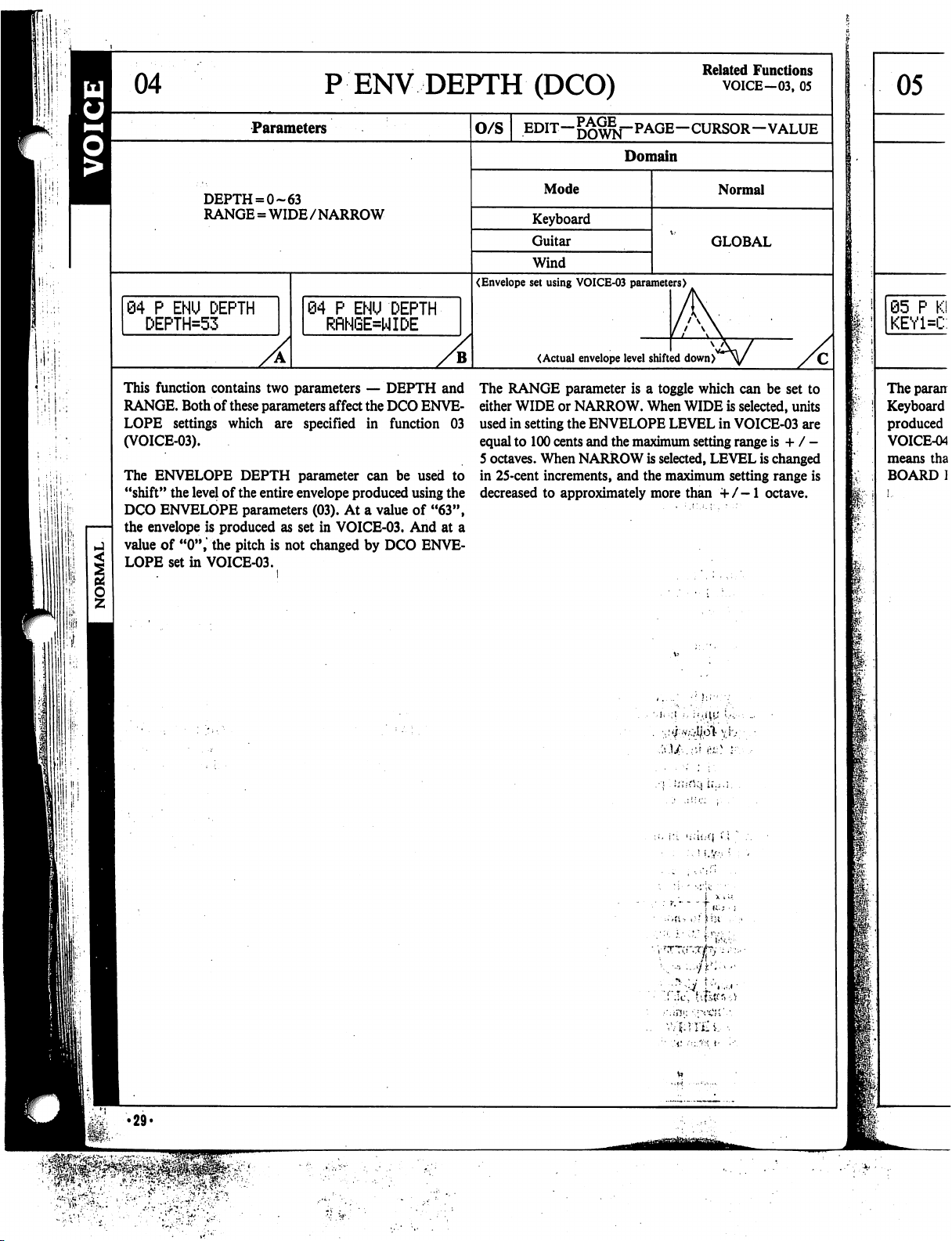
PENV
DEPTH
(DCO)
Related
Functions
VOICE-03,
05
Parameters
O/S
EDIT—
—CURSOR—VALUE
Domain
DEPTH
= 0-63
RANGE
=
WIDE/NARROW
Mode
Keyboard
Guitar
Wind
Normal
GLOBAL
04
P
ENU
DEPTH
DEPTH=53
(Envelope
set
using
VOICE-03
parameters)
84
P
ENU
DEPTH
RRNGE=WIDE
(Actual
envelope
level
shifted
down)
This
function
contains
two
parameters
—
DEPTH
and
RANGE.
Both
of
these
parameters
affect
the
DCO
ENVE
LOPE
settings
which
are
specified
in
function
03
(VOICE-03).
The
ENVELOPE
DEPTH
parameter
can
be
used
to
"shift"
the
level
of
the
entire
envelope
produced
using
the
DCO
ENVELOPE
parameters
(03).
At
a
value
of
"63",
the
envelope
is
produced
as
set
in
VOICE-03.
And
at
a
value
of
"0",
the
pitch
is
not
changed
by
DCO
ENVE
LOPE
set
in
VOICE-03.
The
RANGE
parameter
is
a
toggle
which
can
be
set
to
either
WIDE
or
NARROW.
When
WIDE
is
selected,
units
used
in
setting
the
ENVELOPE
LEVEL
in
VOICE-03
are
equal
to
100
cents
and
the
maximum
setting
range
is
+
/
-
5
octaves.
When
NARROW
is
selected,
LEVEL
is
changed
in
25-cent
increments,
and
the
maximum
setting
range
is
decreased
to
approximately
more
than
+/-1
octave.
I
I
'.liii-rMi
U.,.;.
I
l!
!;
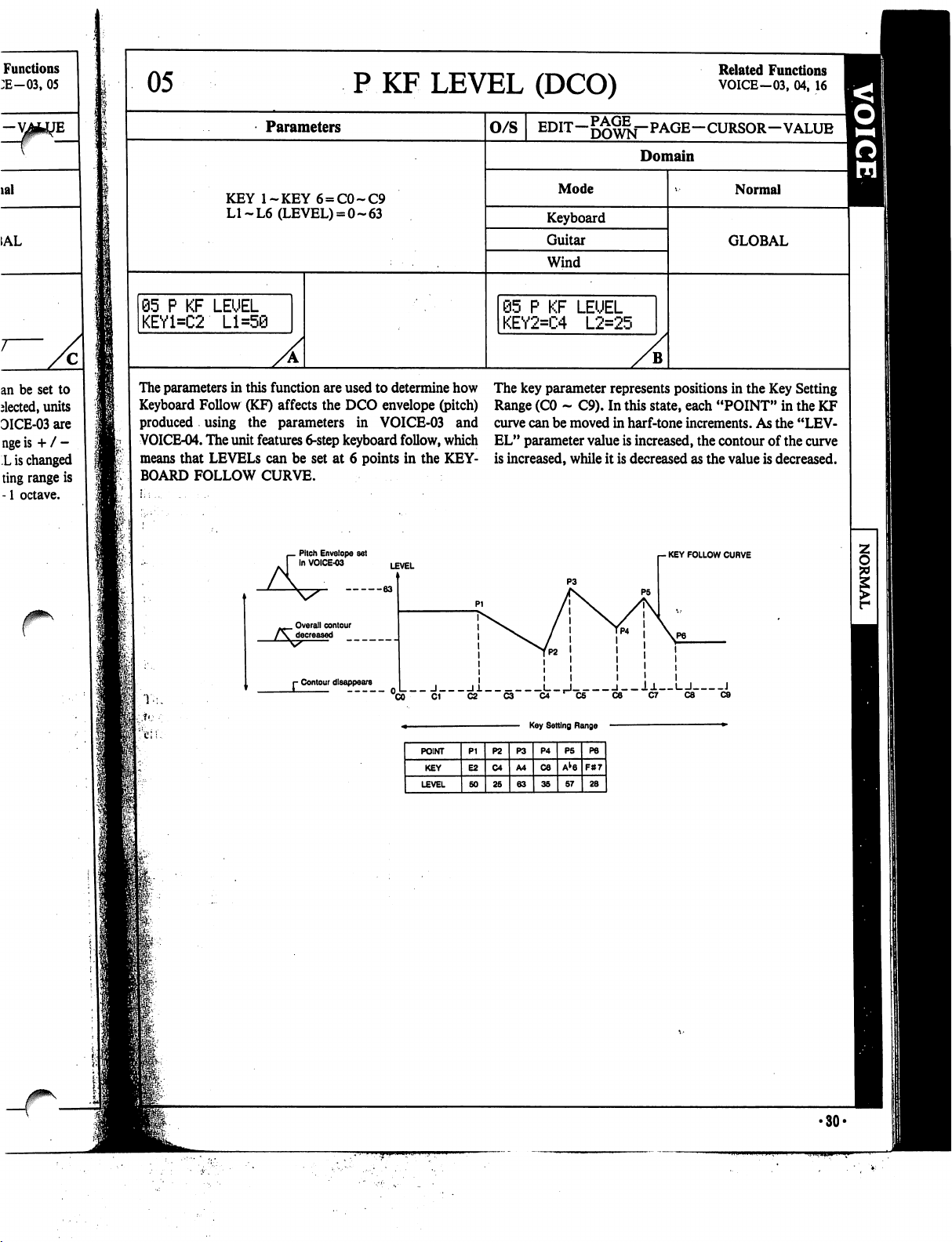
Functions
:E-03,
05
lal
=
1AL
an be
set
to
elected,
units
DICE-03
are
nge
is
+
/
-
L
is
changed
ting
range
is
-1
octave.
05
P
KF
LEVEL
(DCO)
Related
Functions
VOICE-03,
04,
16
Parameters
KEY
l~KEY6
=
C0~C9
LI~L6
(LEVEL)
=
0-63
05
P
KF
LEUEL
KEY1=C2
Ll=5@
O/S
Domain
Mode
Keyboard
Guitar
Wind
@5
P
KF
LEUEL
KEY2=C4
L2=25
B
Normal
GLOBAL
The
parameters
in
this
function
are
used
to
determine
how
Keyboard
Follow
(KF)
affects
the
DCO
envelope
(pitch)
produced
using
the
parameters
in
VOICE-03
and
VOICE-04.
The
unit features
6-step
keyboard
follow,
which
means
that
LEVELS
can
be
set
at
6
points
in
the
KEY
BOARD
FOLLOW
CURVE.
Pitch
Envelope
set
In
VOICE-03
The
key
parameter
represents
positions
in
the
Key
Setting
Range
(CO
-
C9).
In
this
state,
each
"POINT"
in
the
KF
curve
can
be
moved
in
harf-tone
increments.
As
the
"LEV
EL"
parameter
value
is
increased,
the
contour
of
the
curve
is
increased,
while
it
is
decreased
as
the
value
is
decreased.
-
KEY
FOLLOW
CURVE
Overall
contour
r
Contour
disappears
_
J
11
L_,J
l__l±
I
I
J
 Loading...