


CPS-85
POWER |
|
VOLUME |
TRANSPOSE |
DIGITAL EFFECT |
|
TONE |
|
|
|
|
MEMORY |
|
|
||
OFF |
ON |
MIN |
MAX |
F G A A B B C C D E E F |
PIANO 1 |
E. PIANO 1 |
HARPSI- |
PIPE |
STRINGS |
SELECT |
SONG A |
|
|
CONTROL |
DEMO |
|
CHORD |
ORGAN |
|
|
|||||||||||
|
|
|
|
|
PIANO 2 |
E. PIANO 2 |
VIBRA- |
JAZZ |
SYNTH- |
|
SONG B |
RECORD |
STOP |
START |
|
|
|
|
|
|
|
|
PHONE |
ORGAN |
STRINGS |
|
|
|
|
|
|
1 |
5 |
10 |
15 |
20 |
25 |
CPS-85
ELECTRONIC KEYBOARD
|
CONTENTS |
|
Page |
Specifications ............................................................................................................................................ |
1 |
Block Diagram ........................................................................................................................................... |
3 |
Circuit Description ..................................................................................................................................... |
4 |
Major Waveforms .................................................................................................................................... |
11 |
Printed Circuit Boards ............................................................................................................................. |
12 |
Schematic Diagrams ............................................................................................................................... |
13 |
Exploded View .................................................................................................................. |
..................... 19 |
Parts List ................................................................................................................................................. |
21 |
|
|
SPECIFICATIONS |
GENERAL |
|
|
Keyboard: |
88 full size keys with initial touch response |
|
Polyphony: |
24 notes maximum |
|
Tones: |
10 (with layering) |
|
Tuning curves: |
3 types (preset for each tone) |
|
Digital effects: |
REVERB |
|
Demo tunes |
|
|
Number of tunes: |
10 |
|
Titles: |
1. |
Grande valse brillante |
|
2. |
Turkish March |
|
3. |
One-Eighty |
|
4. |
Opaque Mist |
|
5. |
Harmonious blacksmith |
|
6. |
Dream Sequence |
|
7. |
Fugue in G minor |
|
8. |
Moveable Blues |
|
9. |
Rainbow |
|
10. |
Ave Maria |
Playback: |
Repeat sequential play of all tunes; playback always starts from begin- |
|
|
ning of tune |
|
Manual memory |
|
|
Type: |
Real-time recording and playback |
|
Number of songs: |
2 (SONG A, SONG B) |
|
Capacity: |
Approximately 1,200 notes (SONG A + SONG B) |
|
Back-up: |
Power supplied by batteries or AC adaptor |
|
Pedal: |
Damper |
|
Other features |
Transpose (±1 octave, semitone steps) |
|
|
Tuning (adjustable, A4 = 440 Hz ± 50 cents) |
|
MIDI: |
8-channel multi-timbre reception |
|
Speakers: |
14 cm × 2 (6 W + 6 W) |
|
Terminals: |
PHONES (standard stereo jack × 1) |
|
|
LINE OUT (standard mono jack × 2) |
|
|
|
Output impedance: 1.0 KΩ |
Output voltage: 1.5 V (RMS) MAX
LINE IN (standard mono jack × 2)
Input impedance: 47 KΩ
Sensitivity: 200 mV
MIDI OUT/IN (DIN jack × 2)
— 1 —
|
DAMPER PEDAL (standard mono jack × 1) |
|
DC 12 V (DC jack × 1) |
Power supply |
Dual power supply system |
Batteries: |
6 D-size batteries |
Battery life: |
Approximately 4 hours on manganese batteries |
AC adaptor: |
AD-12 |
Auto power off: |
Turns power off approximately 5 minutes after last key operation. |
|
Enabled under battery power only, can be disabled manually. |
Power consumption: |
18 W |
Dimensions (HWD): |
100 × 1372 × 414 mm (without stand) |
|
(3-15/16 × 54-1/16 × 16-5/16 inches) |
Weight: |
Without stand and excluding batteries 16.8 kg (37.1 lbs) |
ELECTRICAL
Current drain with 12 V DC: |
|
240 mA ± 20 % |
No sound output |
|
|
Maximum volume |
|
2050 mA ± 20 % |
with 24 keys from C1 to B2 pressed in Jazz organ tone |
|
|
Volume: maximum, Touch response: maximum |
|
|
Phone output level (Vrms with 8 Ω load each channel): |
|
60 mV ± 20 % |
with key E3 pressed in Jazz organ tone |
L-ch |
|
Speaker output level (Vrms with 4 Ω load each channel): |
R-ch |
65 mV ± 20 % |
|
860 mV ± 20 % |
|
with key E3 pressed in Jazz organ tone |
L-ch |
|
Lineout output level (Vrms with 47 kΩ load each channel): |
R-ch |
920 mV ± 20 % |
|
140 mV ± 20% |
|
with key B5 pressed in Jazz organ tone |
L-ch |
|
|
R-ch |
160 mV ± 20% |
Minimum operating voltage: |
|
6.5 V |
— 2 —
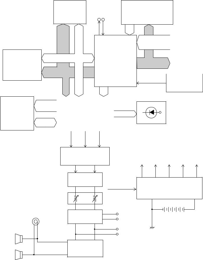
BLOCK DIAGRAM
|
Working Storage |
MIDI |
|
|
|
|
|
|
RAM (64K-bit) |
Buttons |
|
||||
|
LSI2 |
|
OUT IN |
|
|||
|
|
|
|
|
|
||
|
HY6264ALLJ-70 |
|
|
|
|
|
|
|
MA0 |
MD0 |
KI0 ~ KI2 |
FI0 ~ FI10 |
|
|
|
|
|
|
|||||
|
~ |
~ |
|
|
|||
|
|
|
|
||||
|
MA12 |
MD7 |
|
SI0 ~ SI10 |
|
|
|
|
|
|
CPU |
|
|
Keyboard |
|
|
|
|
|
|
|
|
|
Sound Source ROM |
MD0 ~ MD15 |
LSI4 |
|
|
|
|
|
(8M-bit) |
|
|
KC0 ~ KC7 |
|
|
||
LSI3 |
|
|
GT913F |
|
|
|
|
MX23C1610MC-12 |
MA1 ~ MA19 |
|
|
|
|
|
|
|
|
|
|
|
|||
Reset IC
IC 1
RN5VD35AA
MA0, MA1 |
BCK, SO, LRCK |
EA0 ~ Effect RAM EA14 (256K-bit)
LSI5
TC55257DFL-70L EIO0 ~ EIO7
Output
Speakers
DSP |
|
LEDs |
LSI1 |
|
VDD |
|
|
|
HG51B277FB |
|
SONGA |
|
SONGB |
|
|
|
|
|
|
DIGITAL EFFECT |
|
|
|
LRCK SO |
BCK |
SELECT |
STOP |
D/A Converter |
|
|
LSI6 |
VDD |
VCC AVDD AVCC LVDD |
UPD6379GR |
||
Rmel |
Lmel |
|
Filter |
|
|
IC104 |
POWER (APO) |
Power Supply Circuit |
|
||
|
Q101 ~ Q106 |
|
|
From CPU |
|
Main |
D108, D110, D111 |
|
|
|
|
Volume |
|
|
Pre. Amp. |
Line In |
6 × D-size batteries |
IC103 |
|
AC adaptor AD-12 |
|
Line Out |
|
Power Amplifier |
|
|
IC101 |
|
|
LA4620 |
|
|
— 3 —
CIRCUIT DESCRIPTION
KEY MATRIX
|
KC0 |
KC1 |
KC2 |
KC3 |
KC4 |
KC5 |
KC6 |
KC7 |
|
|
|
|
|
|
|
|
|
|
|
FI0 |
A0 (1) |
A#0 (1) |
B0 (1) |
C1 (1) |
C#1 (1) |
D1 (1) |
D#1 (1) |
E1 (1) |
|
|
|
|
|
|
|
|
|
|
|
SI0 |
A0 (2) |
A#0 (2) |
B0 (2) |
C1 (2) |
C#1 (2) |
D1 (2) |
D#1 (2) |
E1 (2) |
|
|
|
|
|
|
|
|
|
|
|
FI1 |
F1 (1) |
F#1 (1) |
G1 (1) |
G#1 (1) |
A1 (1) |
A#1 (1) |
B1 (1) |
C2 (1) |
|
|
|
|
|
|
|
|
|
|
|
SI1 |
F1 (2) |
F#1 (2) |
G1 (2) |
G#1 (2) |
A1 (2) |
A#1 (2) |
B1 (2) |
C2 (2) |
|
|
|
|
|
|
|
|
|
|
|
FI2 |
C#2 (1) |
D2 (1) |
D#2 (1) |
E2 (1) |
F2 (1) |
F#2 (1) |
G2 (1) |
G#2 (1) |
|
|
|
|
|
|
|
|
|
|
|
SI2 |
C#2 (2) |
D2 (2) |
D#2 (2) |
E2 (2) |
F2 (2) |
F#2 (2) |
G2 (2) |
G#2 (2) |
|
|
|
|
|
|
|
|
|
|
|
FI3 |
A2 (1) |
A#2 (1) |
B2 (1) |
C3 (1) |
C#3 (1) |
D3 (1) |
D#3 (1) |
E3 (1) |
|
|
|
|
|
|
|
|
|
|
|
SI3 |
A2 (2) |
A#2 (2) |
B2 (2) |
C3 (2) |
C#3 (2) |
D3 (2) |
D#3 (2) |
E3 (2) |
|
|
|
|
|
|
|
|
|
|
|
FI4 |
F3 (1) |
F#3 (1) |
G3 (1) |
G#3 (1) |
A3 (1) |
A#3 (1) |
B3 (1) |
C4 (1) |
|
|
|
|
|
|
|
|
|
|
|
SI4 |
F3 (2) |
F#3 (2) |
G3 (2) |
G#3 (2) |
A3 (2) |
A#3 (2) |
B3 (2) |
C4 (2) |
|
|
|
|
|
|
|
|
|
|
|
FI5 |
C#4 (1) |
D4 (1) |
D#4 (1) |
E4 (1) |
F4 (1) |
F#4 (1) |
G4 (1) |
G#4 (1) |
|
|
|
|
|
|
|
|
|
|
|
SI5 |
C#4 (2) |
D4 (2) |
D#4 (2) |
E4 (2) |
F4 (2) |
F#4 (2) |
G4 (2) |
G#4 (2) |
|
|
|
|
|
|
|
|
|
|
|
FI6 |
A4 (1) |
A#4 (1) |
B4 (1) |
C5 (1) |
C#5 (1) |
D5 (1) |
D#5 (1) |
E5 (1) |
|
|
|
|
|
|
|
|
|
|
|
SI6 |
A4 (2) |
A#4 (2) |
B4 (2) |
C5 (2) |
C#5 (2) |
D5 (2) |
D#5 (2) |
E5 (2) |
|
|
|
|
|
|
|
|
|
|
|
FI7 |
F5 (1) |
F#5 (1) |
G5 (1) |
G#5 (1) |
A5 (1) |
A#5 (1) |
B5 (1) |
C6 (1) |
|
|
|
|
|
|
|
|
|
|
|
SI7 |
F5 (2) |
F#5 (2) |
G5 (2) |
G#5 (2) |
A5 (2) |
A#5 (2) |
B5 (2) |
C6 (2) |
|
|
|
|
|
|
|
|
|
|
|
FI8 |
C#6 (1) |
D6 (1) |
D#6 (1) |
E6 (1) |
F6 (1) |
F#6 (1) |
G6 (1) |
G#6 (1) |
|
|
|
|
|
|
|
|
|
|
|
SI8 |
C#6 (2) |
D6 (2) |
D#6 (2) |
E6 (2) |
F6 (2) |
F#6 (2) |
G6 (2) |
G#6 (2) |
|
|
|
|
|
|
|
|
|
|
|
FI9 |
A6 (1) |
A#6 (1) |
B6 (1) |
C7 (1) |
C#7 (1) |
D7 (1) |
D#7 (1) |
E7 (1) |
|
|
|
|
|
|
|
|
|
|
|
SI9 |
A6 (2) |
A#6 (2) |
B6 (2) |
C7 (2) |
C#7 (2) |
D7 (2) |
D#7 (2) |
E7 (2) |
|
|
|
|
|
|
|
|
|
|
|
FI10 |
F7 (1) |
F#7 (1) |
G7 (1) |
G#7 (1) |
A7 (1) |
A#7 (1) |
B7 (1) |
C8 (1) |
|
|
|
|
|
|
|
|
|
|
|
SI10 |
F7 (2) |
F#7 (2) |
G7 (2) |
G#7 (2) |
A7 (2) |
A#7 (2) |
B7 (2) |
C8 (2) |
|
|
|
|
|
|
|
|
|
|
|
|
|
|
|
HARPSIC- |
PIPE |
STRINGS/ |
|
|
|
KI0 |
DIGITAL |
PIANO 1/ |
E.PIANO 1/ |
HORD/ |
ORGAN/ |
|
SONG A/ |
||
SYNTH |
SELECT |
||||||||
EFFECT |
PIANO 2 |
E.PIANO 2 |
VIBRAPH- |
JAZZ |
SONG B |
||||
|
STRINGS |
|
|||||||
|
|
|
|
ONE |
ORGAN |
|
|
||
|
|
|
|
|
|
|
|||
|
|
|
|
|
|
|
|
|
|
KI1 |
RECORD |
CONTROL |
DEMO |
TRANSPO- |
TRANSPO- |
TRANSPO- |
TRANSPO- |
TRANSPO- |
|
SE F# |
SE G# |
SE A# |
SE D |
SE E |
|||||
|
|
|
|
||||||
|
|
|
|
|
|
|
|
|
|
KI2 |
STOP |
START |
TRANSPO- |
TRANSPO- |
TRANSPO- |
TRANSPO- |
|
|
|
SE G |
SE A |
SE B |
SE C# |
|
|
||||
|
|
|
|
|
|||||
|
|
|
|
|
|
|
|
|
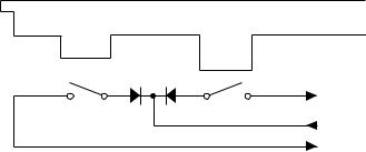
Note: Each key has two contacts,
the first conatct (1) and second contact (2).
Key
|
FI |
Second contact (2) |
First contact (1) |
|
KC |
|
SI |
— 4 —
NOMENCLATURE OF KEYS
A#0 |
C#1 D#1 |
F#1G#1A#1 |
C#2 D#2 |
F#2 G#2 A#2 |
C#3 D#3 |
F#3 G#3 A#3 |
C#4 D#4 |
F#4 G#4 A#4 |
C#5 D#5 |
F#5 G#5 A#5 |
C#6 D#6 |
F#6 G#6 A#6 |
C#7 D#7 |
F#7 G#7 A#7 |
A0 B0 C1 D1 E1 F1 G1 A1 B1 C2 D2 E2 F2 G2 A2 B2 C3 D3 E3 F3 G3 A3 B3 C4 D4 E4 F4 G4 A4 B4 C5 D5 E5 F5 G5 A5 B5 C6 D6 E6 F6 G6 A6 B6 C7 D7 E7 F7 G7 A7 B7 C8
POWER SUPPLY CIRCUIT
The power supply circuit generates five voltages as shown in the following table. VDD voltage is always generated. The others are controlled by POWER signal from the CPU.
Name |
Voltage |
For operation of |
|
|
|
VDD |
+5 V |
CPU, Reset IC, DSP, Sound source ROM, Working storage RAM, Effect RAM |
|
|
|
AVDD |
+5 V |
DAC, Line in jacks |
|
|
|
LVDD |
+5 V |
Pilot lamp |
|
|
|
VCC |
+9 V |
Line out jacks, Power amplifier |
|
|
|
AVCC |
+9 V |
Pre Amp. |
|
|
|
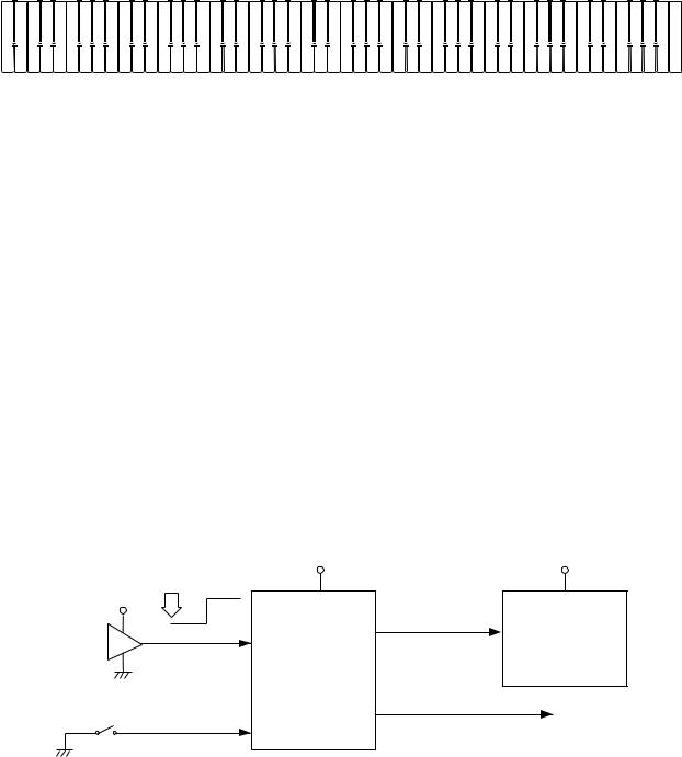
RESET CIRCUIT
When batteries are set or an AC adapter is connected, the reset IC provides a low pulse to the CPU. The CPU then initializes its internal circuit, and clears the working storage RAM.
When the power switch is pressed, the CPU receives a low level signal. The CPU sends POWER signal to the power supply circuit, also sends a reset signal to the DSP.
When the keyboard is powered by batteries and no operation is made for six minutes, CPU drops signal POWER to shut all the voltage except VDD off.
Battery set |
VDD |
|
|
||
VDD |
|
|
RESET |
PLE |
|
Reset IC |
CPU |
|
LSI4 |
||
IC1 |
||
GT913F |
||
RN5VD35AA |
||
|
||
Power switch |
SCKO |
|
|
||
|
NMI |
|
VDD |
Reset signal |
DSP |
|
|
|
LSI1 |
|
HG51B277FB |
POWER |
|
To power supply circuit |
|
— 5 —
CPU (LSI4: GT913F)
The 16-bit CPU contains a 1k-byte RAM, three 8-bit I/O ports, two timers, a key controller and serial interfaces. The CPU detects key velocity by counting the time between first-key input signal FI and second-key SI from the keyboard. The CPU reads sound data and velocity data from the sound source ROM in accordance with the selected tone; the CPU can read rhythm data simultaneously when a rhythm pattern is selected. Then the CPU provides 16-bit serial sound data to the DSP. The CPU also controls MIDI input/output and stores sequencer data into the working storage RAM.
The following table shows the pin functions of LSI4.
Pin No. |
Terminal |
In/Out |
Function |
|
1 |
TXD0 |
Out |
MIDI signal output |
|
|
|
|
|
|
2 |
RXD0 |
In |
MIDI signal input |
|
|
|
|
|
|
3 |
SCK0 |
Out |
POWER (APO; Auto Power OFF) signal output |
|
|
|
|
|
|
4 |
TXD1 |
— |
Not used. Connected to ground. |
|
|
|
|
|
|
5 |
RXD1 |
In |
Power ON signal input |
|
|
|
|
|
|
6 |
SCK1 |
Out |
1 MHZ synchronizing pulse output |
|
|
|
|
|
|
7 ~ 9 |
AVCC, AN0, |
— |
Not used. Connected to ground. |
|
AN1 |
||||
|
|
|
||
10 |
AGND |
In |
Ground (0 V) source |
|
|
|
|
|
|
11 |
BCK |
Out |
Bit clock output |
|
|
|
|
|
|
12 |
SO |
Out |
Serial sound data output |
|
|
|
|
|
|
13 |
LRCK |
Out |
Word clock output |
|
|
|
|
|
|
14 |
GND |
In |
Ground (0 V) source |
|
|
|
|
|
|
15, 16 |
XLT0, XLT1 |
In/Out |
24 MHz clock input/output |
|
|
|
|
|
|
17 |
VCC |
In |
+5 V source |
|
|
|
|
|
|
18, 19 |
MOD0, MOD1 |
In |
Mode selection terminal. Connected to ground. |
|
|
|
|
|
|
20 |
RSTB |
In |
Reset signal input |
|
|
|
|
|
|
21 |
NMI |
In |
Power ON signal input |
|
|
|
|
|
|
22 |
INT |
— |
Connected to ground |
|
|
|
|
|
|
23 ~ 30 |
FI0 ~ FI3 |
In |
Terminal for key input signal |
|
SI0 ~ SI3 |
||||
|
|
|
||
|
|
|
|
|
31 ~ 38 |
KC0 ~ KC7 |
Out |
Terminal for key scan signal |
|
|
|
|
|
|
39 ~ 52 |
FI4 ~ FI10 |
In |
Terminal for key input signal |
|
SI4 ~ SI10 |
||||
|
|
|
||
|
|
|
|
|
53 ~ 55 |
KI0 ~ KI2 |
In |
Terminal for button input signal |
|
|
|
|
|
|
56 |
MWNB |
Out |
Write enable signal for the DSP |
|
|
|
|
|
|
57 ~ 76 |
MA0 ~ MA19 |
Out |
Address bus |
|
|
|
|
|
|
77 |
MCSB0 |
Out |
Chip enable signal output for the sound source ROM |
|
|
|
|
|
|
78 |
MCSB1 |
Out |
Not used |
|
|
|
|
|
|
79 |
MCSB2 |
Out |
Chip enable signal output for the DSP |
|
|
|
|
|
|
80 |
VCC |
In |
+5 V source |
|
|
|
|
|
|
81 |
GND |
In |
Ground (0 V) source |
|
|
|
|
|
|
82 |
MRDB |
Out |
Read enable signal output for the sound source ROM |
|
|
|
|
|
|
83 ~ 98 |
MD0 ~ MD15 |
In/Out |
Data bus |
|
|
|
|
|
|
|
|
|
When the keyboard is powered by an AC adaptor, the terminal |
|
99 |
PLE |
In |
becomes 0 volt so that the CPU does not send auto power off signal |
|
|
|
|
to the power supply circuit. |
|
100 |
P17 |
In |
Pedal input |
|
|
|
|
|
— 6 —
DIGITAL SIGNAL PROCESSOR (LSI1: HG51B227FB)
The DSP receives 16-bit serial sound data from the CPU and adds the selected effect to the sound data using the effect RAM. Then the DSP provides the sound data to the DAC. The DSP also drives LEDs.
The following table shows the pin functions of LSI1.
Pin No. |
Terminal |
In/Out |
Function |
|
|
|
|
|
|
1 ~ 4, 80 |
PB0 ~ PB4 |
— |
Not used.Connected to ground. |
|
|
|
|
|
|
5 |
SO |
Out |
Serial sound data output for the DAC |
|
|
|
|
|
|
6 |
WCKO |
Out |
Word clock output for the DAC |
|
|
|
|
|
|
7 |
VDD3 |
In |
+5 V source |
|
|
|
|
|
|
8 |
TEST |
— |
Not used |
|
|
|
|
|
|
9 |
RESB |
In |
Reset signal input |
|
|
|
|
|
|
10 |
VSS2 |
In |
Ground (0 V) source |
|
|
|
|
|
|
11, 12 |
XIN, XOUT |
In/Out |
16 MHz clock input/output |
|
|
|
|
|
|
13 |
WCKI |
In |
Word clock input from the CPU |
|
|
|
|
|
|
14 |
SI |
In |
Serial sound data input from the CPU |
|
|
|
|
|
|
15 |
BCKI |
In |
Bit clock input from the CPU |
|
|
|
|
|
|
16 |
SINC |
In |
1 MHz synchronizing pulse input |
|
|
|
|
|
|
17 |
VDD2 |
In |
+5 V source |
|
|
|
|
|
|
18 ~ 25 |
IO0 ~ IO7 |
In/Out |
Data bus |
|
|
|
|
|
|
26 |
RCEB |
Out |
Chip enable signal output for the working storage RAM |
|
|
|
|
|
|
27 |
VSS3 |
In |
Ground (0 V) source |
|
|
|
|
|
|
28 |
AD1 |
In |
Address bus |
|
|
|
|
|
|
29 |
OEB |
— |
Not used.Connected to ground. |
|
|
|
|
|
|
30 |
WEB |
In |
Write enable signal |
|
|
|
|
|
|
31 |
VDD3 |
In |
+5 V source |
|
|
|
|
|
|
32 |
CE2 |
In |
Chip enable signal input. High active. |
|
|
|
|
|
|
33 |
AD0 |
In |
Address bus |
|
|
|
|
|
|
34 |
CE1B |
In |
Chip enable signal input. Low active. |
|
|
|
|
|
|
35 ~ 41, 43 |
EIO0 ~ EIO7 |
In/Out |
Data bus for the effect RAM |
|
|
|
|
|
|
42 , 44, 46 ~ 48, |
EA0 ~ EA14 |
Out |
Address bus for the effect RAM |
|
51 ~ 59, 61 |
||||
|
|
|
||
45 |
ECEB |
Out |
Chip enable signal output for the effect RAM |
|
|
|
|
|
|
49 |
EOEB |
Out |
Read enable signal output for the effect RAM |
|
|
|
|
|
|
50 |
VSS3 |
In |
Ground (0 V) source |
|
|
|
|
|
|
60 |
EWEB |
Out |
Write enable signal output for the effect RAM |
|
|
|
|
|
|
62, 66, 70, 74, 78 |
VSS2 |
In |
Ground source |
|
|
|
|
|
|
63, 67, 71, 75, 79 |
VDD2 |
In |
+5 V source |
|
|
|
|
|
|
64, 65, 68, 69, |
PA0 ~ PA5 |
Out |
Button scan signal output |
|
72, 73 |
||||
|
|
|
||
76, 77 |
PA6/7 |
Out |
Not used |
|
|
|
|
|
— 7 —
 Loading...