


50TC
50TC
Cooling Only/Electric Heat Packaged Rooftop
3to12.5NominalTons
Product Data
This product has been designed and manufac tured t o
meet Energy Star® criteria for energy efficiency.
However, pr oper ref rigerant charge and proper ai r f low
are critical to achieve rated capacity and efficiency.
Installation of this product should follow all
manufacturer’s refrigerant charging and air flow
instructions. Failure to confirm proper charge and
air fl ow may reduce energ y efficienc y and shorten
equipment life.
C08613
the environmentally sound refrigerant

TABLE OF CONTENTS
PAGE
PAGE
FEATURES AND BENEFITS 3....................
MODEL NUMBER NOMENCLATURE 4............
FACTORY OPTIONS & ACCESSORIES 5...........
ARI CAPACITY RATING 8.......................
SOUND PERFORMANCE 10......................
PHYSICAL DA TA 11.............................
BASE UNIT DIMENSIONS 23.....................
APPLICATION DATA 29.........................
50TC
COOLING TABLES 31...........................
STATIC PRESSURE TABLES 41...................
F AN PERFORMANCE 42.........................
OUTDOOR AIR INTAKE & EXHAUST PERF 54.....
ELECTRICAL INFO 55...........................
MCA / MOCP 59................................
TYPICAL WIRING DIAGRAM 79..................
GUIDE SPECIFICATIONS 84......................
Your Carrier rooftop unit (RTU) was designed by customers for customers. With no--strip screw collars, handled access
panels, and more we’ve made your unit easy to install, easy to maintain and easy to use.
Easy to install:
All WeatherMakert units are field--convertible to horizontal air flow; no special adapter curbs or kits are necessary.
Convertible airflow design makes it easy to adjust to unexpected job--site complications. Lighter units make easy
replacement. Carrier 3--12.5 ton 50TC rooftops fit on existing Carrier curbs dating back to 1989. Also, our large control
box gives you room to work and room to mount Carrier accessory controls.
Easy to maintain:
Easy access handles by Carrier provide quick and easy access to all normally serviced components. Our “no--strip” screw
system has superior holding power and guides screws into position while preventing the screw from stripping the unit’s
metal. Take accurate pressure readings by reading condenser pressure with panels on. Simply remove the black, composite
plug, route your gauge line(s) t hrough the hole, and connect them to the refrigeration service valve(s). Now, you can take
refrigeration system pressure readings without affecting the condenser airflow.
Easy to use:
The newly designed, master terminal board by Carrier puts all your connections and troubleshooting points in one
convenient place, standard. Most low voltage connections are made to the same board and make it easy t o find what you’re
looking for and easy to access it. Carrier rooftops have high and low pressure switches, a filter drier, and 2” (51mm) filters
standard.
2

FEATURES AND BENEFITS
S Up to 28% lighter than similar industry units. Lighter rooftops make easier replacement jobs.
S 3--12.5 ton units fit on existing Carrier rooftop curbs making the utility connections the same. This saves time and money
on replacement jobs.
S Standardized components and layout. Standardized components and c ontrols m ake service and stocking parts easier.
S Scroll compressors on all units. This makes service, stocking parts, replacement, and trouble--shooting easier.
S Field convertible airflow (3--12.5 tons). Being able to convert a unit from vertical airflow to horizontal makes it easy to
overcome job site complications.
S Easy --adjust, belt--drive motor available. Carrier provides a factory solution for most points in the fan performance table.
There’s no need for fie ld--supplied drives or motors.
S Provisions for bottom or side condensate drain.
S Capable of thru--the--base or thru--the--curb electrical routing.
S Single--point electrical connection.
S Sloped, com posite drain pan. Sloped, composite drain pan sheds water; and won’t rust.
S Standardized controls and control box layout. Standardized components and controls make stocking parts and service
easier.
S Clean, easy to use control box.
S Color --coded wiring.
S Large, laminated wiring and power wiring drawings which are affixed to unit make troubleshooting easy.
S Single, central terminal board for test and wiring connections.
S Fast--access, handled, panels for easy access to the blower and blower motor, control box, and compressors.
S “No--strip” screw system guides screws into the panel a nd captures them tightly without strippi ng the screw, the panel, or
the unit.
50TC
S Exclusive, newly-- design indoor refrigerant header for easier maintenance and replacement.
S Mechanical cooling (115_Fto25_For46_Cto--4_C) on Direct Digital Controller (DDC) (PremierLinkt or RTU--MP
controller).
S Mechanical cooling (115_Fto25_For46_Cto--4_C) on Electro--Mechanical (E/M) models, with winter start kit.
S 2” (51mm) disposable filters on all units.
S Refrigerant filter --drier on each circuit.
S High and low pressure switches. Added reliability with high pressure switch and low pressure switch.
S Factory--installed Humidi--MiZert adaptive dehumidification system.
the environmentally sound refrigerant
This product has been design ed and manufac tured t o
meet Energy Star® criteria for energy efficiency.
However, pr oper ref rigerant charge and proper ai r f low
are critical to achieve rated capacity and efficiency.
Installation of this product should follow all
manufacturer’s refrigerant charging and air flow
instructions. Failure to confirm proper charge and
air fl ow may reduce energ y efficienc y and shorten
equipment life.
3

MODEL NUMBER NOMENCLATURE
123456789101112131415161718
5 0 T C -- A 0 6 A 1 A 5 A 0 A 0 A 0
____ ____ ____
2
2
50TC
Unit Heat Type Brand / Packaging
50 = Cooling/Elec Heat RTU 0=Standard
Tier / Model
TC = Entry tier (with Puron refrigerant) Electrical Options
Heat Size C = N o n --- f u s e d d i sc
--- = N o h e a t D=Thruthebase
Refrig. System Options
A = Standard 1 ---stage cooling Service Options
B = S t a n d a r d 1 --- s ta g e c o o l i n g w / H u m i d i --- M i Z e r 0=None
D = 2 ---stg. cooling compressor w/NOVATION™ 1 = Unpowered convenience outlet
Cooling Tons
04 = 3 Ton Intake / Exhaust Options
05 = 4 Ton A=None
06 = 5 Ton B=Tempeconow/barorelief
07 = 6 Ton F = Enthalpy econo w/ baro relief
08 = 7.5 Ton K = 2 position damper
09 = 8.5 Ton
12 = 10 Ton Base Unit Controls
14 = 12.5 Ton 0 = Electromechanical
Sensor Options 2 = Open protocol DDC controller
A=None
B = RA smoke detector Design Rev
C = SA smoke detector Factory assigned
D=RA&SAsmokedetector
E=CO2sensor Voltage
F = RA smoke detector & CO
G = SA smoke detector & CO
H=RA&SAsmokedetector&CO
1=LTL
A=None
F = Non--- fused & thru the base
2 = Powered convenience outlet
1 = PremierLink DDC controller
1 = 575/3/60
3 = 208 ---230/1/60
2
5 = 208 ---230/3/60
6 = 460/3/60
Indoor Fan Options 1 --- S t a g e C o o l i n g C o i l O p t i o n s ( O u t d o o r --- I n d o o r )
1 = Standard static option A = Al/Cu --- Al/Cu
2 = Medium static option B = P r e c o a t A l / C u --- A l / C u
3 = High static option C = E c o a t A l / C u --- A l / C u
D=EcoatAl/Cu--- EcoatAl/Cu
E = Cu/C u --- Al/Cu
F = Cu/Cu --- Cu/Cu
M = A l / C u --- A l/ C u --- L o u v e r e d H a i l G u a r d s
N = P r e c o a t A l / C u --- A l / C u --- L o u v e r e d H a i l G u a r d s
P = E c o a t A l / C u --- A l / C u --- L o u v e r e d H a i l G u a r d s
Q = E c o a t A l / C u --- E c o a t A l / C u --- L o u v e r e d H a i l G u a r d s
R = C u / C u --- A l / C u --- L o u v e r e d H a i l G u a r d s
S = C u / C u --- C u / C u --- L o u v e r e d H a i l G u a r d s
2 --- S t a g e C o o l i n g C o i l O p t i o n s ( O u t d o o r --- I n d o o r )
G = Al/Al --- Al/Cu
H = Al/Al --- Cu/Cu
J = A l / A l --- E --- c o a t A l / C u
K = E --- c o a t A l/ A l --- A l / C u
L = E --- c o a t A l / A l --- E --- c o a t A l / C u
T = A l / A l --- A l / C u --- L o u v e r e d H a i l G u a r d s
U = A l / A l --- C u / C u --- L o u v e r e d H a i l G u a r d s
V = A l / A l --- E --- c o a t A l / C u --- L o u v e r e d H a i l G u a r d s
W = E --- c oa t A l/ A l --- Al / C u --- L o u v e r e d H a i l G u a r d s
X = E --- c o a t A l/ A l --- E --- c o a t A l / C u --- L o u v e r e d H a i l G u a r d s
4

Table 1 – FACTORY--INSTALLED OPTIONS AND FIELD-- INSTALLED ACCESSORIES
FACTO RY
CATEGORY ITEM
Cabinet Thru--- the--- base electrical connections X X
1
1
Coil Options
Cu/Cu indoor and/or outdoor coils
Pre--- coated outdoor coils
1
Premium, E --- coated outdoor coils
Humidity Control Humdi ---MiZer™ Adaptive Dehumidification System X
Condenser Protection Condenser coil hail guard (louvered design) X X
Thermostats, temperature sensors, and subbases X
PremierLink DDC communicating controller X X
Controls
RTU ---MP open - -- protocol controller X
Smoke detector (supply and/or return air) X
Time Guard II compressor delay control circuit X
Phase Monitor X
EconoMi$er IV (for electro --- mechanical controlled RTUs) X X
EconoMi$er2 (for DDC controlled RTUs) X X
Economizers
& Outdoor Air
Dampers
Motorized 2 position outdoor ---air damper X X
Manual outdoor--- air damper (25% and 50%) X
Barometric relief
2
Power exhaust X
3
3
3
Economizer Sensors &
IAQ Devices
Electric Heat
Single dry bulb temperature sensors
Differential dry bulb temperature sensors
Single enthalpy sensors
Differential enthalpy sensors
3
3
CO2sensor (wall, duct, or unit mounted)
Electric Resistance Heaters X
Single Point Kit X
Indoor Motor & Drive Multiple motor and drive packages X
Low Ambient
Control
Power
Options
Roof Curbs
Winter start kit
Motormaster head pressure controller
Convenience outlet (powered) X
Convenience outlet (unpowered) X
Non -- -fused disconnect X
Roof curb 14” (356mm) X
Roof curb 24” (610mm) X
4
4
INSTALLED
OPTION
X
X
X
X X
X X
X X
X X
INSTALLED
ACCESSORY
FIELD
50TC
X
X
X
X
NOTES:
1. NOVATION™ coils (2 --- stage cooling models 08 ---14): Condenser Coil = E - -- coat, Indoor Coil = Cu/Cu or E --- coat
2. Included with economizer.
3. Sensors for optimizing economizer.
4. See application data for assistance.
5

FACTORY OPTIONS AND/OR ACCESSORIES
Economizer (dry--bulb or enthalpy)
Economizers save money. They bring in fresh, outside air
for ventilation; and provide cool, outside air to cool your
building. This is the preferred method of low--ambient
cooling. W h en coupled to CO
provide even more savings by coupling the ventilation air
to only that amount required.
Economizers are available, installed and tested by the
factory, with either enthalpy or dry--bulb temperature
inputs. There are also models for electromechanical as
well as direct digital controllers. Additional sensors are
available as accessories to optimize the economizers.
Economizers include gravity controlled, barometric relief
equalizes building pressure and ambient air pressures.
This can be a cast effective solution to prevent building
50TC
pressurization.
sensors, Economize r s can
2
CO2Sensor
Improves productivity and saves money by working with
the economizer to intake only the correct amount of
outside air for ventilation. As occupants fill your building,
the CO
CO
When the occupants leave, the CO
the sensor appropriately closes the economizer. This
intelligent control of the ventilation air, called Demand
Control Ventilation (DCV) reduces the overall load on the
rooftop, saving money.
sensor detects their presence through increasing
2
levels, and opens the economizer appropriately.
2
levels decrease, and
2
Power Exhaust with Barometric Relief.
Superior internal building pressure control. This
field--installed accessory may eliminate the need for
costly, external pressure control fans.
PremierLinkt
This CCN controller regulates your rooftop’s performance
to tighter tolerances and expanded limits, as well as
facilitates zoning systems and digital accessories. It also
unites your Carrier HVAC equipment together on one,
coherent CCN network. The PremierLink can be
factory--installed, or easily field-- installed.
RTU--MP, Multi --protocol Controller
Connect the rooftop to an existing BAS without needing
complicated translators or adapter modules using the
RTU--MP controller. This new controller speaks the 4
most common building automation system languages
(Bacnet, Modbus, N2, and Lonworks). Use this controller
when you have an existing BAS.
Time Guard II Control Circuit
This accessory protects your compressor by preventing
short--cycling in the event of some other failure, prevents
the compressor from restarting for 30 seconds after
stopping. Not required with PremierLinkr,RTU--MP,or
authorized commercial thermostats.
Filter or Fan Status Switches
Smoke Detectors
Trust the experts. Smoke detect ors make your application
safer a nd your job easier. Carrier smoke detectors
immediately shut down the rooftop unit when smoke is
detected. They are available, installed by the factory, for
supply air, return air, or both.
Louvered Hail Guards
Sleek, louvered panels protect the condenser coil from
hail damage, foreign objects, and incidental contact.
Convenience Outlet (powered or un--powered)
Reduce service and/or installation costs by including a
convenience outlet in your specification. Carrier will
install this service feature at our factory. Provides a
convenient, 15 amp, 115v GFCI receptacle with “Wet in
Use” cover. The “powered” option allows the installer to
power the outlet from the line side of the disconnect or
load side as required by code. The “unpowered” option is
to be powered from a separate 115/120v power source.
Non--fused Disconnect
This OSHA--compliant, factory--installed, safety switch
allows a service technician to locally secure power to the
rooftop.
Use these differential pressure switches to detect a filter
clog or indoor fan motor failure. When used in
conjunction with a compatible unit controller/thermostat,
the switches will activate an alarm to warn the appropriate
personnel.
Motorized 2--Position Damper
The new Carrier 2--position, motorized outdoor air damper
admits up to 100% outside air. Using reliable, gear--driven
technology, the 2--position damper opens to allow
ventilation air and closes when the rooftop stops, stopping
unwanted infiltration.
Manual OA Damper
Manual outdoor air dampers are an economical way to
bring in ventilation air. The dampers are available in 25%
and 50% versions.
Optional Humidi--MiZert Adaptive
Dehumidification System
Carrier’s Humidi--MiZer adaptive dehumidification
system is an all-- inclusive factory--installed option that can
be ordered with any WeatherMaker 50TC--04--07 rooftop
unit.
This system expands the envelope of operation of
Carrier’s WeatherMaker rooftop products to provide
6

unprecedented flexibility to meet year --round comfort
conditions.
The Humidi--MiZer adaptive dehumidification system has
the industry’s only dual dehumidification mode setting.
The Humidi--MiZer system includes two new modes of
operation.
The WeatherMaker 50TC--04--07 ooftop coupled with the
Humidi--MiZer system is capable of operating in normal
design cooling mode, subcooling mode, and hot gas reheat
mode. Normal design cooling mode is when the unit will
operate under its normal sequence of ope ration by cycling
compressors to maintain comfort conditions.
Subcooling mode will operate to satisfy part load type
conditions when the space requires combined sensible and
a higher proportion of latent load control. Hot Gas Reheat
mode will operate when outdoor temperatures diminish
and the need for latent capacity is required for sole
humidity control. Hot Gas Reheat mode will provide
neutral air for maximum dehumidification operation.
Motormaster Head Pressure Controller
The Motormaster motor controller is a low ambient, head
pressure controller kit that is designed to m aintain the
unit’s condenser head pressure during periods of low
ambient cooling operation. This device should be used as
an alternative to economizer free cooling not when
economizer usage is either not appropriate or desired. The
Motormaster will either cycle the outdoor--fan motors or
operate them at reduced speed to maintain the unit
operation, depending on the model.
Winter Start Kit
The winter start kit by Carrier extends the low ambient
limit of your rooftop to 25_F(--4_C). The kit bypasses the
low pressure switch, preventing nuisance tri pping of the
low pressure switch. Other low ambient precautions may
still be prudent.
Alternate Motors and Drives
Some applications need larger horsepower motors, some
need more airflow, and some need both. Regardless of the
case, your Carrier expert has a factory installed
combination to meet your application. A wide selection of
motors and pulleys (drives) are available , factory
installed, to handle nearly any application.
Thru--the--Base Connections
Thru--the--base connections, available as either an
accessory or as a factory option, are necessary to ensure
proper connection and seal when routing wire and piping
through the rooftop’s basepan and curb. These couplings
eliminate roof penetration and should be considered for
gas lines, main power lines, as well as control power.
Electric Heaters
Carrier offers a full--line of field-- installed accessory
heaters. The heaters are very easy to use, install and are
all pre--engineered and certified.
50TC
7

Table 2 – ARI COOLING RATING TABLES
UNIT
COOLING
STAGES
NOM.
CAPACITY
(TONS)
A04 1 3 34.6 3.1 13.00 11.00 N/A
A05 1 4 45.0 4.0 13.00 11.00 N/A
A06 1 5 59.0 5.5 13.00 10.75 N/A
A07 1 6 70.0 6.4 N/A 11.20 N/A
A08 1 7.5 88.0 8.0 N/A 11.20 N/A
A09 1 8.5 97.0 8.8 N/A 11.20 N/A
A12 1 10 117.0 10.6 N/A 11.20 N/A
NET
COOLING
CAPACITY
(MBH)
POWER (KW)
TABLE 3 – ARI COOLING RATING TABLE 2--STAGE COOLING
NET
COOLING
CAPACITY
(MBH)
POWER (KW)
50TC
UNIT
COOLING
STAGES
NOM.
CAPACITY
(TONS)
D08 2 7.5 83.0 7.4 N/A 11.20 12.0
D12 2 10 114.0 10.1 N/A 11.30 12.6
D14 2 12.5 140.0 12.7 N/A 11.00 11.7
TOTAL
TOTAL
SEER EER IPLV
SEER EER IPLV
LEGEND
ARI --- Air---Conditioning, Heating and Refrigeration
Institute
ASHRAE --- American Society of Heating, Refrigerating
and Air Conditioning, Inc.
EER --- Energy Efficiency Ratio
SEER --- Seasonal Energy Efficiency Ratio
IPLV --- Integrated Part Load Value
NOTES
1. Rated and certified under ARI Standard 210/240 --- 06 or
340/360--- 07, as appropriate.
2. Ratings are based on:
Cooling Standard: 80_F(27_C) db, 67_F(19_C) wb
indoor air temp and 95_F db outdoor air temp.
IPLV Standard:80_F(27_C) db, 67_F(19_C) wb indoor
air temp and 80_F(27_C) db outdoor air temp.
3. All 50TC units comply with ASHRAE 90.1 2001, 2004
Energy Standard for minimum SEER and EER
requirements.
4. Where appropriate, 50TC units comply with US Energy
Policy Act (2005). Refer to state and local codes or visit
the following website: http://bcap ---energy. org to
determine if compliance with this standard pertains to
your state, territory, or municipality.
This product has been design ed and manufac tured t o
meet Energy Star® criteria for energy efficiency.
However, pr oper ref rigerant charge and proper ai r f low
are critical to achieve rated capacity and efficiency.
Installation of this product should follow all
manufacturer’s refrigerant charging and air flow
instructions. Failure to confirm proper charge and
air fl ow may reduce energ y efficienc y and shorten
equipment life.
8
Table 4 – MINIMUM -- MAXIMUM AIRFLOWS ELECTRIC HEAT
UNIT
50TC**04 900 1500 900 1500
50TC**05 1200 2000 1200 2000
50TC**06 1500 2500 1500 2500
50TC**07 1800 3000 1800 3000
50TC**08 2250 3750 2250* 3750
50TC**09 2550 4250 2250* 4250
50TC**12 3000 5000 3000* 5000
50TC**14 3600 6000 3000* 6000
Minimum Maximum Minimum Maximum
* Minimum electric heat CFM exceptions :
UNIT UNIT VOLTAGE HEATER KW UNIT CONFIGURATION
50TC**12
50TC**14
50TC**12
50TC**14
50TC**12
50TC**14
50TC**08
50TC**09
50TC**12
50TC**14
208/230 42.4 Horizontal 3200
208/230 50.0 Horizontal 3200
460 50.0 Horizontal or Vertical 3200
575
COOLING ELECTRIC HEATERS
17.0
34.0 2350
REQUIRED MINIMUM
CFM
50TC
2800
Horizontal or Vertical
9
Table 5 – SOUND PERFORMANCE TABLE
UNIT
A04 1 80 90.6 80.9 80.2 76 74.6 71.3 68.5 63.9
A05 1 81 90.9 84.6 79.5 77.9 76.5 71.1 66.9 62.5
A06 1 78 84.0 82.2 76.3 74.8 72.5 68.8 65.6 61.8
A07 1 78 88.8 81.8 76.9 74.4 73.3 69.8 66.3 62.7
A08 1 82 90.1 82.6 81.0 79.4 77.0 73.0 70.4 66.7
D08 2 82 85.8 84.3 80.5 78.7 76.4 72.7 68.3 65.1
A09 1 83 91.2 86.4 81.9 81.0 78.3 73.9 71.4 67.3
A12 1 82 88.6 85.0 81.6 79.5 77.4 74.1 71.0 66.3
D12 2 82 89.0 83.1 80.5 78.5 75.5 71.6 69.6 69.3
D14 2 87 87.0 85.2 84.6 84.9 82.2 78.4 75.3 72.9
COOLING
STAGES
A --- W E I G H T E D 63 125 250 500 1000 2000 4000 8000
OUTDOOR SOUND (dB)
50TC
LEGEND
dB --- Decibel
NOTES:
1. Outdoor sound data is measure in accordance with ARI
standard 270--- 2008.
2. Measurements are expressed in terms of sound power.
Do not compare these values to sound pressure values
because sound pressure accounts for specific environmental factors which do not match individual applications. Sound power values are independent of the environment and therefore more accurate.
3. A ---weighted sound ratings filter out very high and very
low frequencies, to better approximate the response of
an “average” human ear. A--- weighted measurements for
Carrier units are taken in accordance with 270 ---2008.
10
Table 6 – PHYSICAL DATA (COOLING) 3 -- 6 TONS
50TC*A04 50TC*A05 50TC*A06 50TC*A07
Refrigeration System
#Circuits/#Comp./Type 1/1/Scroll 1/1/Scroll 1/1/Scroll 1/1/Scroll
Puronr refrig. (R--- 410A) charge per circuit A/B (lbs --- oz) 5 --- 1 0 / --- 8 --- 8 / --- 1 0 --- 1 1 / --- 1 4 --- 2 / ---
O p e r a t i n g c h a r g e ( l b s --- o z ) --- H u m id i --- M i Z e r U n i t 8 --- 1 2 14--- 13 1 6 --- 0 2 2 --- 4
Metering Device Acutrol Acutrol Acutrol Acutrol
High--- press. Trip / Reset (psig) 630 / 505 630 / 505 630 / 505 630 / 505
Low--- press. Trip / Reset (psig) 54 / 117 54 / 117 54 / 117 54 / 117
Evap. Coil
Material Cu / Al Cu / Al Cu / Al Cu / Al
Coil type 3/8” RTPF 3/8” RTPF 3/8” RTPF 3/8” RTPF
Rows / FPI 2 / 15 2/15 4/15 4/15
Total Face A r e a (ft2)5.5 5.5 5.5 7.3
Condensate Drain Conn. Size 3/4” 3/4” 3/4” 3/4”
Evap. Fan and Motor
Motor Qty / Drive Type 1/Belt
Max BHP 1.2
RPM Range 560--- 854 560--- 854 770--- 1175 ---
1phase
Standard Static
1phase
Medium Static
3phase
Standard Static
3phase
Medium Static
3phase
High Static
Motor Frame Size 48 48 48 ---
Fan Qty / Type 1/Centrifugal 1/Centrifugal 1/Centrifugal ---
Fan Diameter (in) 10 x 10 10 x 10 10 x 10 ---
Motor Qty / Drive Type 1/Belt 1/Belt 1/Belt ---
Max BHP 1.2 1.2 1.5 ---
RPM Range 770 ---1175 770--- 1175 1035 ---1466 ---
Motor Frame Size 48 48 56 ---
Fan Qty / Type 1/Centrifugal 1/Centrifugal 1/Centrifugal ---
Fan Diameter (in) 10 x 10 10 x 10 10 x 10 ---
Motor Qty / Drive Type 1/Belt 1/Belt 1/Belt 1/Belt
Max BHP 1.2 1.2 1.5 2.4
RPM Range 560--- 854 560--- 854 770--- 1175 1073---1457
Motor Frame Size 48 48 48 56
Fan Qty / Type 1/Centrifugal 1/Centrifugal 1/Centrifugal 1/Centrifugal
Fan Diameter (in) 10 x 10 10 x 10 10 x 10 10 x 10
Motor Qty / Drive Type 1/Belt 1/Belt 1/Belt 1/Belt
Max BHP 1.2 1.2 2.4 2.9*
RPM Range 770 ---1175 770--- 1175 1035 ---1466 1173 --- 1518
Motor Frame Size 48 48 56 56
Fan Qty / Type 1/Centrifugal 1/Centrifugal 1/Centrifugal 1/Centrifugal
Fan Diameter (in) 10 x 10 10 x 10 10 x 10 10 x 10
Motor Qty / Drive Type 1/Belt 1/Belt 1/Belt 1/Belt
Max BHP 2.4 2.4 2.9 3.7
RPM Range 1035--- 1466 1035 --- 1466 1303 --- 1687 1474 ---1788
Motor Frame Size 56 56 56 56
Fan Qty / Type 1/Centrifugal 1/Centrifugal 1/Centrifugal 1/Centrifugal
Fan Diameter (in) 10 x 10 10 x 10 10 x 10 10 x 10
1/Belt 1/Belt ---
1.2 1.2 ---
50TC
Cond. Coil
Total Face A r e a (ft2) 14.6 16.5 16.5 21.3
H u m i d i --- M i Z e r C o i l
Total Face A r e a (ft2)3.9 3.9 3.9 5.2
Cond. fan / motor
Qty / Motor Drive Type 1/ Direct 1/ Direct 1/ Direct 1/ Direct
Fan diameter (in) 22 22 22 22
Filters
RA Filter # / Size (in) 2 / 16 x 25 x 2 2/16x25x2 2/16x25x2 4/16x16x2
OA inlet screen # / Size (in) 1/20x24x1 1/20x24x1 1/20x24x1 1/20x24x1
* 575V motor utilizes 3.7 BHP.
Material Cu / Al Cu / Al Cu / Al Cu / Al
Coil type 3/8” RTPF 3/8” RTPF 3/8” RTPF 3/8” RTPF
Rows / FPI 1 / 17 2/17 2/17 2/17
Material Cu / Al Cu / Al Cu / Al Cu / Al
Rows..Fins/in. 1 / 17 2/17 2/17 2/17
Motor HP / RPM 1/4 / 1100 1/4 / 1100 1/4 / 1100 1/4 / 1100
11

Table 7 – PHYSICAL DATA (COOLING) 7.5 -- 12.5 TONS
50TC*A08 50TC*D08 50TC*A09 50TC*A12 50TC*D12 50TC*D14
Refrigeration System
#Circuits/#Comp./Type 1/1/Scroll 2/2/Scroll 1/1/Scroll 1/1/Scroll 2/2/Scroll 2/2/Scroll
Puronr refrig. (R--- 410A) charge per
High--- press. Trip / Reset (psig) 630 / 505 630 / 505 630 / 505 630 / 505 630 / 505 630 / 505
Low--- press. Trip / Reset (psig) 54 / 117 54 / 117 54 / 117 54 / 117 54 / 117 54 / 117
Evap. Coil
Condensate Drain Conn. Size 3/4” 3/4” 3/4” 3/4” 3/4” 3/4”
Evap. Fan and Motor
50TC
3phase
Standard Static
3phase
Medium Static
c i r c u i t A / B ( l b s --- o z )
Total Face A r e a (ft2)8.9 8.9 11.1 11.1 11.1 11.1
Motor Qty / Drive Type 1/Belt 1/Belt 1/Belt 1/Belt 1/Belt 1/Belt
RPM Range 489--- 747 489--- 747 518--- 733 591 --- 838 591--- 838 652--- 843
Motor Frame Size 56 56 56 56 56 56
Fan Qty / Type 1/Centrifugal 1/Centrifugal 1/Centrifugal 1/Centrifugal 1/Centrifugal 1/Centrifugal
Fan Diameter (in) 15 x 15 15 x 15 15 x 15 15 x 15 15 x 15 15 x 15
Motor Qty / Drive Type 1/Belt 1/Belt 1/Belt 1/Belt 1/Belt 1/Belt
RPM Range 733--- 949 733--- 949 690--- 936 838--- 1084 838--- 1084 838--- 1084
Motor Frame Size 56 56 56 56 56 56
Fan Qty / Type 1/Centrifugal 1/Centrifugal 1/Centrifugal 1/Centrifugal 1/Centrifugal 1/Centrifugal
Fan Diameter (in) 15 x 15 15 x 15 15 x 15 15 x 15 15 x 15 15 x 15
Metering Device Acutrol Acutrol Acutrol Acutrol Acutrol Acutrol
Material Cu / Al Cu / Al Cu / Al Cu / Al Cu / Al Cu / Al
Coil type 3/8” RTPF 3/8” RTPF 3/8” RTPF 3/8” RTPF 3/8” RTPF 3/8” RTPF
Rows / FPI 3 / 15 3/15 3/15 4/15 4/15 4/15
Max BHP 1.7 1.7 1.7 2.4 2.4 2.9*
Max BHP 2.9* 2.9* 2.4 3.7 3.7 3.7
1 3 --- 1 2 / --- 4 --- 6 / 4 --- 6 1 5 --- 4 / --- 2 0 --- 0 / --- 6 --- 0 / 6 --- 0 7 --- 6 / 8 --- 0
Motor Qty / Drive Type 1/Belt 1/Belt 1/Belt 1/Belt 1/Belt 1/Belt
Max BHP 4.7 4.7 3.7 4.7 4.7 4.7
RPM Range 909 --- 1102 909--- 1102 838--- 1084 1022--- 1240 1022--- 1240 1022 ---1240
Motor Frame Size 145TY 145TY 56 145TY 145TY 145TY
3phase
High Static
Cond. Coil
Cond. fan / motor
Filters
Fan Qty / Type 1/Centrifugal 1/Centrifugal 1/Centrifugal 1/Centrifugal 1/Centrifugal 1/Centrifugal
Fan Diameter (in) 15 x 15 15 x 15 15 x 15 15 x 15 15 x 15 15 x 15
Material Cu / Al Al / Al Cu / Al Cu / Al Al / Al Al / Al
Coil type 3/8” RTPF NOVATION™ 3/8” RTPF 3/8” RTPF NOVATION™ NOVATION™
Rows / FPI 2 / 17 1/20 2/17 2/17 1/20 2/20
Total Face A r e a (ft2) 20.5 20.5 21.4 25.1 25.1 25.1
Qty / Motor Drive Type 2 / Direct 2/direct 2/Direct 2/Direct 2/direct 1/direct
Motor HP / RPM 1/4 / 1100 1/4 / 1100 1/4 / 1100 1/4 / 1100 1/4 / 1100 1 / 1175
Fan diameter (in) 22 22 22 22 22 30
RAFilter#/Size(in) 4/16x20x2 4/16x20x2 4/20x20x2 4/20x20x2 4/20x20x2 4/20x20x2
OA inlet screen # / Size (in) 1/20x24x1 1/20x24x1 1/20x24x1 1/20x24x1 1/20x24x1 1/20x24x1
* 575V motor utilizes 3.7 BHP.
12
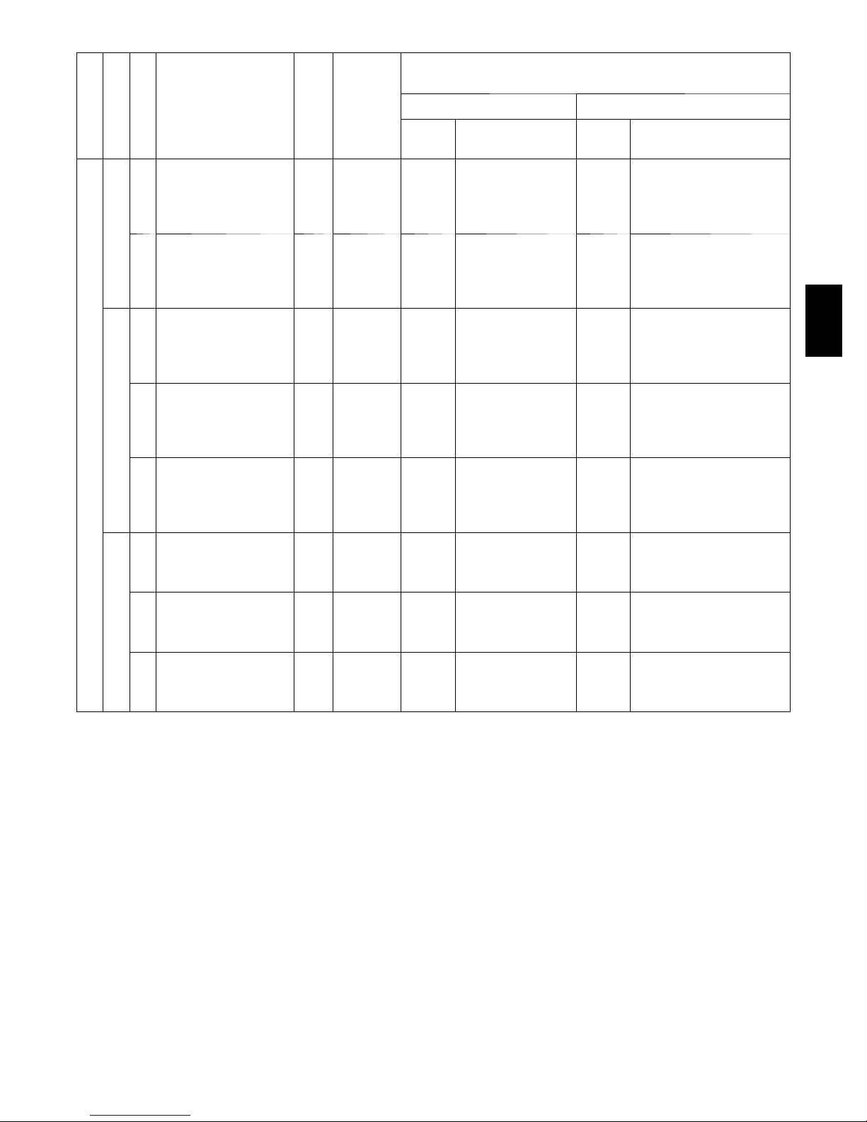
Table 8 – ELECTRIC HEAT -- ELECTRICAL DATA 3 -- 12. 5 TONS
SINGLE POINT KIT PART NUMBER
CRSINGLEXXXXXX
NO P.E.
w/P.E.
(pwrd fr/unit)
UNIT
50TC*A04
N O M . V --- P H --- H Z
208/230--- 1 --- 60
208/230--- 3 --- 60
4 6 0 --- 3 --- 6 0
ELECTRIC HEATER
PAR T NUMBE R
CRHEATERXXXXXX
IFM TYPE
101A00 4.4 3.3/4.0 --- --- --- --102A00 6.5 4.9/6.0 --- --- --- ---
STD
MED
STD
MED
HIGH
STD
MED
HIGH
103B00 8.7 6.5/8.0 --- --- --- --104B00 10.5 7.9/9.6 040A00 040A00 040A00 040A00
102A00,102A00 13 9.8/11.9 040A00 040A00 040A00 040A00
101A00 4.4 3.3/4.0 --- --- --- --102A00 6.5 4.9/6.0 --- --- --- --103B00 8.7 6.5/8.0 --- --- --- --104B00 10.5 7.9/9.6 040A00 040A00 040A00 040A00
102A00,102A00 13 9.8/11.9 040A00 040A00 040A00 040A00
101A00 4.4 3.3/4.0 --- --- --- --102A00 6.5 4.9/6.0 --- --- --- --103B00 8.7 6.5/8.0 --- --- --- --104B00 10.5 7.9/9.6 --- --- --- --105A00 16 12.0/14.7 --- --- 038A00 038A00
101A00 4.4 3.3/4.0 --- --- --- --102A00 6.5 4.9/6.0 --- --- --- --103B00 8.7 6.5/8.0 --- --- --- --104B00 10.5 7.9/9.6 --- --- --- --105A00 16 12.0/14.7 --- --- 038A00 038A00
101A00 4.4 3.3/4.0 --- --- --- --102A00 6.5 4.9/6.0 --- --- --- --103B00 8.7 6.5/8.0 --- --- --- --104B00 10.5 7.9/9.6 --- --- --- --105A00 16 12.0/14.7 --- --- 038A00 038A00
106A00 6 5.5 --- --- --- --107A00 8.8 8.1 --- --- --- --108A00 11.5 10.6 --- --- --- --109A00 14 12.9 --- --- --- --106A00 6 5.5 --- --- --- --107A00 8.8 8.1 --- --- --- --108A00 11.5 10.6 --- --- --- --109A00 14 12.9 --- --- --- --106A00 6 5.5 --- --- --- --107A00 8.8 8.1 --- --- --- --108A00 11.5 10.6 --- --- --- --109A00 14 12.9 --- --- --- ---
NOM
PWR
(kW)
APP
PWR
(kW)
NO C.O. or UNPWRD C.O. w/PWRD C.O.
NO P.E.
w/P.E.
(pwrd fr/unit)
50TC
LEGEND
APP PWR --- 208 / 230V / 460V / 575V
C.O. --- Convenient outlet
FLA --- Full load amps
IFM --- Indoor fan motor
NOM PWR -- - 240V / 480V / 600V
P.E . --- P ow e r e x h a u s t
PWRD --- Powered convenient outlet
UNPWRD -- - Unpowered convenient outlet
13

Table 8 -- (cont.) ELECTRIC HEAT -- ELECTRICAL DATA 3 -- 12. 5 TONS
SINGLE POINT KIT PART NUMBER
CRSINGLEXXXXXX
NO P.E.
w/P.E.
(pwrd fr/unit)
50TC
UNIT
50TC*A05
N O M . V --- P H --- H Z
208/230--- 1 --- 60
208/230--- 3 --- 60
4 6 0 --- 3 --- 6 0
ELECTRIC HEATER
PAR T NUMBE R
CRHEATERXXXXXX
IFM TYPE
101A00 4.4 3.3/4.0 --- --- --- --103B00 8.7 6.5/8.0 --- --- --- ---
102A00,102A00 13 9.8/11.9 040A00 040A00 040A00 040A00
STD
103B00,103B00 17.4 13.1/16.0 040A00 040A00 040A00 040A00
104B00,104B00 21 15.8/19.3 040A00 040A00 040A00 040A00
101A00 4.4 3.3/4.0 --- --- --- --103B00 8.7 6.5/8.0 --- --- --- ---
102A00,102A00 13 9.8/11.9 040A00 040A00 040A00 040A00
MED
103B00,103B00 17.4 13.1/16.0 040A00 040A00 040A00 040A00
104B00,104B00 21 15.8/19.3 040A00 040A00 040A00 040A00
102A00 6.5 4.9/6.0 --- --- --- --103B00 8.7 6.5/8.0 --- --- --- ---
STD
MED
HIGH
STD
MED
HIGH
105A00 16 12.0/14.7 --- --- 038A00 038A00
104B00,104B00 21 15.8/19.3 038A00 038A00 038A00 038A00
102A00 6.5 4.9/6.0 --- --- --- --103B00 8.7 6.5/8.0 --- --- --- --105A00 16 12.0/14.7 --- --- 038A00 038A00
104B00,104B00 21 15.8/19.3 038A00 038A00 038A00 038A00
102A00 6.5 4.9/6.0 --- --- --- --103B00 8.7 6.5/8.0 --- --- --- --105A00 16 12.0/14.7 --- --- 038A00 038A00
104B00,104B00 21 15.8/19.3 038A00 038A00 038A00 038A00
106A00 6 5.5 --- --- --- --108A00 11.5 10.6 --- --- --- --109A00 14 12.9 --- --- --- ---
108A00,108A00 23 21.1 --- --- --- ---
106A00 6 5.5 --- --- --- --108A00 11.5 10.6 --- --- --- --109A00 14 12.9 --- --- --- ---
108A00,108A00 23 21.1 --- --- --- ---
106A00 6 5.5 --- --- --- --108A00 11.5 10.6 --- --- --- --109A00 14 12.9 --- --- --- ---
108A00,108A00 23 21.1 --- --- --- ---
NOM
PWR
(kW)
APP
PWR
(kW)
NO C.O. or UNPWRD C.O. w/PWRD C.O.
NO P.E.
w/P.E.
(pwrd fr/unit)
LEGEND
APP PWR --- 208 / 230V / 460V / 575V
C.O. --- Convenient outlet
FLA --- Full load amps
IFM --- Indoor fan motor
NOM PWR -- - 240V / 480V / 600V
P.E . --- P ow e r e x h a u s t
PWRD --- Powered convenient outlet
UNPWRD -- - Unpowered convenient outlet
14

Table 8 -- (cont.) ELECTRIC HEAT -- ELECTRICAL DATA 3 -- 12. 5 TONS
SINGLE POINT KIT PART NUMBER
CRSINGLEXXXXXX
NO P.E.
w/P.E.
(pwrd fr/unit)
UNIT
50TC*A06
N O M . V --- P H --- H Z
208/230--- 1 --- 60
208/230--- 3 --- 60
4 6 0 --- 3 --- 6 0
ELECTRIC HEATER
PAR T NUMBE R
CRHEATERXXXXXX
IFM TYPE
102A00 6.5 4.9/6.0 --- --- --- --103B00 8.7 6.5/8.0 --- --- --- ---
102A00,102A00 13 9.8/11.9 040A00 040A00 040A00 040A00
STD
103B00,103B00 17.4 13.1/16.0 040A00 040A00 040A00 040A00
104B00,104B00 21 15.8/19.3 040A00 040A00 040A00 040A00
102A00 6.5 4.9/6.0 --- --- --- --103B00 8.7 6.5/8.0 --- --- 040A00 040A00
102A00,102A00 13 9.8/11.9 040A00 040A00 040A00 040A00
MED
103B00,103B00 17.4 13.1/16.0 040A00 040A00 040A00 040A00
104B00,104B00 21 15.8/19.3 040A00 040A00 040A00 040A00
102A00 6.5 4.9/6.0 --- --- --- --104B00 10.5 7.9/9.6 --- --- --- ---
STD
MED
HIGH
STD
MED
HIGH
105A00 16 12.0/14.7 --- --- 038A00 038A00
104B00,104B00 21 15.8/19.3 038A00 038A00 038A00 038A00
104B00,105A00 26.5 19.9/24.3 038A00 038A00 038A00 038A00
102A00 6.5 4.9/6.0 --- --- --- ---
104B00 10.5 7.9/9.6 --- --- --- ---
105A00 16 12.0/14.7 --- --- 038A00 038A00
104B00,104B00 21 15.8/19.3 038A00 038A00 038A00 038A00
104B00,105A00 26.5 19.9/24.3 038A00 038A00 038A00 038A00
102A00 6.5 4.9/6.0 --- --- --- ---
104B00 10.5 7.9/9.6 --- --- --- ---
105A00 16 12.0/14.7 --- --- 038A00 038A00
104B00,104B00 21 15.8/19.3 038A00 038A00 038A00 038A00
104B00,105A00 26.5 19.9/24.3 038A00 038A00 038A00 038A00
106A00 6 5.5 --- --- --- ---
108A00 11.5 10.6 --- --- --- ---
109A00 14 12.9 --- --- --- --108A00,108A00 23 21.1 --- --- --- --108A00,109A00 25.5 23.4 --- --- --- ---
106A00 6 5.5 --- --- --- ---
108A00 11.5 10.6 --- --- --- ---
109A00 14 12.9 --- --- --- --108A00,108A00 23 21.1 --- --- --- --108A00,109A00 25.5 23.4 --- --- --- ---
106A00 6 5.5 --- --- --- ---
108A00 11.5 10.6 --- --- --- ---
109A00 14 12.9 --- --- --- --108A00,108A00 23 21.1 --- --- --- --108A00,109A00 25.5 23.4 --- --- --- ---
NOM
PWR
(kW)
APP
PWR
(kW)
NO C.O. or UNPWRD C.O. w/PWRD C.O.
NO P.E.
w/P.E.
(pwrd fr/unit)
50TC
LEGEND
APP PWR --- 208 / 230V / 460V / 575V
C.O. --- Convenient outlet
FLA --- Full load amps
IFM --- Indoor fan motor
NOM PWR -- - 240V / 480V / 600V
P.E . --- P ow e r e x h a u s t
PWRD --- Powered convenient outlet
UNPWRD -- - Unpowered convenient outlet
15

Table 8 -- (cont.) ELECTRIC HEAT -- ELECTRICAL DATA 3 -- 12. 5 TONS
SINGLE POINT KIT PART NUMBER
CRSINGLEXXXXXX
NO P.E.
w/P.E.
(pwrd fr/unit)
50TC
UNIT
50TC*A07
N O M . V --- P H --- H Z
208/230--- 3 --- 60
4 6 0 --- 3 --- 6 0
ELECTRIC HEATER
PAR T NUMBE R
CRHEATERXXXXXX
IFM TYPE
102A00 6.5 4.9/6.0 --- --- --- --104B00 10.5 7.9/9.6 --- --- --- ---
STD
MED
HIGH
STD
MED
HIGH
105A00 16.0 12.0/14.7 037A00 037A00 038A00 038A00
104B00,104B00 21.0 15.8/19.3 038A00 038A00 038A00 038A00
104B00,105A00 26.5 19.9/24.3 038A00 038A00 038A00 038A00
102A00 6.5 4.9/6.0 --- --- --- ---
104B00 10.5 7.9/9.6 --- --- --- ---
105A00 16.0 12.0/14.7 037A00 037A00 038A00 038A00
104B00,104B00 21.0 15.8/19.3 038A00 038A00 038A00 038A00
104B00,105A00 26.5 19.9/24.3 038A00 038A00 038A00 038A00
102A00 6.5 4.9/6.0 --- --- --- ---
104B00 10.5 7.9/9.6 --- --- --- ---
105A00 16.0 12.0/14.7 037A00 037A00 038A00 038A00
104B00,104B00 21.0 15.8/19.3 038A00 038A00 038A00 038A00
104B00,105A00 26.5 19.9/24.3 038A00 038A00 038A00 038A00
106A00 6.0 5.5 --- --- --- ---
108A00 11.5 10.6 --- --- --- ---
109A00 14.0 12.9 --- --- --- --108A00,108A00 23.0 21.1 037A00 037A00 037A00 037A00
108A00,109A00 25.5 23.4 037A00 037A00 037A00 037A00
106A00 6.0 5.5 --- --- --- ---
108A00 11.5 10.6 --- --- --- ---
109A00 14.0 12.9 --- --- --- --108A00,108A00 23.0 21.1 037A00 037A00 037A00 037A00
108A00,109A00 25.5 23.4 037A00 037A00 037A00 037A00
106A00 6.0 5.5 --- --- --- ---
108A00 11.5 10.6 --- --- --- ---
109A00 14.0 12.9 --- --- --- --108A00,108A00 23.0 21.1 037A00 037A00 037A00 037A00
108A00,109A00 25.5 23.4 037A00 037A00 037A00 037A00
NOM
PWR
(kW)
APP
PWR
(kW)
NO C.O. or UNPWRD C.O. w/PWRD C.O.
NO P.E.
w/P.E.
(pwrd fr/unit)
LEGEND
APP PWR --- 208 / 230V / 460V / 575V
C.O. --- Convenient outlet
FLA --- Full load amps
IFM --- Indoor fan motor
NOM PWR -- - 240V / 480V / 600V
P.E . --- P ow e r e x h a u s t
PWRD --- Powered convenient outlet
UNPWRD -- - Unpowered convenient outlet
16

Table 8 -- (cont.) ELECTRIC HEAT -- ELECTRICAL DATA 3 -- 12. 5 TONS
SINGLE POINT KIT PART NUMBER
CRSINGLEXXXXXX
NO P.E.
w/P.E.
(pwrd fr/unit)
UNIT
50TC*A08
N O M . V --- P H --- H Z
208/230--- 3 --- 60
4 6 0 --- 3 --- 6 0
5 7 5 --- 3 --- 6 0
ELECTRIC HEATER
PAR T NUMBE R
CRHEATERXXXXXX
IFM TYPE
117A00 10.4 7.8/9.6 042A00 042A00 042A00 042A00
110A00 16.0 12.0/14.7 042A00 042A00 043A00 043A00
STD
MED
HIGH
STD
MED
HIGH
STD
MED
HIGH
111A00 24.8 18.6/22.8 043A00 043A00 043A00 043A00
112A00 32.0 24.0/29.4 043A00 043A00 043A00 043A00
112A00,117A00 42.4 31.8/38.9 045A00 045A00 045A00 045A00
117A00 10.4 7.8/9.6 042A00 042A00 042A00 042A00
110A00 16.0 12.0/14.7 042A00 043A00 043A00 043A00
111A00 24.8 18.6/22.8 043A00 043A00 043A00 043A00
112A00 32.0 24.0/29.4 043A00 043A00 043A00 043A00
112A00,117A00 42.4 31.8/38.9 045A00 045A00 045A00 045A00
117A00 10.4 7.8/9.6 042A00 042A00 043A00 043A00
110A00 16.0 12.0/14.7 043A00 043A00 043A00 043A00
111A00 24.8 18.6/22.8 043A00 043A00 043A00 043A00
112A00 32.0 24.0/29.4 043A00 043A00 043A00 043A00
112A00,117A00 42.4 31.8/38.9 045A00 045A00 045A00 045A00
116A00 13.9 12.8 042A00 042A00 042A00 042A00
113A00 16.5 15.2 042A00 042A00 042A00 042A00
114A00 27.8 25.5 042A00 042A00 042A00 042A00
115A00 33.0 30.3 042A00 042A00 042A00 042A00
114A00,116A00 41.7 38.3 044A00 044A00 044A00 044A00
116A00 13.9 12.8 042A00 042A00 042A00 042A00
113A00 16.5 15.2 042A00 042A00 042A00 042A00
114A00 27.8 25.5 042A00 042A00 042A00 042A00
115A00 33.0 30.3 042A00 042A00 042A00 042A00
114A00,116A00 41.7 38.3 044A00 044A00 044A00 044A00
116A00 13.9 12.8 042A00 042A00 042A00 042A00
113A00 16.5 15.2 042A00 042A00 042A00 042A00
114A00 27.8 25.5 042A00 042A00 042A00 042A00
115A00 33.0 30.3 042A00 044A00 044A00 044A00
114A00,116A00 41.7 38.3 044A00 044A00 044A00 044A00
118A00 17.0 17.0 042A00 042A00 042A00 042A00
119A00 34.0 34.0 042A00 042A00 042A00 044A00
118A00 17.0 17.0 042A00 042A00 042A00 042A00
119A00 34.0 34.0 042A00 042A00 042A00 044A00
118A00 17.0 17.0 042A00 042A00 042A00 042A00
119A00 34.0 34.0 042A00 044A00 044A00 044A00
NOM
PWR
(kW)
APP
PWR
(kW)
NO C.O. or UNPWRD C.O. w/PWRD C.O.
NO P.E.
w/P.E.
(pwrd fr/unit)
50TC
LEGEND
APP PWR --- 208 / 230V / 460V / 575V
C.O. --- Convenient outlet
FLA --- Full load amps
IFM --- Indoor fan motor
NOM PWR -- - 240V / 480V / 600V
P.E . --- P ow e r e x h a u s t
PWRD --- Powered convenient outlet
UNPWRD -- - Unpowered convenient outlet
17
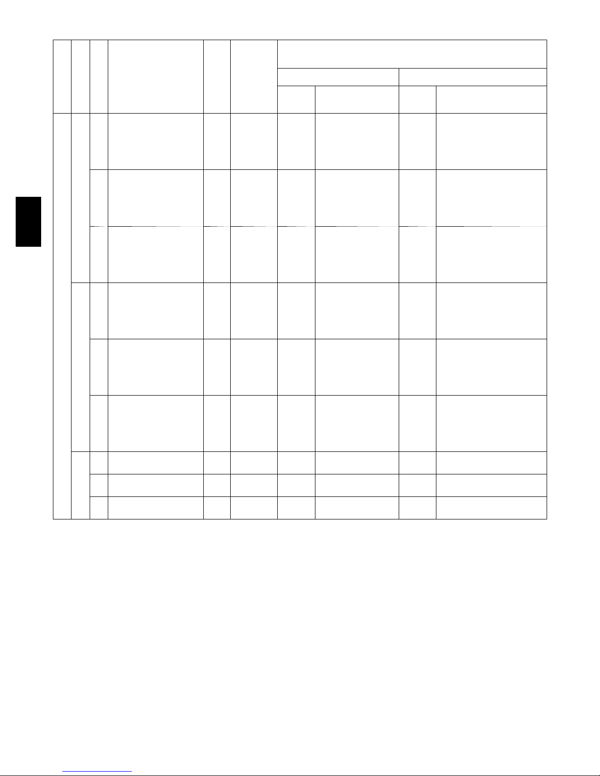
Table 8 -- (cont.) ELECTRIC HEAT -- ELECTRICAL DATA 3 -- 12. 5 TONS
SINGLE POINT KIT PART NUMBER
CRSINGLEXXXXXX
NO P.E.
w/P.E.
(pwrd fr/unit)
50TC
ELECTRIC HEATER
UNIT
N O M . V --- P H --- H Z
208/230--- 3 --- 60
50TC*D08
4 6 0 --- 3 --- 6 0
5 7 5 --- 3 --- 6 0
PAR T NUMBE R
CRHEATERXXXXXX
IFM TYPE
117A00 10.4 7.8/9.6 042A00 042A00 042A00 042A00
110A00 16.0 12.0/14.7 042A00 042A00 043A00 043A00
STD
MED
HIGH
STD
MED
HIGH
STD
MED
HIGH
111A00 24.8 18.6/22.8 043A00 043A00 043A00 043A00
112A00 32.0 24.0/29.4 043A00 043A00 043A00 043A00
112A00,117A00 42.4 31.8/38.9 045A00 045A00 045A00 045A00
117A00 10.4 7.8/9.6 042A00 042A00 042A00 042A00
110A00 16.0 12.0/14.7 042A00 043A00 043A00 043A00
111A00 24.8 18.6/22.8 043A00 043A00 043A00 043A00
112A00 32.0 24.0/29.4 043A00 043A00 043A00 043A00
112A00,117A00 42.4 31.8/38.9 045A00 045A00 045A00 045A00
117A00 10.4 7.8/9.6 042A00 042A00 042A00 043A00
110A00 16.0 12.0/14.7 043A00 043A00 043A00 043A00
111A00 24.8 18.6/22.8 043A00 043A00 043A00 043A00
112A00 32.0 24.0/29.4 043A00 043A00 043A00 043A00
112A00,117A00 42.4 31.8/38.9 045A00 045A00 045A00 045A00
116A00 13.9 12.8 042A00 042A00 042A00 042A00
113A00 16.5 15.2 042A00 042A00 042A00 042A00
114A00 27.8 25.5 042A00 042A00 042A00 042A00
115A00 33.0 30.3 042A00 042A00 042A00 042A00
114A00,116A00 41.7 38.3 044A00 044A00 044A00 044A00
116A00 13.9 12.8 042A00 042A00 042A00 042A00
113A00 16.5 15.2 042A00 042A00 042A00 042A00
114A00 27.8 25.5 042A00 042A00 042A00 042A00
115A00 33.0 30.3 042A00 042A00 042A00 042A00
114A00,116A00 41.7 38.3 044A00 044A00 044A00 044A00
116A00 13.9 12.8 042A00 042A00 042A00 042A00
113A00 16.5 15.2 042A00 042A00 042A00 042A00
114A00 27.8 25.5 042A00 042A00 042A00 042A00
115A00 33.0 30.3 042A00 044A00 044A00 044A00
114A00,116A00 41.7 38.3 044A00 044A00 044A00 044A00
118A00 17.0 17.0 042A00 042A00 042A00 042A00
119A00 34.0 34.0 042A00 042A00 042A00 044A00
118A00 17.0 17.0 042A00 042A00 042A00 042A00
119A00 34.0 34.0 042A00 042A00 042A00 044A00
118A00 17.0 17.0 042A00 042A00 042A00 042A00
119A00 34.0 34.0 042A00 044A00 044A00 044A00
NOM
PWR
(kW)
APP
PWR
(kW)
NO C.O. or UNPWRD C.O. w/PWRD C.O.
NO P.E.
w/P.E.
(pwrd fr/unit)
LEGEND
APP PWR --- 208 / 230V / 460V / 575V
C.O. --- Convenient outlet
FLA --- Full load amps
IFM --- Indoor fan motor
NOM PWR -- - 240V / 480V / 600V
P.E . --- P ow e r e x h a u s t
PWRD --- Powered convenient outlet
UNPWRD -- - Unpowered convenient outlet
18
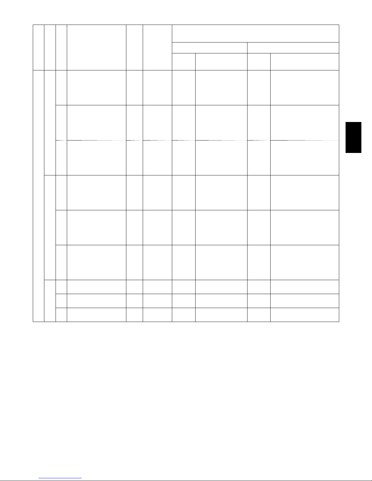
Table 8 -- (cont.) ELECTRIC HEAT -- ELECTRICAL DATA 3 -- 12. 5 TONS
SINGLE POINT KIT PART NUMBER
CRSINGLEXXXXXX
NO P.E.
w/P.E.
(pwrd fr/unit)
UNIT
50TC*A09
N O M . V --- P H --- H Z
208/230--- 3 --- 60
4 6 0 --- 3 --- 6 0
5 7 5 --- 3 --- 6 0
ELECTRIC HEATER
PAR T NUMBE R
CRHEATERXXXXXX
IFM TYPE
117A00 10.4 7.8/9.6 047A00 047A00 047A00 049A00
110A00 16.0 12.0/14.7 047A00 047A00 049A00 049A00
STD
MED
HIGH
STD
MED
HIGH
STD
MED
HIGH
111A00 24.8 18.6/22.8 049A00 049A00 049A00 049A00
112A00 32.0 24.0/29.4 049A00 049A00 049A00 049A00
112A00,117A00 42.4 31.8/38.9 051A00 051A00 051A00 051A00
117A00 10.4 7.8/9.6 047A00 047A00 047A00 049A00
110A00 16.0 12.0/14.7 047A00 047A00 049A00 049A00
111A00 24.8 18.6/22.8 049A00 049A00 049A00 049A00
112A00 32.0 24.0/29.4 049A00 049A00 049A00 049A00
112A00,117A00 42.4 31.8/38.9 051A00 051A00 051A00 051A00
117A00 10.4 7.8/9.6 047A00 049A00 049A00 049A00
110A00 16.0 12.0/14.7 049A00 049A00 049A00 049A00
111A00 24.8 18.6/22.8 049A00 049A00 049A00 049A00
112A00 32.0 24.0/29.4 049A00 049A00 049A00 049A00
112A00,117A00 42.4 31.8/38.9 051A00 051A00 051A00 051A00
116A00 13.9 12.8 047A00 047A00 047A00 047A00
113A00 16.5 15.2 047A00 047A00 047A00 047A00
114A00 27.8 25.5 047A00 047A00 047A00 047A00
115A00 33.0 30.3 047A00 047A00 047A00 047A00
114A00,116A00 41.7 38.3 050A00 050A00 050A00 050A00
116A00 13.9 12.8 047A00 047A00 047A00 047A00
113A00 16.5 15.2 047A00 047A00 047A00 047A00
114A00 27.8 25.5 047A00 047A00 047A00 047A00
115A00 33.0 30.3 047A00 047A00 047A00 047A00
114A00,116A00 41.7 38.3 050A00 050A00 050A00 050A00
116A00 13.9 12.8 047A00 047A00 047A00 047A00
113A00 16.5 15.2 047A00 047A00 047A00 047A00
114A00 27.8 25.5 047A00 047A00 047A00 047A00
115A00 33.0 30.3 047A00 047A00 047A00 050A00
114A00,116A00 41.7 38.3 050A00 050A00 050A00 050A00
118A00 17.0 17.0 047A00 047A00 047A00 047A00
119A00 34.0 34.0 047A00 047A00 047A00 050A00
118A00 17.0 17.0 047A00 047A00 047A00 047A00
119A00 34.0 34.0 047A00 047A00 047A00 050A00
118A00 17.0 17.0 047A00 047A00 047A00 047A00
119A00 34.0 34.0 047A00 047A00 047A00 050A00
NOM
PWR
(kW)
APP
PWR
(kW)
NO C.O. or UNPWRD C.O. w/PWRD C.O.
NO P.E.
w/P.E.
(pwrd fr/unit)
50TC
LEGEND
APP PWR --- 208 / 230V / 460V / 575V
C.O. --- Convenient outlet
FLA --- Full load amps
IFM --- Indoor fan motor
NOM PWR -- - 240V / 480V / 600V
P.E . --- P ow e r e x h a u s t
PWRD --- Powered convenient outlet
UNPWRD -- - Unpowered convenient outlet
19

Table 8 -- (cont.) ELECTRIC HEAT -- ELECTRICAL DATA 3 -- 12. 5 TONS
SINGLE POINT KIT PART NUMBER
CRSINGLEXXXXXX
NO P.E.
w/P.E.
(pwrd fr/unit)
50TC
UNIT
50TC*A12
N O M . V --- P H --- H Z
208/230--- 3 --- 60
4 6 0 --- 3 --- 6 0
5 7 5 --- 3 --- 6 0
ELECTRIC HEATER
PAR T NUMBE R
CRHEATERXXXXXX
IFM TYPE
117A00 10.4 7.8/9.6 047A00 047A00 047A00 049A00
110A00 16.0 12.0/14.7 047A00 047A00 049A00 049A00
STD
MED
HIGH
STD
MED
HIGH
STD
MED
HIGH
112A00 32.0 24.0/29.4 049A00 049A00 049A00 049A00
112A00,117A00 42.4 31.8/38.9 051A00 051A00 051A00 051A00
112A00,110A00 50.0 37.6/45.9 051A00 051A00 051A00 051A00
117A00 10.4 7.8/9.6 047A00 049A00 049A00 049A00
110A00 16.0 12.0/14.7 049A00 049A00 049A00 049A00
112A00 32.0 24.0/29.4 049A00 049A00 049A00 049A00
112A00,117A00 42.4 31.8/38.9 051A00 051A00 051A00 051A00
112A00,110A00 50.0 37.6/45.9 051A00 051A00 051A00 051A00
117A00 10.4 7.8/9.6 049A00 049A00 049A00 049A00
110A00 16.0 12.0/14.7 049A00 049A00 049A00 049A00
112A00 32.0 24.0/29.4 049A00 049A00 049A00 049A00
112A00,117A00 42.4 31.8/38.9 051A00 051A00 051A00 051A00
112A00,110A00 50.0 37.6/45.9 051A00 051A00 051A00 051A00
116A00 13.9 12.8 047A00 047A00 047A00 047A00
113A00 16.5 15.2 047A00 047A00 047A00 047A00
115A00 33.0 30.3 047A00 047A00 047A00 047A00
114A00,116A00 41.7 38.3 050A00 050A00 050A00 050A00
115A00,113A00 50.0 45.9 050A00 050A00 050A00 050A00
116A00 13.9 12.8 047A00 047A00 047A00 047A00
113A00 16.5 15.2 047A00 047A00 047A00 047A00
115A00 33.0 30.3 047A00 047A00 047A00 050A00
114A00,116A00 41.7 38.3 050A00 050A00 050A00 050A00
115A00,113A00 50.0 45.9 050A00 050A00 050A00 050A00
116A00 13.9 12.8 047A00 047A00 047A00 047A00
113A00 16.5 15.2 047A00 047A00 047A00 047A00
115A00 33.0 30.3 047A00 050A00 050A00 050A00
114A00,116A00 41.7 38.3 050A00 050A00 050A00 050A00
115A00,113A00 50.0 45.9 050A00 050A00 050A00 050A00
118A00 17.0 17.0 047A00 047A00 047A00 047A00
119A00 34.0 34.0 047A00 047A00 047A00 050A00
118A00,119A00 51.0 51.0 050A00 050A00 050A00 050A00
118A00 17.0 17.0 047A00 047A00 047A00 047A00
119A00 34.0 34.0 047A00 047A00 047A00 050A00
118A00,119A00 51.0 51.0 050A00 050A00 050A00 050A00
118A00 17.0 17.0 047A00 047A00 047A00 047A00
119A00 34.0 34.0 047A00 050A00 050A00 050A00
118A00,119A00 51.0 51.0 050A00 050A00 050A00 050A00
NOM
PWR
(kW)
APP
PWR
(kW)
NO C.O. or UNPWRD C.O. w/PWRD C.O.
NO P.E.
w/P.E.
(pwrd fr/unit)
LEGEND
APP PWR --- 208 / 230V / 460V / 575V
C.O. --- Convenient outlet
FLA --- Full load amps
IFM --- Indoor fan motor
NOM PWR -- - 240V / 480V / 600V
P.E . --- P ow e r e x h a u s t
PWRD --- Powered convenient outlet
UNPWRD -- - Unpowered convenient outlet
20

Table 8 -- (cont.) ELECTRIC HEAT -- ELECTRICAL DATA 3 -- 12.5 TONS
SINGLE POINT KIT PART NUMBER
ELECTRIC HEATER
UNIT
N O M . V --- P H --- H Z
208/230--- 3 --- 60
50TC*D12
4 6 0 --- 3 --- 6 0
5 7 5 --- 3 --- 6 0
PAR T NUMBE R
CRHEATERXXXXXX
IFM TYPE
117A00 10.4 7.8/9.6 047A00 047A00 047A00 047A00
110A00 16.0 12.0/14.7 047A00 047A00 049A00 049A00
STD
MED
HIGH
STD
MED
HIGH
STD
MED
HIGH
112A00 32.0 24.0/29.4 049A00 049A00 049A00 049A00
112A00,117A00 42.4 31.8/38.9 051A00 051A00 051A00 051A00
112A00,110A00 50.0 37.6/45.9 051A00 051A00 051A00 051A00
117A00 10.4 7.8/9.6 047A00 047A00 047A00 049A00
110A00 16.0 12.0/14.7 049A00 049A00 049A00 049A00
112A00 32.0 24.0/29.4 049A00 049A00 049A00 049A00
112A00,117A00 42.4 31.8/38.9 051A00 051A00 051A00 051A00
112A00,110A00 50.0 37.6/45.9 051A00 051A00 051A00 051A00
117A00 10.4 7.8/9.6 047A00 049A00 049A00 049A00
110A00 16.0 12.0/14.7 049A00 049A00 049A00 049A00
112A00 32.0 24.0/29.4 049A00 049A00 049A00 049A00
112A00,117A00 42.4 31.8/38.9 051A00 051A00 051A00 051A00
112A00,110A00 50.0 37.6/45.9 051A00 051A00 051A00 051A00
116A00 13.9 12.8 047A00 047A00 047A00 047A00
113A00 16.5 15.2 047A00 047A00 047A00 047A00
115A00 33.0 30.3 047A00 047A00 047A00 047A00
114A00,116A00 41.7 38.3 050A00 050A00 050A00 050A00
115A00,113A00 50.0 45.9 050A00 050A00 050A00 050A00
116A00 13.9 12.8 047A00 047A00 047A00 047A00
113A00 16.5 15.2 047A00 047A00 047A00 047A00
115A00 33.0 30.3 047A00 047A00 047A00 050A00
114A00,116A00 41.7 38.3 050A00 050A00 050A00 050A00
115A00,113A00 50.0 45.9 050A00 050A00 050A00 050A00
116A00 13.9 12.8 047A00 047A00 047A00 047A00
113A00 16.5 15.2 047A00 047A00 047A00 047A00
115A00 33.0 30.3 047A00 050A00 050A00 050A00
114A00,116A00 41.7 38.3 050A00 050A00 050A00 050A00
115A00,113A00 50.0 45.9 050A00 050A00 050A00 050A00
118A00 17.0 17.0 047A00 047A00 047A00 047A00
119A00 34.0 34.0 047A00 047A00 047A00 050A00
118A00,119A00 51.0 51.0 050A00 050A00 050A00 050A00
118A00 17.0 17.0 047A00 047A00 047A00 047A00
119A00 34.0 34.0 047A00 047A00 047A00 050A00
118A00,119A00 51.0 51.0 050A00 050A00 050A00 050A00
118A00 17.0 17.0 047A00 047A00 047A00 047A00
119A00 34.0 34.0 047A00 050A00 050A00 050A00
118A00,119A00 51.0 51.0 050A00 050A00 050A00 050A00
NOM
PWR
(kW)
APP
PWR
(kW)
NO C.O. or UNPWRD C.O. w/PWRD C.O.
NO P.E.
w/P.E.
(pwrd fr/unit)
CRSINGLEXXXXXX
NO P.E.
(pwrd fr/unit)
w/P.E.
50TC
LEGEND
APP PWR --- 208 / 230V / 460V / 575V
C.O. --- Convenient outlet
FLA --- Full load amps
IFM --- Indoor fan motor
NOM PWR -- - 240V / 480V / 600V
P.E . --- P ow e r e x h a u s t
PWRD --- Powered convenient outlet
UNPWRD -- - Unpowered convenient outlet
21

Table 8 -- (cont.) ELECTRIC HEAT -- ELECTRICAL DATA 3 -- 12.5 TONS
SINGLE POINT KIT PART NUMBER
CRSINGLEXXXXXX
NO P.E.
50TC
ELECTRIC HEATER
UNIT
N O M . V --- P H --- H Z
208/230--- 3 --- 60
50TC*D14
4 6 0 --- 3 --- 6 0
5 7 5 --- 3 --- 6 0
PAR T NUMBE R
CRHEATERXXXXXX
IFM TYPE
117A00 10.4 7.8/9.6 049A00 049A00 049A00 049A00
110A00 16.0 12.0/14.7 049A00 049A00 049A00 049A00
STD
MED
HIGH
STD
MED
HIGH
STD
MED
HIGH
112A00 32.0 24.0/29.4 049A00 049A00 049A00 049A00
112A00,117A00 42.4 31.8/38.9 051A00 051A00 051A00 051A00
112A00,110A00 50.0 37.6/45.9 051A00 051A00 051A00 051A00
117A00 10.4 7.8/9.6 049A00 049A00 049A00 049A00
110A00 16.0 12.0/14.7 049A00 049A00 049A00 049A00
112A00 32.0 24.0/29.4 049A00 049A00 049A00 049A00
112A00,117A00 42.4 31.8/38.9 051A00 051A00 051A00 051A00
112A00,110A00 50.0 37.6/45.9 051A00 051A00 051A00 051A00
Std Unit Without Heat --- --- --- --- --- 049A00
117A00 10.4 7.8/9.6 049A00 049A00 049A00 049A00
110A00 16.0 12.0/14.7 049A00 049A00 049A00 049A00
112A00 32.0 24.0/29.4 049A00 049A00 049A00 049A00
112A00,117A00 42.4 31.8/38.9 051A00 051A00 051A00 051A00
112A00,110A00 50.0 37.6/45.9 051A00 051A00 051A00 051A00
116A00 13.9 12.8 047A00 047A00 047A00 047A00
113A00 16.5 15.2 047A00 047A00 047A00 047A00
115A00 33.0 30.3 047A00 047A00 047A00 047A00
114A00,116A00 41.7 38.3 050A00 050A00 050A00 050A00
115A00,113A00 50.0 45.9 050A00 050A00 050A00 050A00
116A00 13.9 12.8 047A00 047A00 047A00 047A00
113A00 16.5 15.2 047A00 047A00 047A00 047A00
115A00 33.0 30.3 047A00 047A00 047A00 050A00
114A00,116A00 41.7 38.3 050A00 050A00 050A00 050A00
115A00,113A00 50.0 45.9 050A00 050A00 050A00 050A00
116A00 13.9 12.8 047A00 047A00 047A00 047A00
113A00 16.5 15.2 047A00 047A00 047A00 047A00
115A00 33.0 30.3 047A00 050A00 050A00 050A00
114A00,116A00 41.7 38.3 050A00 050A00 050A00 050A00
115A00,113A00 50.0 45.9 050A00 050A00 050A00 050A00
118A00 17.0 17.0 047A00 047A00 047A00 047A00
119A00 34.0 34.0 047A00 047A00 047A00 050A00
118A00,119A00 51.0 51.0 050A00 050A00 050A00 050A00
118A00 17.0 17.0 047A00 047A00 047A00 047A00
119A00 34.0 34.0 047A00 047A00 047A00 050A00
118A00,119A00 51.0 51.0 050A00 050A00 050A00 050A00
118A00 17.0 17.0 047A00 047A00 047A00 047A00
119A00 34.0 34.0 047A00 050A00 050A00 050A00
118A00,119A00 51.0 51.0 050A00 050A00 050A00 050A00
NOM
PWR
(kW)
APP
PWR
(kW)
NO C.O. or UNPWRD C.O. w/PWRD C.O.
NO P.E.
w/P.E.
(pwrd fr/unit)
w/P.E.
(pwrd fr/unit)
LEGEND
APP PWR --- 208 / 230V / 460V / 575V
C.O. --- Convenient outlet
FLA --- Full load amps
IFM --- Indoor fan motor
NOM PWR -- - 240V / 480V / 600V
P.E . --- P ow e r e x h a u s t
PWRD --- Powered convenient outlet
UNPWRD -- - Unpowered convenient outlet
22

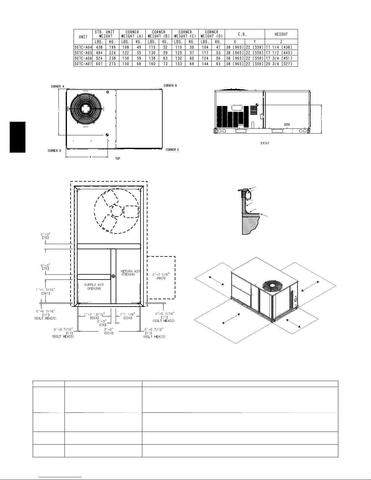
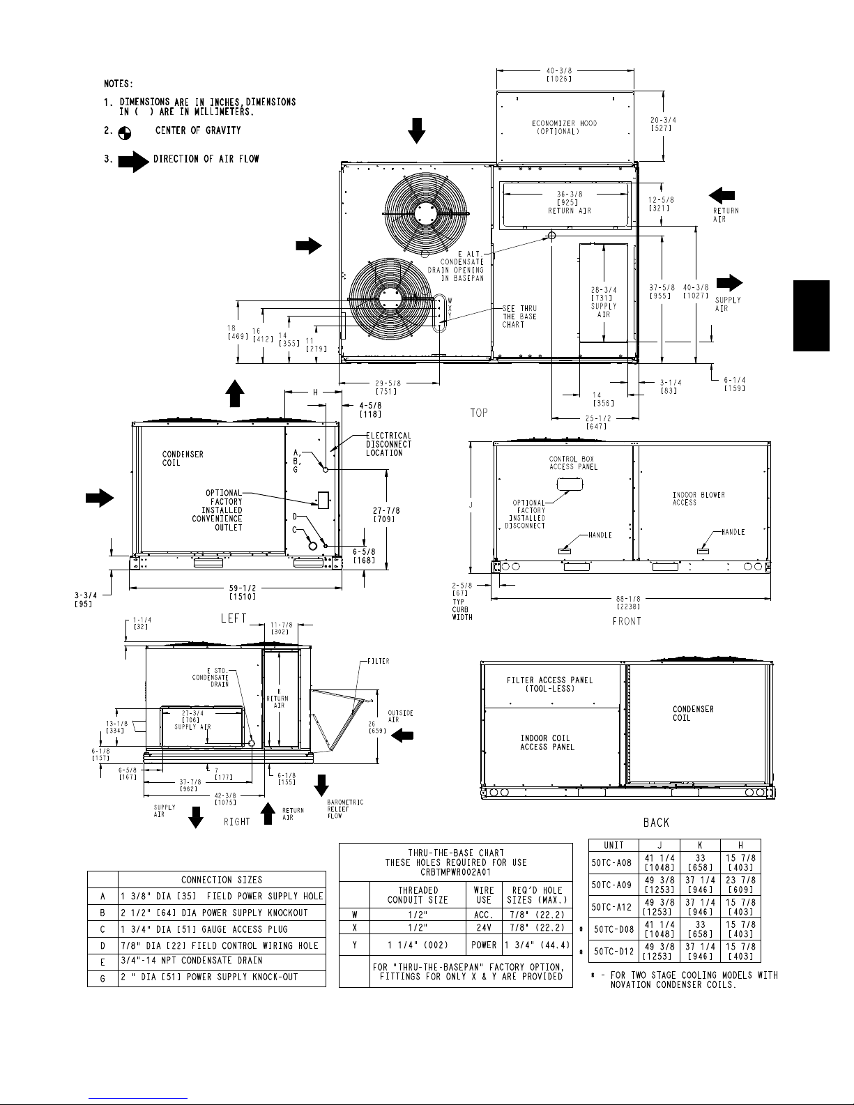
CURBS & WEIGHTS DIMENSIONS -- CHASSIS 1
50TC
C08529
Fig. 1 -- Dimensions 50TC 04-- 0 7
23
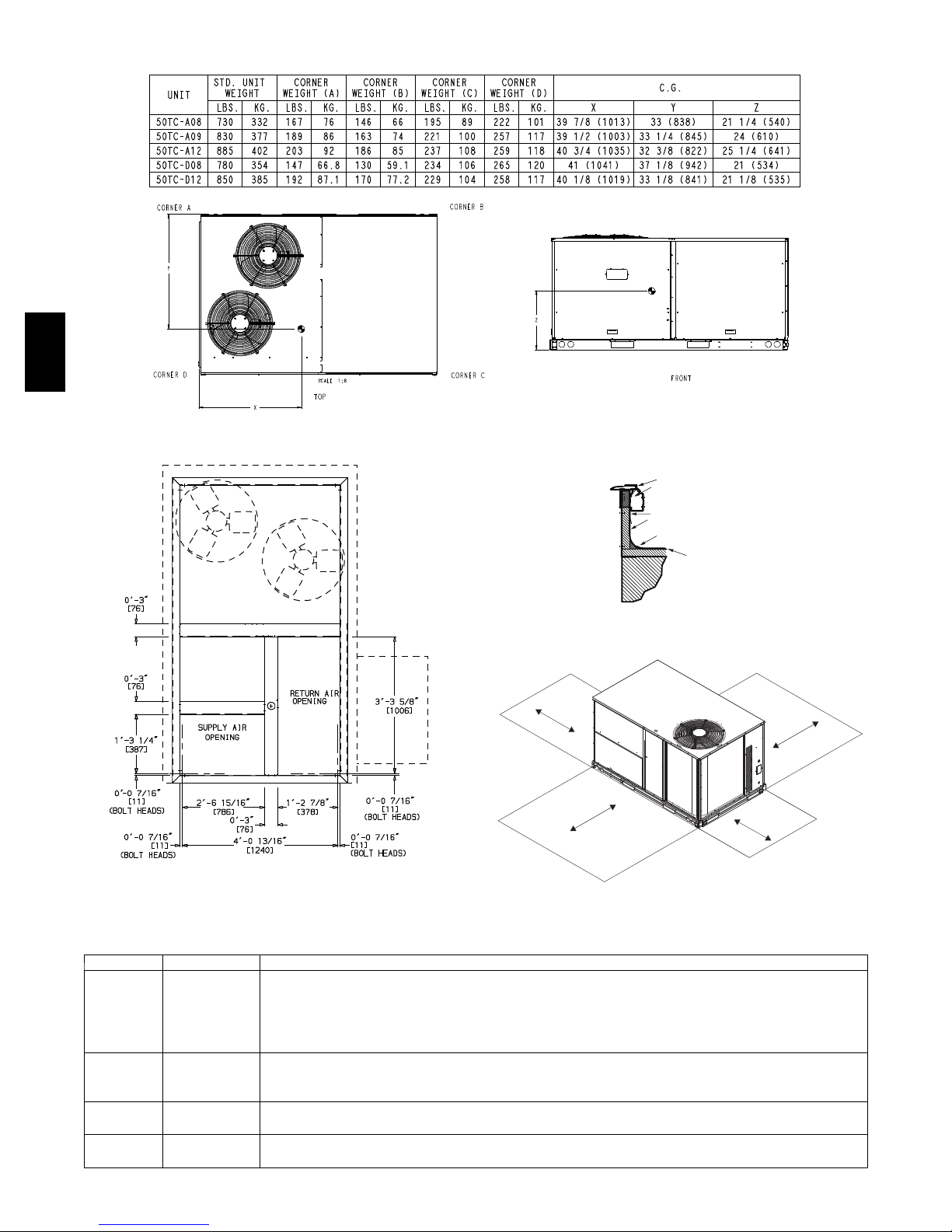
50TC
CURBS & WEIGHTS DIMENSIONS -- CHASSIS 1 (cont.)
Fig. 2 -- Dimensions 50TC 04-- 0 7
GASKET
(SUPPLIED WITH CURB)
NAIL
COUNTER FLASHING
(FIELD SUPPLIED)
ROOFING FELT
(FIELD SUPPLIED)
CANT STRIP
(FIELD SUPPLIED)
ROOFING FELT
(FIELD SUPPLIED)
C08530
C07458
Fig. 3 -- Curb Dimensions
LOC DIMENSION CONDITION
48” (1219 mm) Unit disconnect is mounted on panel
A
B
C
D
18” (457 mm) No disconnect, convenience outlet option
18” (457 mm) Recommended service clearance
12” (305 mm) Minimum clearance
42” (1067 mm) Surface behind servicer is grounded (e.g., metal, masonry wall)
36” (914 mm) Surface behind servicer is electrically non ---conductive (e.g., wood, fiberglass)
Special Check for sources of flue products within 10--- ft of unit fresh air intake hood
36” (914 mm) Side condensate drain is used
18” (457 mm) Minimum clearance
42” (1067 mm) Surface behind servicer is grounded (e.g., metal, masonry wall, another unit)
36” (914 mm) Surface behind servicer is electrically non ---conductive (e.g., wood, fiberglass)
C07457
Fig. 4 -- Curb Installation Detail (Typical)
C
D
B
A
C08337
Fig. 5 -- Service Clearance
24
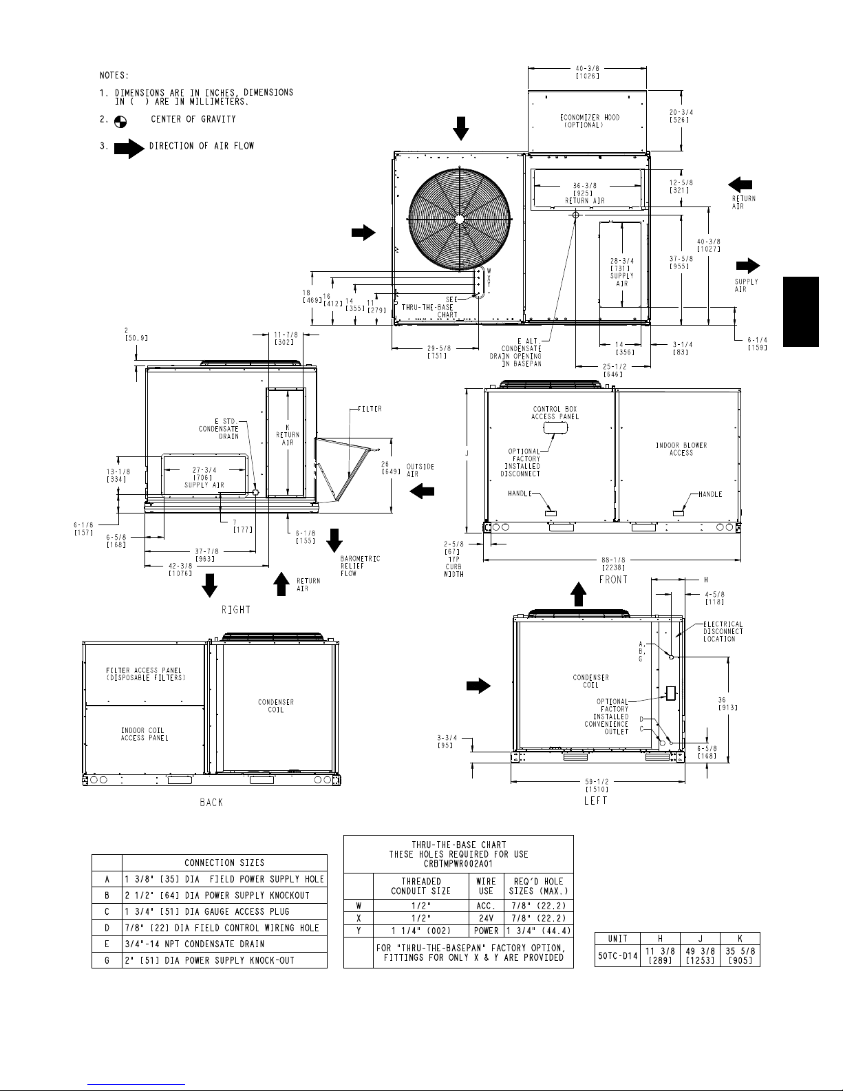
CURBS & WEIGHTS DIMENSIONS -- CHASSIS 2
50TC
C08531
Fig. 6 -- Dimensions 50TC 08-- 1 2
25
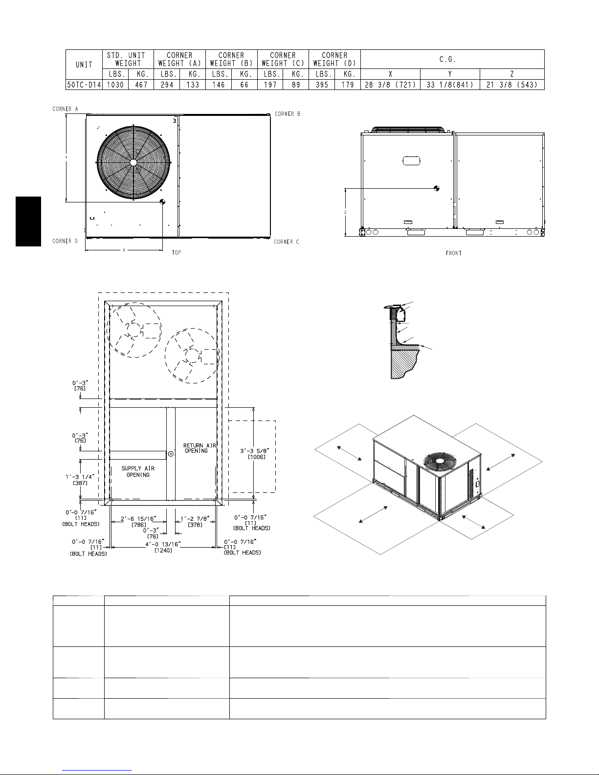
50TC
CURBS & WEIGHTS DIMENSIONS -- CHASSIS 2 (cont.)
Fig. 7 -- Dimensions 50TC 08-- 1 2
GASKET
(SUPPLIED WITH CURB)
NAIL
COUNTER FLASHING
(FIELD SUPPLIED)
ROOFING FELT
(FIELD SUPPLIED)
CANT STRIP
(FIELD SUPPLIED)
ROOFING FELT
(FIELD SUPPLIED)
C08532
Fig. 8 -- Curb Dimensions
LOC DIMENSION CONDITION
48” (1219 mm) Unit disconnect is mounted on panel
36” (914 mm) If dimension--- B is 12” (305 mm)
A
B
C
D
18” (457 mm) No disconnect, convenience outlet option
18” (457 mm) Recommended service clearance (use electric screwdriver)
12” (305 mm) Minimum clearance (use manual ratchet screwdriver)
36” (914 mm) Unit has economizer
12” (305 mm) If dimension--- A is 36” (914 mm)
Special Check for sources of flue products within 10--- ft of unit fresh air intake hood
36” (914 mm) Side condensate drain is used
18” (457 mm) Minimum clearance
42” (1067 mm) Surface behind servicer is grounded (e.g., metal, masonry wall, another unit)
36” (914 mm) Surface behind servicer is electrically non --- conductive (e.g., wood, fiberglass)
C07457
Fig. 9 -- Curb Installation Detail (Typical)
C
D
B
A
C08309
C08337
Fig. 10 -- Service Clearance
26
CURBS & WEIGHTS DIMENSIONS -- CHASSIS 3
50TC
C08533
Fig. 11 -- Dimensions 50TC--14
27
50TC
CURBS & WEIGHTS DIMENSIONS -- CHASSIS 3 (cont.)
Fig. 12 -- Dimensions 50TC--14
GASKET
(SUPPLIED WITH CURB)
NAIL
COUNTER FLASHING
(FIELD SUPPLIED)
ROOFING FELT
(FIELD SUPPLIED)
CANT STRIP
(FIELD SUPPLIED)
ROOFING FELT
(FIELD SUPPLIED)
C08534
C08309
Fig. 13 -- Curb Dimensions
LOC DIMENSION CONDITION
48” (1219 mm) Unit disconnect is mounted on panel
A
B
C
D
18” (457 mm) No disconnect, convenience outlet option
18” (457 mm) Recommended service clearance
12” (305 mm) Minimum clearance
42” (1067 mm) Surface behind servicer is grounded (e.g., metal, masonry wall)
36” (914 mm) Surface behind servicer is electrically non ---conductive (e.g., wood, fiberglass)
Special Check for sources of flue products within 10--- ft of unit fresh air intake hood
36” (914 mm) Side condensate drain is used
18” (457 mm) Minimum clearance
42” (1067 mm) Surface behind servicer is grounded (e.g., metal, masonry wall, another unit)
36” (914 mm) Surface behind servicer is electrically non ---conductive (e.g., wood, fiberglass)
C07457
Fig. 14 -- Curb Installation Detail (Typical)
C
D
B
A
C08337
Fig. 15 -- Service Clearance
28

APPLICATION DATA
Min operating ambient temp (cooling):
In mechanical cooling mode, your Carrier rooftop can
safely operate down to an outdoor ambient temperature of
40_F(4_C) and 25_F(--4_C), with an accessory winter
start kit. It is possible to provide cooling at lower outdoor
ambient temperatures by using less outside air,
economizers, and/or accessory low ambient kits.
Max operating ambient temp (cooling):
The maximum operating ambient temperature for cooling
mode is 115_F(46_C). While cooling operation above
115_F(46_C) may be possible, it could cause either a
reduction in performance, reliability, or a protective action
by the unit’s internal safety devices.
Min and max airflow (cooling mode):
To maintain safe and reliable operation of your rooftop,
operate within the cooling airflow limits. Operating above
the max may cause blow--off, undesired airflow noise, or
airflow related problems with the rooftop unit. Operating
below the min may cause problems with coil freeze--up.
Airflow:
All units are draw--though in cooling mode.
Outdoor air application strategies:
Economizers reduce operating expenses and compressor
run time by providing a free source of cooling and a
means of ventilation to match application changing needs.
In fact, they should be considered for most applications.
Also, consider the various economizer control methods
and their benefits, as well as sensors required to
accomplish your application goals. Please contact your
local Carrier representative for assistance.
Motor limits, break horsepower (BHP):
Sizing a rooftop
Bigger isn’t necessarily better. While an air conditioner
needs to have enough capacity to meet the load, it doesn’t
need excess capacity. In fact, having excess capacity
typically results in very poor part load performance and
humidity control.
Using higher design temperatures than ASHRAE
recommends for your locati on, adding “safety factors” to
the calculated load, and rounding up to the next largest
unit, are all signs of oversizing air conditioners.
Oversizing can cause short--cycling, and short cycling
leads to poor humidity control, reduced efficiency, higher
utility bills, drastic indoor temperature swings, excessive
noise, and increased wear and tear on the air conditioner.
Rather than oversizing an air conditioner, wise contractors
and engineers “right--size” or even slight ly undersize air
conditioners. Correctly sizing an air conditioner controls
humidity better; promotes efficiency; reduces utility bills;
extends equipment life, and maintains even, comfortable
temperatures.
Low ambient applications
When equipped with a Carrie r economizer, your rooftop
unit can cool your space by bringing in fresh, cool outside
air. In fact, when so equipped, accessory low--ambient kit
may not be necessary. In low ambient conditions, unless
the outdoor air is excessively humid or contaminated,
economizer--based “free cooling” is the preferred less
costly and energy conscious method.
In low ambient applications where outside air might not
be desired (such as contaminated or excessively humid
outdoor environments), your Carrier rooftop can operate
to ambient temperatures down to --20_F(--29_C) using t he
recommended accessory Motormaster low ambient
controller.
50TC
Due to Carrier’s internal unit design, air path, and
specially designed motors, the full horsepower (maximum
continuous BHP) band, as listed in Table 5, can be used
with the utmost confidence. There is no need for extra
safety factors, as Carrier’s motors are designed and
rigorously tested to use the entire, listed BHP range
without either nuisance tripping or premature motor
failure.
Winter start
Carrier’s winter start kit extends the low ambient limit of
your rooftop to 25_F(--4_C). The kit bypasses the low
pressure switch, preventing nuisance tripping of the low
pressure switch. Other low ambient precautions may still
be prudent.
29

SELECTION PROCEDURE (WITH 50TC*A07 EXAMPLE)
I. Determine cooling and heating loads.
Given:
Mixed Air Drybulb 80_F(27_C)
Mixed Air Wetbulb 67_F(19_C)
Ambient Drybulb 95_F(35_C)
TC
Load
SHC
Load
Vertical Supply Air 2100 CFM
External Static Pressure 0.66 in.wg
Electrical Characteristics 230--3--60
II. Make an initial guess at cooling tons.
Refrig. tons = TC
Refrig. tons = 69.0 / 12 = 5.75 tons
In this case, start by looking at the 50TC*A07.
50TC
III. Look up the rooftop’s TC and SHC.
Table 12 shows that, at the application’s supply air
CFM, mixed air and ambient temperatures, the
50TC*A07 supplies:
TC
SHC
= 73.7 MBH
Load
Load
= 54.4 MBH.
IV. Calculate the building Latent Heat Load.
LC
LC
=TC
Load
Load
Load
= 69.0 MBH -- 51.0 MBH = 18.0 MBH
/ 12 MBH per ton
Load
-- S H C
Load
69.0 MBH
51.0 MBH
V. Calculate RTU Latent Heat Capacity
LC = TC -- SHC
LC = 73.7 MBH -- 54.4 MBH = 19.3 MBH
VI. Compare RTU capaciti es to loads.
2,3
Compare the rooftop’s SHC and LC to the building’s
Sensible and Latent Heat Loads.
VII. Select factory options (FIOP)
Local code requires an economizer for any unit with
TC larger than 65.0 MBH.
VIII. Calculate the total static pressure.
External static pressure 0.66 in. wg
Sum of FIOP/Accessory static +0.14 in.
Total Static Pressure 0.80 in. wg
IX. Look up the Indoor Fan RPM & BHP.
Table 33 shows, at 2100 CFM & ESP= 0.8,
RPM = 1268 & BHP = 1.52
X. Determine electrical requirements
Table 52 shows the MCA and MOCP of a
50TC*A07 (without convenience outlet) as:
MCA = 30.5 amps & MOCP = 45 amps
Min. Disconnect Size: FLA = 30 & LRA = 157.
wg
LEGEND
BHP — Break horsepower
FLA — Full load amps
LC — Latent capacity
LRA — Lock rotor amp
MBH — (1,000) BTUH
MCA — Min. circuit ampacity
MOCP — Max. over --- current protection
RPM — Revolutions per minute
RTU — Rooftop unit
SHC — Sensible heat capacity
TC — Total capacity
NOTES:
1. Selection software by Carrier saves time by performing
many of the steps above. Contact your Carrier sales representative for assistance.
2. Selecting a unit with a SHC slightly lower than the
SHC
SHC’s will help control indoor humidity, and prevent temperature swings.
3. If the rooftop’s capacity meets the Sensible Heat Load,
butnottheLatentHeatLoad.
4. Indoor Fan Motor efficiency is available in Table 46. Use
the decimal form in the equation eg. 80% =.8.
is often better than oversizing. Slightly lower
Load
30
 Loading...