


 Loading...
Operation Manual
Before using the instrument, be sure to read this manual thoroughly. Keep the manual where it is easily accessible.

PLEASE NOTE
1.The user is responsible for the use and maintenance of the product. We suggest that a member of the user’s staff be designated as being in charge of maintenance so as to ensure that the product is kept in a safe and good condition.
Also, medical products must be used only by a qualified person.
2.In no event will Canon be liable for direct or indirect consequential damage arising out of the use of this product.
3.This product may malfunction due to electromagnetic waves caused by portable personal telephones, transceivers, radio-controlled toys, etc. Be sure to avoid having objects such as these, which affect this product, brought near the product.
4.Canon reserves the right to change the specifications, configuration and appearance of the product without prior notice.
© CANON INC. 2004
All rights reserved.
Under copyright laws, this manual may not be copied, in whole or in part, without the written consent of Canon.
Safety Information
Regulations
For U.S.A.
Federal law restricts this device to sale by or on the order of an ophthalmologist or optometrist.
This instrument is a CLASS I EQUIPMENT and TYPE B APPLIED PARTS according to UL2601-1.
Do not make any changes or modifications to the equipment unless otherwise specified in the manual.
If such changes or modifications should be made, you could be required to stop operation of the equipment.
NOTE: This equipment has been tested and found to comply with the limits for a Class A digital device, pursuant to Part 15 of the FCC rules.
These limits are designed to provide reasonable protection against harmful interference when the equipment is operated in a commercial environment.
This equipment generates, uses, and can radiate frequency energy and, if not installed and used in accordance with the instruction manual, may cause harmful interference to radio communications.
Operation of this equipment in a residential area is likely to cause harmful interference in with case the user will be required to correct the interference at his own expense.
Use of shielded cable is required to comply with class A limits in Subpart B of part 15 of FCC rules. The following mark shows compliance of the instrument with Directive 93/42/EEC.
For Canada
This equipment complies with the Canadian ICES-003 class A specifications.
(1)

Safety Information
General Safety Information
Follow the safety instructions in this manual and all warnings and cautions printed on the warning labels. Ignoring such cautions or warnings while handling the product may result in injury or accident. Be sure to read and fully understand the manual before this product.
Keep this manual for future reference.
|
|
Meaning of Caution Signs |
|
|
|
! |
WARNING |
This indicates a potentially hazardous situation which, if not heeded, could |
result in death or serious injury to you or others. |
||
|
|
|
! |
CAUTION |
This indicates hazardous situation which, if not heeded, may result in minor or |
moderate injury to you or others, or may result in machine damage. |
||
|
|
|
|
NOTE |
This is used to emphasize essential information. |
|
Be sure to read this information to avoid incorrect operation. |
|
|
|
|
|
|
|
Environment of Use and Storage
|
|
Do not use or store the instrument near any flammable chemicals such as |
|
|
alcohol, thinner, benzine, etc. If chemicals are spilled or evaporate, it may |
! |
WARNING |
result in fire or electric shock through contact with electric parts inside the |
|
|
instruments. Also, some disinfectants are flammable. |
|
|
Be sure to take care when using them. |
|
|
|
|
|
Do not use or store the instrument in a location with the conditions listed |
|
|
below. Otherwise, it may result in failure or malfunction, fall or cause fire or |
|
|
injury. |
|
|
- Close to facilities where water is used. |
|
|
- Where it will be exposed to direct sunlight. |
|
|
- Close to airconditioner or ventilation equipment. |
! |
WARNING |
- Close to heat source such as a heater. |
|
|
- Prone to vibration. |
|
|
- Insecure place. |
|
|
- Dusty environment. |
|
|
- Saline or sulfurous environment. |
|
|
- High temperature or humidity. |
|
|
- Freezing or condensation. |
|
|
|
|
|
Place the instrument on a firm table |
! |
CAUTION |
Do not place it extremely near the edge of the table in order to avoid damage |
|
|
or injury due to falling. |
! |
CAUTION |
Do not cover the vent holes on the cover. |
Otherwise, the temperature in the instrument may rise and cause fire. |
||
|
|
|
(2)
Safety Information
Installation Operation
Do not connect the instrument with anything other than specified. Otherwise, it may result in fire or electric shock.
Also, when other equipment is going to be connected to the instrument using ! WARNING the connector for interface, be sure to check after connection that leakage cur-
rent is within the tolerable value.
For details, please contact Canon representative or distributor.
Power Supply
! |
WARNING |
Only operate the instrument with the type of power supply indicated on the rat- |
ing label. Otherwise, it may result in fire or electric shock. |
||
|
|
|
|
|
Be sure to disconnect/connect the cables as indicated in this manual. |
|
|
The unit weighs 21 kg, so bear in mind that it may tip over if proper care is not |
! |
WARNING |
taken. |
|
|
Also, do not handle them with wet hands. Otherwise, you may get an electric |
|
|
shock that may result in death or serious injury. |
|
|
|
|
|
Securely plug in the power cable into the AC outlet. |
! |
WARNING |
If contact failure occurs, or if dust or metal object comes in contact with the |
|
|
exposed metal prong of the plug, fire or electric shock may result. |
|
|
Be sure to hold the plug or connector to disconnect the cable. |
! |
WARNING |
If you pull the cable, the core wire may be damaged, resulting in fire or electric |
|
|
shock. |
|
|
|
|
|
Do not cut or process the cables. Also, do not place anything heavy, including |
! |
WARNING |
the instrument on it, step on it, pull it, bend it, or bundle it. |
Otherwise, the cable may be damaged, which may result in fire or electric |
||
|
|
shock. |
|
|
|
! |
WARNING |
Do not get the power for more than one instrument from the same AC outlet. |
Otherwise, if may result in fire or electric shock. |
||
|
|
|
|
|
The instrument is shipped with a grounding type (three-core) power cable. |
! |
CAUTION |
To reduce the risk of electric shock, always plug the cable into a grounded |
|
|
power outlet. |
|
|
|
! |
CAUTION |
To make it easy to disconnect the plug at any time, avoid putting any obstacles |
near the outlet. |
||
|
|
|
(3)

Safety Information
Handling
! |
WARNING |
Do not measure an eye of which cornea is frail due to corneal disease or due |
to it having undergone an operation. Otherwise, complications may occur. |
||
|
|
|
|
|
Never disassemble or modify the product as it may result in fire or electric |
! |
WARNING |
shock. Also, since the instrument incorporates high-voltage parts that may |
cause electric shocks and other hazardous parts, touching them may cause |
||
|
|
death or serious injury. |
|
|
|
|
|
Do not place anything on top of the instrument. |
! |
WARNING |
Otherwise, the object may fall and cause injury. |
Also, if metal objects such as needle or clip falls into the instrument, or if liquid |
||
|
|
is spilled, it may result in fire or electric shock. |
|
|
|
|
|
When the instrument is going to be moved, be sure to turn OFF the power |
|
|
switch, unplug the power cable from the AC outlet, and disconnect other |
|
|
cables. Otherwise, cable may be damaged, which may result in fire or electric |
! |
WARNING |
shock. |
Also, when the instrument is going to be carried, be sure to support the bot- |
||
|
|
tom of the instrument an hold it horizontally. |
|
|
Do not hold it by the face rest poles or other parts, as they may come off and |
|
|
result in injury. |
|
|
|
|
|
Do not hit or drop the instrument. The instrument may be damaged if it |
! |
WARNING |
receives a strong jolt, which may result in fire or electric shock if the instru- |
|
|
ment is used without it being repaired. |
|
|
Wipe the forehead rest with ethanol or glutaraldehyde solution to disinfect it |
! |
CAUTION |
each time a different patient uses the instrument, in order to prevent infection. |
|
|
Please consult a specialist for the procedure for disinfection. |
|
|
|
! |
CAUTION |
Change the chin rest paper each time the examinee changes in order to keep |
the chin rest clean. |
||
|
|
|
|
|
Measurement head moves when the instrument is initializing or after printing |
! |
CAUTION |
the result. Do no have the examinee place his/her face on the chin rest until |
|
|
movement is completed. Otherwise, the examinee may be hurt. |
|
|
|
|
|
Set the position where to stop the measurement head with the LIMITER |
|
|
switch each time the examinee changes in order to prevent accidental contact |
|
|
of nozzle with examinee. Be sure to look from side of the examinee when |
! |
CAUTION |
deciding the stop position. If the stop position is not set correclty, the exam- |
|
|
inee may be injured. Also, if the message “LIMITER OFF” does not disappear |
|
|
even after LIMITER switch pressed several times, stop the measurement and |
|
|
contact Canon representative or distributor. |
|
|
|
! |
CAUTION |
Do not have the examinee place his/her hand or fingers under the chin rest or |
near the measurement head. Otherwise, injury may result. |
||
|
|
|
! |
CAUTION |
Do not touch the cutter of the printer. Otherwise, fingers may be cut. |
|
|
|
|
|
When the instrument is not going to be used, turn OFF the power switch. |
! |
CAUTION |
Also, unplug the power cable from the AC outlet when it is not going to be |
|
|
used for a long time. |
|
|
|
(4)
Safety Information
Handling
This instrument uses a lithium battery, which may pollute the environment if
the instrument is abandoned.
! CAUTION Please contact Canon representative or distributor before disposing of the instrument.
When Problem Occurs
|
|
Should any of the following occur, immediately turn OFF the power of each |
|
|
instrument, unplug the power cable from the AC outlet, and contact Canon |
|
|
representative or distributor. |
! |
WARNING |
- When there is smoke, odd smell or abnormal sound. |
|
|
- When liquid has been spilled into the instrument or a metal object has |
|
|
entered through an opening. |
|
|
- When the instrument has been dropped and it is damaged. |
|
|
|
Maintenance and Inspection
|
|
For safety reasons, be sure to turn OFF the power of each instrument when |
! |
WARNING |
the inspections indicated in this manual are going to be performed. |
|
|
Otherwise, it may result in electric shock. |
|
|
|
|
|
When the instrument is going to be cleaned, be sure to turn OFF the power of |
! |
WARNING |
each instrument, and unplug the power cable from the AC outlet. |
Never use benzine, thinner or any other flammable cleaning agents. |
||
|
|
Otherwise, fire or electric shock may result. |
|
|
|
|
|
Clean the plug of the power cable periodically by unplugging it from the AC |
|
|
outlet and removing dust or dirt from the plug, its periphery and AC outlet with |
! |
WARNING |
a dry cloth. If the cable is kept plugged in for a long time in a dusty, humid or |
|
|
sooty place, dust around the plug will attract moisture, and this could cause |
|
|
insulation failure which could result in a fire. |
|
|
|
! |
WARNING |
The instrument must be repaired by a qualified engineer only. |
If it is not repaired properly, it may cause fire, electric shock, or accident. |
||
|
|
|
! |
CAUTION |
For safety reasons, be sure to inspect the instrument before using it. |
|
|
|
(5)

Safety Information
Rating Label and Warning Label
The TX-F has a rating label and a warning label on it.
Contents of those and positions where they are attached are indicated below.
Warning Label 


See manual
Mirar el manual
This unit weighs 21 kg –
it may tip over if proper care is not taken.
This mark indicates that this is a Type B Applied Part according to UL2601-1/ EN60601-1.
This unit can be installed in the patient environment.
Rating Label
(6)
Contents
Safety Information ................................................................................................ |
(1) |
||
1. |
Overview ........................................................................................................ |
1 |
|
2. |
Notes for Using the Instrument ...................................................................... |
2 |
|
3. |
Description ..................................................................................................... |
3 |
|
|
3.1 |
Main Unit ...................................................................................................................... |
3 |
|
3.2 |
Connectors under the Main Unit .................................................................................. |
5 |
|
3.3 |
Operation Panel ........................................................................................................... |
6 |
|
3.4 |
Display on Measurement Screen ................................................................................. |
8 |
|
3.5 |
Display on DISPLAY and SET Modes Screens ........................................................... |
11 |
4. |
Measurement Modes ..................................................................................... |
12 |
|
|
4.1 |
Measurement Modes ................................................................................................... |
12 |
|
4.2 |
Relation between Settings and Measurement Operation ............................................ |
13 |
5. |
Measurement ................................................................................................. |
15 |
|
|
5.1 |
Preparation .................................................................................................................. |
15 |
|
5.2 |
FULL AUTO/AUTO Measurement ............................................................................... |
20 |
|
5.3 |
MANUAL Measurement ............................................................................................... |
27 |
6. |
Measurements Stored in Memory [DISPLAY Mode] ...................................... |
31 |
|
7. Various Settings [SET Mode] ......................................................................... |
32 |
|
7.1 |
Settings for Measurement (Page: 1/3) ......................................................................... |
33 |
7.2 |
Settings for Printing and Transfer (Page: 2/3) ............................................................. |
36 |
7.3 |
Entering Message for Internal Printer (Page: 3/3) ....................................................... |
39 |
8. Daily Inspection and Maintenance ................................................................. |
43 |
|
8.1 |
Inspection .................................................................................................................... |
43 |
8.2 |
Before Calling a Service Person .................................................................................. |
45 |
8.3 |
Cleaning and Disinfection ............................................................................................ |
51 |
8.4 |
Replacement ................................................................................................................ |
55 |
8.5 |
Expendable Parts List .................................................................................................. |
59 |
9. |
Installation ...................................................................................................... |
60 |
|
|
9.1 |
Installation .................................................................................................................... |
60 |
|
9.2 |
Precautions when Moving the Instrument .................................................................... |
62 |
10. |
Service Information ...................................................................................... |
63 |
|
11. |
Specifications ............................................................................................... |
64 |
|
12. |
Components ................................................................................................. |
66 |
|
1. Overview
The Canon Full Auto Tonometer TX-F is an instrument for measuring intraocular pressure without making contact with examinee’s eye.
Just by displaying the examinee’s eye somewhere on the monitor and pressing the START switch, the TX-F then automatically performs alignment and measurement by a three dimensional tracking system.
Measurement mode can be selected
The examiner can select a measurement mode from three modes: FULL AUTO, AUTO and
MANUAL.
In FULL AUTO mode, measurement of both eyes will be performed automatically. Also, the result can be selected to be printed automatically after measuring both eyes. Thus, full measurement can be done very easily in a short time.
In AUTO mode, alignment and measurement will automatically be performed once each time the START switch is pressed. Thus, you can perform measurement after checking the condition of examinee’s eye each time. Also, you can measure the eye as many times as required.
In MANUAL mode, measurement can be performed manually when examinee’s pupil is eccentric, or when measurement is apt to result in error.
Observation range of examinee’s eye on the monitor has been widened and the depth of focus is deep
It is easier to check the position of the eye or whether eyelashes are covering the pupil.
Level meter will be displayed
The TX-F obtains intraocular pressure from the waveform of the signal obtained by detecting light reflected from the cornea when air is blown onto the eye.
However, when the reflected light is obscured by the eyelid or eyelashes, the waveform of the signal becomes low, reducing the reliability of the measurement value.
The level of the waveform can be displayed in four steps as a mark (“level meter”) on the measurement mode screen, display mode screen and the printout by the setting in SET mode. Thus, the level meter can be used to check the reliability of the measured values.
When error has occurred, image will be displayed immediately on the monitor
This makes it easier to determine the cause of the measurement error.
Also, the eyelid warning line on the warning image will enable you to see if the eyelid or eyelashes were too low during measurement. If the eyelid or eyelashes are below the line, help the examinee open the eye wide by gently holding up the upper eyelid with your fingers.
– 1 –

2. Notes for Using the Instrument
Before Use
(1)Sudden heating of the room in cold ares will cause condensation to form on the protective glass in the measurement window and on optical parts inside the instrument. In this case, wait until condensation disappears before performing measurement.
During Measurement
(1)Before measurement, explain about the measurement that is going to be performed to the examinee so he/she will not be surprised by a sudden air puff. Demonstrate the intensity of the air puff by having the examinee place a finger in front of the nozzle and pressing the CLEAR (DEMO) switch for more than 2 seconds.
(2)Measurement head automatically moves after the power is turned ON. Do not prevent movement of measurement head by holding it or placing something near it.
(3)It is recommended that a hard copy of the printout be made if you wish to store it for a long time, because printouts on thermal paper are apt to deteriorate.
After Use
(1)Turn OFF the power, put the cap over the nozzle in order to prevent dust from attaching to it, and place the dust cover over the instrument.
During Cleaning and Disinfection
(1)If the surface of the objective lens on the nozzle is wiped when dust or dirt is on it, it will be scratched. Also, do not wipe the objective lens with ethyl alcohol or with cleaning paper containing silicone. Otherwise, the surface will be corroded, or will be stained. See section 8.3.2.
(2)Do not use alcohol, benzine or thinner for cleaning the cover of the instrument. Also, never wipe the cover with ethanol or glutaraldehyde solution. Otherwise, coating will be corroded. See section 8.3.4.
Environment of Use
(1)After a long time of use, dust in the air will attach not only on the nozzle, but also on optical parts inside the instrument, which may cause incorrect measurement, Always keep the room clean.
During Installation
(1)Handle the instrument carefully, as preadjustment may be altered if the instrument receives a strong jolt.
(2)Do not install the instrument where it will be exposed to direct sunlight. Otherwise, it will be hard to see the monitor properly, or you may not be able to obtain a correct measurement.
(3)Blow off the dust in the connectors of the cables with a blower before connecting them. Otherwise, connection failure may occur.
(4)Do not lay the instrument on its side when the power is turned ON. Otherwise, the instrument will malfunction.
(5)When the instrument is going to be transported, it must be protected against vibration and shocks. Contact Canon representative or distributor for advice on the procedure for packing it.
–2 –

3. Description
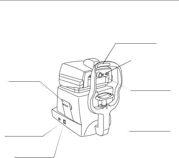
3.1 Main Unit
3.1.1 Examiner’s Side
Height adjustment mark
Align the height of the examinee’s eye with this mark by adjusting the height of chin rest.
Contrast adjuster
Adjusts contrast of monitor.
Measurement head
Unit that performs measurement.
Monitor
Displays the screen for measurements and various settings.
Operation panel
See section 3.3.
Brightness adjuster
Adjusts brightness of monitor.
– 3 –
3.1 Main Unit
3.1.2 Examinee’s Side
Printer
Prints measurements.
Rating label
Name of the product, rated voltage, serial number, etc. are indicated on the label.
Power switch
Switch for turning power
ON and OFF.
Forehead rest
Place the examinee’s forehead against this rest.
External eye fixation lamp
Lamp to be used when the examinee’s eye cannot be fixed by the internal eye fixation lamp.
Nozzle
Supplies air used for measurement.
Must be always kept clean.
Chin rest
Place the examinee’s chin on this rest.
– 4 –
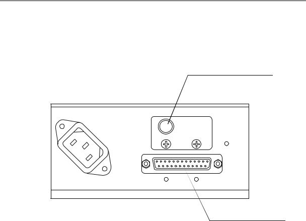
3.2 Connectors under the Main Unit
3.2 Connectors under the Main Unit
Power supply connector
Connector for the power supply cable.
Grounding terminal
Terminal for grounding the instrument.
RS232C Connector
RS232C connector for connecting external instrument. External instrument must be connected in compliance with the IEC601-1-1 standard.
– 5 –
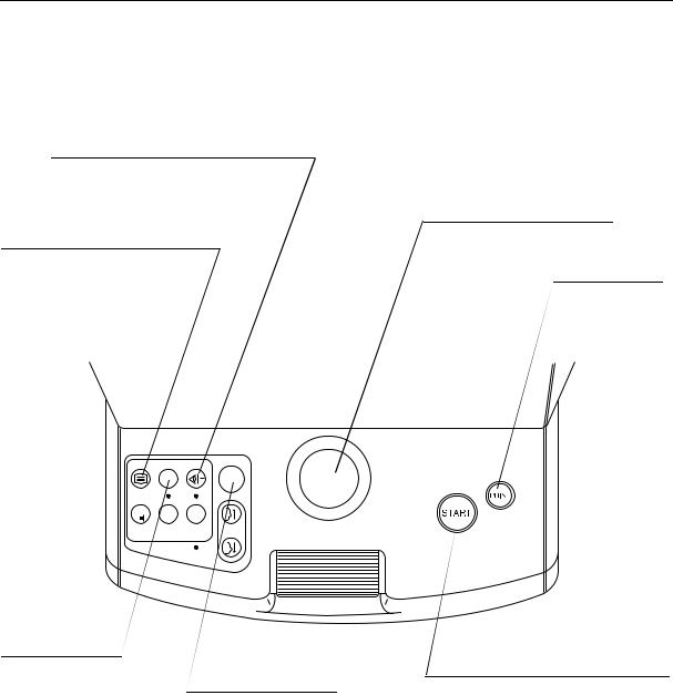
3.3 Operation Panel
3.3 Operation Panel
LIMITER switch
Switch for stopping the measurement head in a certain position in order to prevent the nozzle accidentally hitting the examinee’s eye.
DISP./SET switch
Press this switch in order to enter DISPLAY mode, where you can see measurement data stored in memory. You can enter SET mode, where various settings can be made, from DISPLAY mode.
DISP
IN/EX  R
R L
L
A/M
AUTO/ |
CHIN REST |
MANU. |
|
READY |
|
Trackball
Moves the measurement head up and down, right and left.
PRINT switch
Press this switch in order to print or transfer the measurement manually.
FIXATION switch
Each time the switch is pressed, the eye fixation lamp switches between internal and external.
When the external eye fixation lamp is ON, the lamp below the switch lights.
R/L switch
Each time the switch is pressed, the measurement head moves either to the right or left eye.
START switch
When this switch is pressed in FULL AUTO or AUTO mode, automatic alignment and measurement are performed. In MANUAL mode, only measurement is performed.
– 6 –
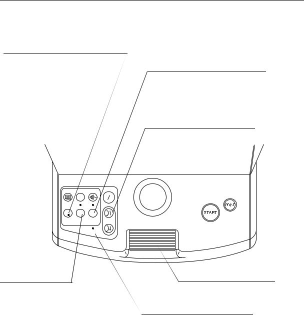
3.3 Operation Panel
CLEAR (DEMO) switch
This switch has two functions.
If printing is not necessary after the measurement, press this switch for an instant. Displayed measurement will be deleted, clearing the display for the next examinee. Or, if the switch is pressed for more than two seconds, air will be emitted from the nozzle for demonstrations of air puff.
DISP./SET |
FIXATION |
LIMITER |
|
|
IN/EX |
|
R L |
C |
3/1 |
A/M |
|
|
|
||
CLEAR |
PUFF |
AUTO/ |
CHIN REST |
(DEMO) |
TIMES |
MANU. |
|
|
|
READY |
|
AUTO/MANU. switch
Press this switch to select measurement mode (FULL AUTO/AUTO/MANUAL). The selected mode will be displayed on the upper left side of the monitor. Lamp above the switch lights when FULL AUTO or AUTO mode is selected.
CHIN REST switches
 Switches for raising/lowering the chin rest.
PUFF TIMES switch
Each time the switch is  pressed, the number of times of measurement (1 or 3) in FULL AUTO mode can be selected. The number of times will be displayed within the brackets next to “FULL AUTO”.
Roller
 Moves the measurement head back and forth.
READY lamp
 It is ON when the instrument is ready for measurement, and blinks during initialization or when power-saving system is operating.
– 7 –

3.4 Display on Measurement Screen
3.4 Display on Measurement Screen
The screen below is an example when FULL AUTO mode is selected.
3.4.1 Before Measurement
|
Number of times of measurement |
|
|
|
|
|
|
|
|
|
|
|
|
|||
|
The number of times of measurement (1 or 3) to be per- |
|
|
|
|
|
|
|
|
|||||||
|
formed in FULL AUTO mode is displayed. |
|
|
|
|
|
|
|
|
|
|
|||||
|
It is not displayed in AUTO and MANUAL mode. |
|
|
|
Serial number |
|
||||||||||
|
Number of times can be selected by pressing PUFF |
|
|
|
||||||||||||
|
|
|
|
Serial number is displayed when “COUNT” |
||||||||||||
|
TIMES switch. |
|
|
|
|
|
|
|||||||||
|
|
|
|
|
|
|
on page 1/3 of SET mode is set to “ON”. |
|||||||||
|
|
|
|
|
|
|
|
|
|
|
The initial value can also be set from the |
|||||
|
Measurement mode |
|
|
|
|
|
|
same page of SET mode. |
||||||||
|
|
|
|
|
|
|
|
|
|
|
|
|
||||
|
Measurement mode (FULL |
|
|
|
|
|
|
|
|
|
|
|
|
|
||
|
AUTO, AUTO or MANUAL) is |
|
|
|
|
|
|
|
|
|
|
|
|
|||
|
displayed. Measurement mode can |
|
|
|
|
|
|
|
|
|
Condition of limiter |
|||||
|
be selected with AUTO/MANU. |
|
|
|
|
|
|
|
|
|
||||||
|
|
|
|
|
|
|
|
|
|
When the limiter for preventing the |
||||||
|
switch. |
|
3 0 |
|
|
L I M I T E R O F F |
|
|||||||||
|
|
|
|
|
nozzle from coming into contact |
|||||||||||
|
|
|
|
|
FULLAUTO(3) |
|
N o . 0 0 0 0 0 1 |
|
|
|
|
|
||||
|
|
|
|
|
|
|
|
|
|
|
|
|
with examinee’s eye is not working, |
|||
|
|
|
|
|
|
|
|
|
|
|
|
|
message “LIMITER OFF” will be dis- |
|||
Order of displaying the result |
|
|
|
|
|
|
|
|
|
|
played. |
|||||
|
|
|
|
|
|
|
|
|
Limiter can be set to ON/OFF with |
|||||||
Order of displaying the result (“ ” |
|
|
|
|
|
|
|
|
|
|||||||
|
|
|
|
|
|
|
|
|
LIMITER switch. See section 5.1. |
|||||||
for reliability or “ ” for sequence) |
|
|
|
|
|
|
|
|
|
|||||||
|
|
|
|
|
|
mmHg |
|
|
|
|
|
|||||
is shown. Order can be selected |
|
|
|
|
|
|
|
|
|
|
|
|||||
|
|
|
|
|
|
|
|
|
|
|
|
|
|
|
||
from “ORDER” on page 1/3 of SET |
|
|
|
|
|
|
STD |
|
|
|
|
|
||||
|
R |
|
[ |
, |
, |
] |
|
|
|
|
|
|
||||
mode. |
|
L |
[ |
, |
, |
] |
|
|
|
|
|
|
||||
|
|
|
|
|
|
|
|
|
|
|
|
|
|
Unit of intra-ocular pressure |
||
|
Measurement range |
|
|
|
|
|
|
|
|
|||||||
|
|
|
|
|
|
|
|
|
|
|
|
|
||||
|
Measurement range (“30” for 0 – |
|
|
|
|
|
|
|
|
|
|
|
|
|
||
|
30 mmHg or “60” for 25 – 60 |
|
|
|
|
|
|
|
Alignment ring |
|||||||
|
mmHg) is displayed. It can be |
|
|
|
|
|
|
|
|
|
||||||
|
|
|
|
|
|
|
|
This is the ring used for |
||||||||
|
selected from “RANGE” on page |
|
|
|
|
|
|
|
positioning the examinee’s |
|||||||
|
1/3 of SET mode. |
|
|
|
|
|
|
|
pupil during manual mea- |
|||||||
|
|
|
|
|
|
|
|
|
|
|
|
surement. |
||||
Right or left side eye
The display of the side of the eye where the measurement head is positioned will be reversed.
– 8 –
3.4 Display on Measurement Screen
3.4.2 After Measurement
When measurement has been done normally
Serial number
Serial number counts up after printing, transferring or deleting the data, or after function is restored from the power-saving mode if “COUNT” on page 1/3 of SET mode is set to “ON”.
|
FULLAUTO(3) |
|
|
N o . 0 0 0 0 0 1 |
|
|
|
|
|
|
|
|
|
|
|
|
|
|
|
|
||||||||||
|
|
3 0 |
|
|
|
|
|
|
|
|
|
|
|
|
|
|
|
|
|
|
|
|
|
|
STD value |
|||||
|
|
|
|
|
|
|
|
|
|
|
|
|
|
|
|
|
|
|
|
|
|
|
|
|
||||||
|
|
|
|
|
|
|
|
|
|
|
|
|
|
|
|
|
|
|
|
|
|
|
|
|
The value calculated from measurement data (maximum |
|||||
|
|
|
|
|
|
|
|
|
|
|
|
|
|
|
|
|
|
|
|
|
|
|
|
|
of 10 data) in memory is displayed. The upper data is the |
|||||
|
|
|
|
|
|
|
|
|
|
|
|
|
|
|
|
|
|
|
|
|
|
|
|
|
right side eye’s STD value, and the lower one is the left |
|||||
|
|
|
|
|
|
|
|
|
|
|
|
|
|
|
|
|
|
|
|
|
|
|
|
|
side eye’s value. |
|||||
|
|
|
|
|
|
|
|
|
|
|
|
|
mmHg |
|
|
|
|
|
|
|
|
|
|
After the first measurement: |
||||||
|
|
|
|
|
|
|
|
|
|
|
|
|
|
|
|
|
|
|
|
|
|
|
Value to the first decimal place |
|||||||
|
|
|
|
|
|
|
|
|
|
|
|
|
|
STD |
|
|
|
|
|
|
|
|
|
|
||||||
|
R |
|
|
[ |
17 |
, |
8 |
, |
7 |
] |
7.2 |
|
|
|
|
|
|
|
|
|
|
After the second measurement: |
||||||||
|
|
|
|
|
|
[ |
9 |
, |
9 |
, |
8 |
] |
8.9 |
|
|
|
|
|
|
|
|
|
|
Value with higher reliability |
||||||
|
L |
|||||||||||||||||||||||||||||
|
|
|
|
|
|
|
||||||||||||||||||||||||
|
|
|
|
|
|
|
|
|
|
|
|
|
|
|
|
|
||||||||||||||
|
|
|
|
|
|
|
|
|
|
|
|
|
|
|
|
|
|
|
|
|
|
|
|
|
After more than three measurements: |
|||||
|
|
|
|
|
|
|
|
|
|
|
|
|
|
|
|
|
|
|
|
|
|
|
|
|
The most appropriate value “standard value” obtained |
|||||
|
|
|
|
|
|
|
|
|
|
|
|
|
|
|
|
|
|
|
|
|
|
|
|
|
by reliability and statistically processing the data. |
|||||
|
|
|
|
|
|
|
|
|
|
|
|
|
|
|
|
|
|
|
|
|
|
|
|
|
However, measurement with low reliability mark (*) |
|||||
|
|
|
|
|
|
|
|
|
|
|
|
|
|
|
|
|
|
|
|
|
|
|
|
|
will not be included in the calculation. |
|||||
|
|
|
|
|
|
|
|
|
|
|
|
|
|
|
|
|
|
|
|
|
|
|
|
|
Measurement data |
|||||
|
|
|
|
|
|
|
|
|
|
|
|
|
|
|
|
|
|
|
|
|
|
|
|
|
Maximum of three measurements are displayed in the |
|||||
|
|
|
|
|
|
|
|
|
|
|
|
|
|
|
|
|
|
|
|
|
|
|
|
|
order set from “ORDER” on page 1/3 of SET mode. |
|||||
|
|
|
|
|
|
|
|
|
|
|
|
|
|
|
|
|
|
|
|
|
|
|
|
|
The upper row is the data of the right side eye, and the |
|||||
|
|
|
|
|
|
|
|
|
|
|
|
|
|
|
|
|
|
|
|
|
|
|
|
|
lower row is the data of the left side eye. |
|||||
|
|
|
|
|
|
|
|
|
|
|
|
|
|
|
|
|
|
|
|
|
|
|
|
|
Maximum of 10 measurements for each eye can be seen in |
|||||
|
|
|
|
|
|
|
|
|
|
|
|
|
|
|
|
|
|
|
|
|
|
|
|
|
DISPLAY mode. See chapter 6. |
|||||
|
|
|
|
|
|
|
|
|
|
|
|
|
|
|
|
|
|
|
|
|
|
|
|
|
Low reliability mark (*) |
|||||
|
|
|
|
|
|
|
|
|
|
|
|
|
|
|
|
|
|
|
|
|
|
|
|
|
Mark that appears when the reliability of the measurement |
|||||
|
|
|
|
|
|
|
|
|
|
|
|
|
|
|
|
|
|
|
|
|
|
|
|
|
has been determined to be low after multiple measurement |
|||||
|
|
|
|
|
|
|
|
|
|
|
|
|
|
|
|
|
|
|
|
|
|
|
|
|
values have been statistically analyzed. |
|||||
|
|
|
|
|
|
|
|
|
|
|
|
|
|
Level meter |
||||||||||||||||
|
|
|
|
|
|
|
|
|
|
|
|
|
|
Level meter is a mark that shows the level of the waveform of the signal |
||||||||||||||||
|
|
|
|
|
|
|
|
|
|
|
|
|
|
obtained by detecting light reflected from the cornea when air is blown onto |
||||||||||||||||
|
|
|
|
|
|
|
|
|
|
|
|
|
|
the eye. |
|
|
|
|
|
|
|
|
|
|
|
|
|
|
|
|
|
|
|
|
|
|
|
|
|
|
|
|
|
|
|
|
|
|
|
|
|
|
|
|
The height of the signal waveform was high. |
||||||
|
|
|
|
|
|
|
|
|
|
|
|
|
|
|
|
|
|
|
|
|
|
|
|
The height of the signal waveform was low. |
||||||
|
|
|
|
|
|
|
|
|
|
|
|
|
|
|
|
|
|
|
|
|
|
|
|
|||||||
|
|
|
|
|
|
|
|
|
|
|
|
|
|
|
|
|
|
|
|
|
|
|
|
|||||||
|
|
|
|
|
|
|
|
|
|
|
|
|
|
When reflected light is obscured by the eyelid or eyelashes, the waveform of |
||||||||||||||||
|
|
|
|
|
|
|
|
|
|
|
|
|
|
the signal becomes low, reducing the reliability of the measurement value. |
||||||||||||||||
|
|
|
|
|
|
|
|
|
|
|
|
|
|
Therefore, the level meter can be used to check the reliability of the measured |
||||||||||||||||
|
|
|
|
|
|
|
|
|
|
|
|
|
|
values. |
|
|
|
|
|
|
|
|
|
|
|
|
|
|
|
|
|
|
|
|
|
|
|
|
|
|
|
|
|
|
To display the level meter, set “( |
|
|
) LEVEL” to ON as described on page 2/3 |
|||||||||||||
|
|
|
|
|
|
|
|
|
|
|
|
|
|
|
||||||||||||||||
|
|
|
|
|
|
|
|
|
|
|
|
|
|
|
||||||||||||||||
|
|
|
|
|
|
|
|
|
|
|
|
|
|
|||||||||||||||||
|
|
|
|
|
|
|
|
|
|
|
|
|
|
of SET mode. Level meter of the |
|
|
|
|
newest measurement will be displayed on the |
|||||||||||
|
|
|
|
|
|
|
|
|
|
|
|
|
|
measurement mode screen. Level meter of all the measured values can be seen |
||||||||||||||||
|
|
|
|
|
|
|
|
|
|
|
|
|
|
in the display mode screen. |
||||||||||||||||
|
|
|
|
|
|
|
|
|
|
|
|
|
|
NOTE: |
Maximum level of the level meter differs for each eye, due to differ- |
|||||||||||||||
ences in corneal reflection rates.
– 9 –
3.4 Display on Measurement Screen
When measurement error has occurred
FULLAUTO(3) |
N o. 0 |
0 |
0 |
0 0 1 |
|
3 0 |
|||||
|
|
|
|
mmHg STD
R ERROR |
[ |
, |
, |
] |
L |
[ |
, |
, |
] |
Eyelid warning line
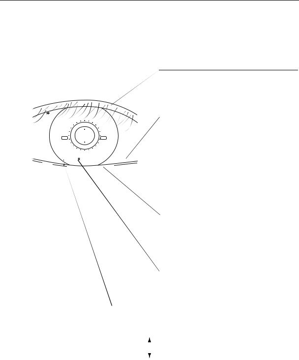
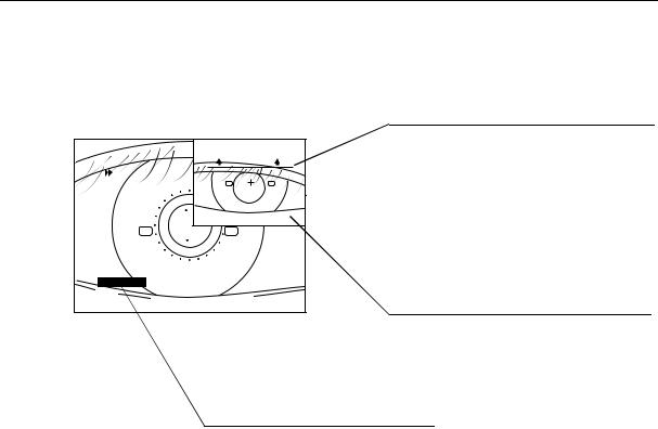
 If the eyelid or eyelashes are below the eyelid warning line on the image, instruct the examinee to keep the eye open wide, or help them open their eye wide.
Warning image
Eye front image when measurement error has occurred will be displayed if “WARNING IMG” is set to “ON” on page 1/3 of SET mode.
Warning image will not be displayed when error is caused by blinking or when result is over the measurement range, etc.
ERROR display
“ERROR” is displayed when measurement was a failure. Take the required measures and try again.
– 10 –
3.5 Display on DISPLAY and SET Modes Screens
3.5 Display on DISPLAY and SET Modes Screens
In DISPLAY and SET modes, a diagram showing the switches and their functions for the operation will be displayed on the lower part of the monitor, because the functions differ from that screen in the display of the switches.
The diagram corresponds to the switches on the operation panel as follows:
LIMITER switch
FIXATION switch
DISP./SET switch
CLEAR (DEMO) switch PUFF TIMES switch AUTO/MANU. switch
|
DISPLAY |
MODE |
|
|
I O P |
R E L I A B I L |
mmHg |
||
|
R I G H T |
|
L E F T |
|
1 |
8 |
|
9 |
|
2 |
7 |
|
9 |
|
3 |
1 7 |
|
8 |
R/L switch |
4 |
|
|
|
|
5 |
|
|
|
|
6 |
|
|
|
Trackball |
7 |
|
|
|
|
8 |
|
|
|
|
9 |
|
|
|
PRINT switch |
1 0 |
|
|
|
|
S T D [ |
7 . 2 |
|
8 . 9 |
] |
SET |
CLEAR |
|
||
END |
|
|
|
START switch |
|
|
|
|
Roller |
|
|
|
|
CHIN REST |
|
|
|
|
switches |
– 11 –

4. Measurement Modes
4.1 Measurement Modes
There are three modes for performing measurement: FULL AUTO, AUTO and MANUAL. Measurement mode can be selected with the AUTO/MANU. switch.
However, in the following cases, FULL AUTO or AUTO mode will automatically be selected according to the “DEFAULT” setting in SET mode no matter what modes has been selected:
–After power is turned ON
–After PRINT switch is pressed
–After CLEAR (DEMO) switch is pressed to delete measurement data
–After returning to measurement mode from power-saving mode
FULL AUTO Mode
After displaying the examinee’s eye on the monitor, the examiner presses the start switch. The instrument will then automatically perform alignment, focusing and measurement. After measuring one eye, the instrument automatically measured the other eye in turn. By setting the options in SET mode as follows, the result will automatically be printed after both eyes have been measured, and the measurement head will return to the initial position:
“PRINT: ON” (See section 7.2) “AUTO PRINT: ON” (See section 7.2)
AUTO Mode
In the same way as in FULL AUTO mode, the examiner presses the START switch after displaying the examinee’s eye on the monitor. However, the instrument will automatically perform alignment, focusing and measurement only once. Press the START switch if you wish to repeat measurement.
It is recommended that AUTO mode be selected where the examiner wishes to check the condition of the examinee’s eye each time before starting the measurement in cases such as when the examinee cannot keep his/her eye open.
Press the R/L switch to move the measurement head to the opposite side if you wish to measure the other eye.
Press the PRINT switch to print out the result.
MANUAL Mode
Select MANUAL mode when the pupil is eccentrics, or when measuring a certain examinee is apt to result in error in FULL AUTO or AUTO mode.
In MANUAL mode, the examiner must perform precise alignment and focus manually, and then press the START switch to measure. Result will be printed by pressing the PRINT switch. However, after printing the result or deleting the data, the instrument will return to FULL AUTO or AUTO mode.
– 12 –

4.2Relation between Settings and Measurement Operation
4.2Relation between Settings and Measurement Operation
The measurement operation differs according to the combination of measurement mode and settings selected in SET mode.
The following table shows typical examples of combinations.
|
|
|
Settings |
|
|
|
|
|
|
|
|
|
|
|
|
Measur |
|
SET Mode |
|
|
|
||
ement |
|
|
|
|
|
Measurement Operation |
Use |
Mode |
|
|
|
|
|
|
|
(AUTO/ |
DE- |
AUTO |
TRANS |
|
|
||
MANU. |
FAULT |
|
|
||||
|
|
|
|
||||
switch |
|
|
|
|
|
|
|
|
|
|
|
|
|
|
|
|
|
|
|
|
|
|
|
|
|
FULL |
|
|
|
After measuring both eyes automati- |
|
|
|
|
|
|
cally as many times as set, result will |
To have the result printed |
|
|
|
AUTO |
ON |
ON |
ON |
automatically be printed and trans- |
and transferred automati- |
|
|
/ |
ferred. |
cally after full automatic |
|||
|
|
|
|
|
|||
|
|
AUTO |
|
|
|
Then, measurement head returns to the |
measurement. |
FULL |
|
|
|
|
initial position. |
|
|
|
|
|
|
|
|
||
AUTO |
|
FULL |
|
|
|
Both eyes will automatically be mea- |
|
|
|
|
|
|
|
||
|
|
|
|
|
sured as many times as set. |
To transfer but not print |
|
|
|
AUTO |
OFF |
OFF |
ON |
Result will be transferred by pressing |
|
|
|
the result after full auto- |
|||||
|
|
/ |
PRINT switch. |
||||
|
|
|
|
|
matic measurement. |
||
|
|
AUTO |
|
|
|
Then, measurement head returns to the |
|
|
|
|
|
|
|
||
|
|
|
|
|
|
initial position. |
|
|
|
|
|
|
|
|
|
|
|
FULL |
|
|
|
One eye will automatically be measured |
|
|
|
|
|
|
once. If you wish to measure the other |
To print and transfer the |
|
|
|
AUTO |
ON |
ON/ |
ON |
eye, press R/L switch and then START |
|
|
|
result after automatic |
|||||
|
|
/ |
OFF |
switch. |
|||
|
|
|
|
measurement. |
|||
|
|
AUTO |
|
|
|
Result will be printed and transferred |
|
|
|
|
|
|
|
||
AUTO |
|
|
|
|
|
by pressing PRINT switch. |
|
|
|
|
|
|
|
|
|
|
FULL |
|
|
|
One eye will automatically be measured |
|
|
|
|
|
|
|
|
||
|
|
|
|
|
once. If you wish to measure the other |
To transfer but not print |
|
|
|
AUTO |
OFF |
ON/ |
ON |
eye, press R/L switch and then START |
|
|
|
the result after automatic |
|||||
|
|
/ |
OFF |
switch. |
|||
|
|
|
|
measurement. |
|||
|
|
AUTO |
|
|
|
Result will be transferred by pressing |
|
|
|
|
|
|
|
||
|
|
|
|
|
|
PRINT switch. |
|
|
|
|
|
|
|
|
|
– 13 –

4.2 Relation between Settings and Measurement Operation
|
|
|
Settings |
|
|
|
|
|
|
|
|
|
|
|
|
Measur |
|
SET Mode |
|
|
|
||
ement |
|
|
|
|
|
Measurement Operation |
Use |
Mode |
|
|
|
|
|
|
|
(AUTO/ |
DE- |
AUTO |
TRANS |
|
|
||
MANU. |
FAULT |
|
|
||||
|
|
|
|
||||
switch |
|
|
|
|
|
|
|
|
|
|
|
|
|
|
|
|
|
|
|
|
|
|
|
|
|
|
|
|
|
Alignment and measurement are per- |
|
|
|
|
|
|
|
formed manually. Result is printed and |
|
|
|
FULL |
|
ON/ |
|
transferred by pressing PRINT switch. |
To print and transfer the |
|
|
ON |
ON |
Then, the measurement head returns to |
result after manual mea- |
||
|
|
AUTO |
OFF |
initial position. |
surement from FULL |
||
|
|
|
|
||||
|
|
|
|
|
|
After printing/transferring/deleting the |
AUTO mode. |
|
|
|
|
|
|
result, instrument returns to FULL |
|
MAN- |
|
|
|
|
AUTO mode. |
|
|
|
|
|
|
|
|
||
UAL |
|
|
|
|
|
Alignment and measurement are per- |
|
|
|
|
|
|
|
|
|
|
|
|
|
|
|
formed manually. Result is printed and |
|
|
|
|
|
ON/ |
|
transferred by pressing PRINT switch. |
To print and transfer the |
|
|
AUTO |
ON |
ON |
Then, the measurement head returns to |
result after manual mea- |
|
|
|
OFF |
initial position. |
surement from AUTO |
|||
|
|
|
|
|
|||
|
|
|
|
|
|
After printing/transferring/deleting the |
mode. |
|
|
|
|
|
|
result, instrument returns to AUTO |
|
|
|
|
|
|
|
mode. |
|
|
|
|
|
|
|
|
|
– 14 –
Loading...