


VER
Documentazione
Tecnica
35
rev. 3.3
01/2001
©
CAME
CANCELLI
AUTOMATICI
CANCELLI AUTOMATICI
VER
Automazione con sistema a traino per porte basculanti e sezionali
Automatic traction system for overhead and sectional doors
Automatisme avec sistéme "a traction" pour portes basculantes et sectionnels
Schubantriebssistem für Schwing-und Sektionaltore
Automatización con sistema "por arrastre" para puertas basculantes y seccionales
119E35
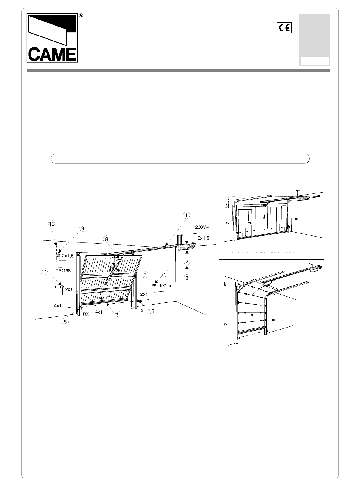
Impianti tipo -
Standard installations -
Installation type
- Standard Montage -
Instalaciòn tipo
1. Gruppo VER
2. Quadro comando
incorporato
Accessori
3. Ricevitore radio
4. Pulsantiera da
interno
5. Fotocellule di
sicurezza
6. Costola a raggi
infrarossi
7. Braccio adattatore
8. Dispositivo di
sblocco
9. Lampeggiatore
10. Antenna
11. Selettore a chiave
1. VER unit
2. Incorporated control
panel
Accessories
3. Radio receiver
4. Internal pushbutton
array
5. Safety photocells
6. Infrared rib
7. Adaptor arm
8. Release mechanism
9. Flashing light
10. Antenna
11. Key-operated selector
switch
1. Groupe VER
2. Armoire de
commande
incorporée
Accessoires
3. Récepteur radio
4. Poussoirs internes
5. Photocellules de
sécurité
6. Profil de sécurité à
rajons infrarouges
7. Bras adaptateur
8. Dispositif de
déblocage
9. Clignotant
10. Antenne
11. Sélecteur à clé
1
1. VER-Antriebsmotor
2. Intergrierte
motorsteuerung
Zubehör
3. Funkempfänger
4. Schalteinheit für
Innenmontage
5. Lichtschanken
6. Infrarot
Sicherheitsleiste
7. Adapterarm
8. Entriegelungssjstem
9. Blinkleuche
10. Antenne
11. Schlüsselschalter
1. Conjunto VER
2. Cuadro de
mando
incorporado
Accesorios
3. Radiorreceptor
4. Botonera interior
5. Fotocélulas de
seguridad
6. Protector por
infrarrojos
7. Brazo adaptador
8. Dispositivo de
desbloqueo
9. Lámpara intermitente
10. Antena
11. Selector a llave
CARATTERISTICHE GENERALI -
ALLGEMEINES DATEN
GENERAL SPECIFICATIONS
- CARACTERÍSTICAS GENERALES
- CARACTÉRISTIQUES GÉNÉRALÉS
Progettato e costruito interamente dalla CAME
S.p.A. e rispondente alle
vigenti norme di sicurezza (UNI 8612).
Garantito 12 mesi salvo
manomissioni.
LIMITI D'IMPIEGO:
Motoriduttori con quadro
comando incorporato,
adatti a motorizzare portoni sezionali (fig. A,
pag 4), porte basculanti a
molle (fig. B, pag 4) fino a
2,70 m. di altezza, e porte
basculanti a contrappesi
(fig. C, pag 4) fino a 2,50
m. di altezza; vedere la
voce “ACCESSORI DI
COMPLETAMENTO
” (pag 4) per
eventuali adattamenti.
Designed and built entirety
by CAME S.p.A. in full
compliance with current
safety standards (UNI
8612).
Guaranteed for 12 months
unless tampered with.
OPERATING LIMITS:
Gearmotor with built-in
control panel, suitable for
sectional doors (fig. A,
page 4), spring-batanced
overhead doors (fig. B,
page 4) up to 2, 70 m. door
height and over-head doors
with counterweight balancing (fig. C, page 4) up to
2,50 m. door height.
See “
ACCESSOIRES SUPPLIED
”
(page 4) if adaptation is
necessary.
Il a été entièrement conçu
et construit par CAME
S.p.A., conformément aux
normes de sécurité en
vigueur (NFP 25.362).
Il est garanti 12 mois sa
uf en cas d’altérations.
LIMITES D'EMPLOI:
Motoréducteurs avec armoire de commande incorporée sont indi-qués
pour déplacer des portes
sectionnelles (fig. A,
page 4), portes basculantes à ressorts (fig. B,
page 4) jusqu’à 2,70 m.
de hauteur de la porte et
des portes basculantes à
rail vertical (fig. C,
page 4) jusqu’à 2,50 m.
de hauteur de la porte.
voirie paragraphe “ACCES-
SOIRES COMPLEMENTAIRES”
(page 4) pour d’éventuelles adaptations.
Vollständig von der CAME
S.p.A. gemäß geltender
Sicherheilsnormen (UNI
8612) entwickelt und
hergestellt. Ein Jahr Garantie unter Varbehalt des Mißbrauchs.
ANWENDUNGSGEBIET:
Getriebe Motoren mit integriertem Sieuergerät, zum
Antrieb von Sektionaltoren
(Abb. A, Seite 4)
Federschwingtoren (Abb. B,
Seite 4) bis auf 2,70 m. Torhöhe und Schwingtoren mit
Gegengewicht (Abb. C,
Seite 4) bis auf 2,50 m. Torhöhe; siehe Abschnitt
“
ZUBEHOR
” (Seite 4) fur
eventuelle Anpassun-gen.
Diseñado y fabricado enteramente por CAME
S.p.A., cumpliendo con
las normas de seguridad
(UNI 8612) vigentes.
Garantizado 12 meses
salvo manipulaciones.
LIMITES DE USO:
Motorreductores con cuadro de mando incorporada, adecuados para motorizar puertas
seccionales (fig A, pág 4)
basculantes a muelle
(fig A, pág 4) hasta 2,70
m. de la altura y para
puerta basculante por
contrapesos (fig A,
pág 4) hasta 2,50 m. de
la altura; véase el párrafo
“ACCESORIOS DE
COMPLETACION
” (pág 4) para
las adaptaciones eventuales.
ACCESSORI DI COMANDO E SICUREZZA:
è consigliabile installare
le apparecchiature di comando e di sicurezza
CAME con relativi accessori rendendo l’impianto
di facile esecuzione e rispondente alle vigenti
norme di sicurezza.
CARATTERISTICHE TECNICHE -
MOTORIDUTTORE
GEAR MOTOR
MOTORÉDUCTEUR
GETRIEBEMOTOR
MOTORREDUCTOR
PESO
WEIGHT
POIDS
GEWICHT
PESO
CONTROL AND SAFETY
ACCESSORIES:
we recommend the installation of CAME control and
safety equipment and the
relative accessories; this
facilitates installation and
ensures compliance with
current safety standards.
TECNISCHE DATEN
ALIMENTAZIONE
POWER SUPPLY
ALIMENTATION
STROMVERSORGUNG
ALIMENTACIÓN
ASSORBIMENTO
CURRENT DRAW
ABSORPTION
STROMAUFNAHME
ABSORBENCIA
ACCESSOIRES DE COMMANDE ET DE SECURITE:
il est conseillé d’installer
les appareils de commande et de sécurité
CAME avec les accessoires corre-spondants, ce
qui rend l’installation
plus facile et conforme
aux normes de sécurité
en vigueur.
STEUERGERÄTE UND
SICHERHEITS VOR-RICHTUNGEN:
Es empfiehlt sich CAME
Steuergeräte und Sicherheitsvorrichtungen mit dem
betreffenden Zubehör zu
montieren; dadurch wird
eine einwandfreie Mantage
der Anlage und Einhaltung
dergeltenden Sicherheitsnormen gewährleistet.
TECNICHAL CARACTERISTICS
- CARACTERÍSTICAS TÉCNICAS
GRADO DI
PROTEZIONE
PROTECTION
RATING
DEGRÉ DE
PROTECTION
SCHUTZGRAD
GRADO DE
PROTECCION
POTE NZA MOTORE
MOTOR POWER
PUISSANCE MOTEUR
MOTORLEISTUNG
POTENCIA MOTOR
ACCESORIOS DE
MANDO Y SEGURIDAD:
es aconsejable instalar
los equipos de mando y
seguridad de CAME junio
can sus accesorios, a fin
de que la instalación sea
de fácil ejecución y cumpla con las vigentes normas de seguridad.
- CARACTÉRISTIQUES TECHNIQUES
INTERMITTTENZA
LAVORO
DUTY
CYCLE
INTERMITTENCE
TRAVAIL
EINSCHALT_
DAUER
INTERMITENCIA
TRABAJO
FORZA
DI TRAZIONE
TRACTION
ORCE
FORCE
DE TRACTION
ZUGKRAFT
FUERZA
DE ARRAST RE
DURCHSCHNITTS_
GESCHWINDIGKEIT
VELOCITA'
MEDIA
AVERAGE
SPEED
VITESSE
MOYENNE
VELOCIDAD
MEDIA
V 200 Kg. 19 230V a.c. 6 A max. IP 40 150 W 50 % 600 N 5 m/min.
2
DESCRIZIONE TECNICA-
TECHNISCHE BESCHREIBUNG
TECHNICAL DESCRIPTION
- DÉSCRIPCION TÉCNICA
- DESCRIPTION TECHNIQUE
- Motore alimentato a
24V d.c.
- cassa del riduttore in
alluminio pressofuso.
All’interno opera un sistema di riduzione
irreversibile a vite senza
fine e corona elicoidale.
La lubrificazione è a
grasso fluido permanente.
- quadro elettrico e lampada di illuminazione
ambiente incorporati.
- gruppo montato su una
base guida in lamiera
zincata.
- coperchio in materiale
plastico con rifrangente
per illuminazione ambiente.
- gruppo finecorsa con 2
microinterruttori.
- n. 3 guide per lo scorrimento della catena, n. 5
staffe e n. 2 staffe di
giunzione in lamiera
zincata.
- 24V d.c. motor
- reduction gear unit
housed in a die-cast aluminium casing. The unit
features an irreversible reduction gear with worm
screw and helicoidal
ring. Permanently lubricated with liquid grease.
- built-in control panel and
light for illumination of the
area around the door.
- the motor is mounted on
a base-guide in galvanised sheet metal.
- plastic cover with refractive etement for illumination of the area nearby.
- limit switch with 2 microswitches.
- n. 3 guides for sliding
chain, n. 5 brackets and n.
2 junction bracket
gatvanised sheet metal.
- Moteur alimenté à 24 V
d.c.
- coffre du réducteur réalisé en aluminium moulé
sous pression. A l’inté-
rieur agi’ un système de
réduction irréversible à
vis sans fin et couronne
hélicoidale. Lubrification
permanente par graisse
fluide.
- armoire électrique et
lampe d’éclairage du
lieu incorporées.
- groupe monté sur une
base-guide en tôle galvanisée.
- couvercle réalisé en
matériau plastique avec
élément réfringent pour
l’éclairage du lieu.
- groupe lins de course
avec 2 microinter-rupteurs.
- n. 3 guides pour le coulissement de la chaîne,
n. 5 étriers et n. 2 étrie-
res de jonction.
- Gleichstrommolor 24V
d.c.
- Untersetzungsgetriebe in
Aluminium-druckgußgehäuse. Irreversibles
Schnecken/Schrägzahnraduntersetzungsgetriebe.
Dauerschmierung mirreis
flüssigem Schmiermittel.
- Steuergerät und Garagenbeieuchjung injegrien.
- Anirieb auf Schienenprofil aus verzinktem Blech
montiert.
- Plastikhaube mit Lichtbrecher für
Garagenbeleuchtung .
- EndanschlagSatz mit 2
Mikroschalter.
- 3 Laufschienen zur Kettenführung, 5
Befestigungsbügel und 2
Verbindungsstück.
- Motar alimentado con
24V d.c.
- caja del reductor de
aluminio fundido. En su
interior obra un sistema
de reducción irreversible
por tornillo sin fin y corona hellcoidal. La lubricación es permanente,
por grasa fluida.
- cuadro de mando y
lámpara de alumbrado
ambiente incorporados.
- conjunto montado en
una base guía de chapa
galvanizada.
- tapa de plástico dolada
de refringente para el
alumbrado ambiente.
- grupo final de carrera
con 2 microinterruptores.
- n. 3 guias para el deslizamiento de la cadena,
n. 5 soportes y n. 2 soportes de unión.
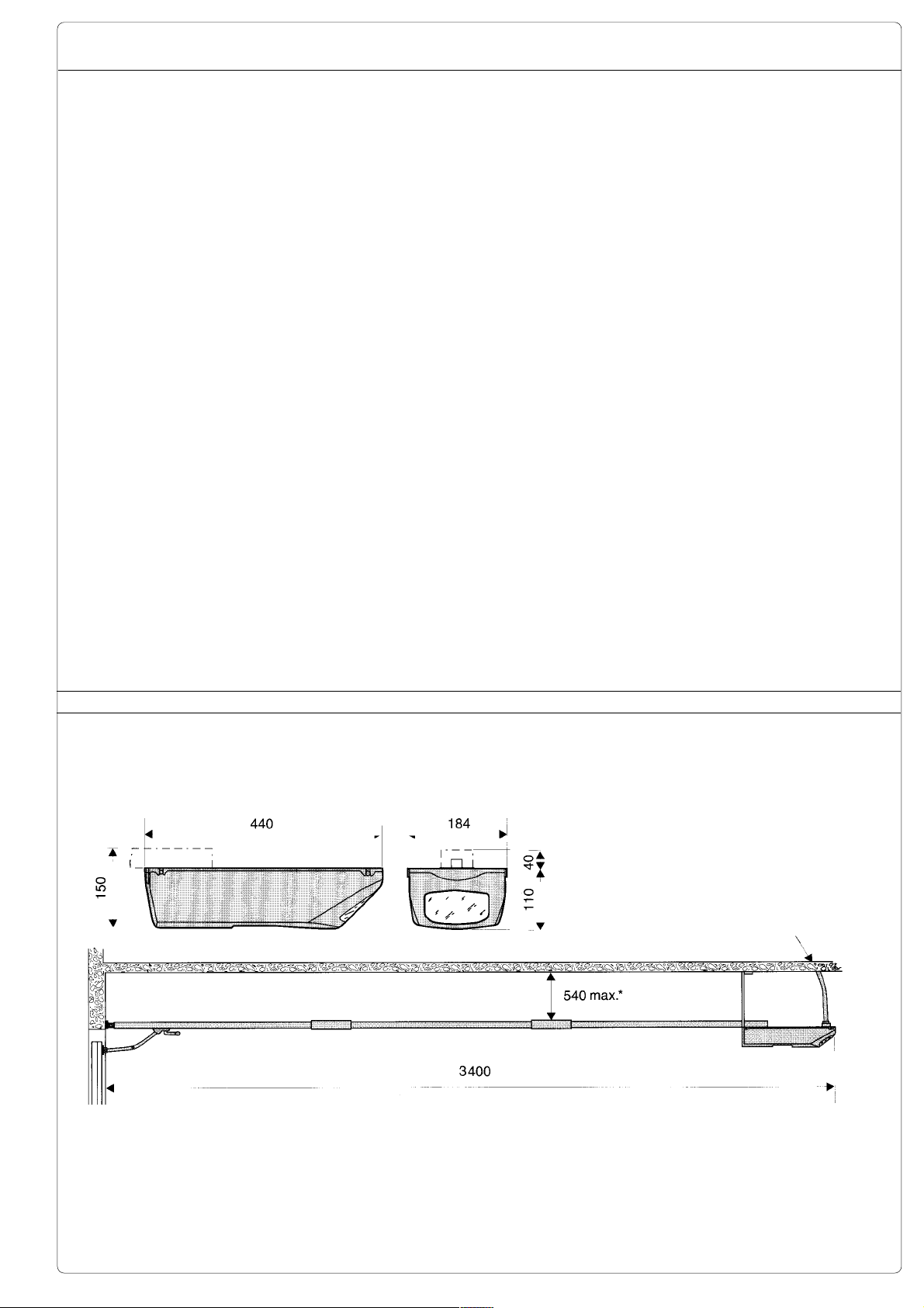
MISURE D'INGOMBRO -
EXTERNAL DIMENSIONS
- MEASURES D'ENCOMBRENT -
ABMESSUNGEN
2
* Per altezze superiori a tale valore, prevedere dei tiranti o staffe supplementari
For heights exceding 540 mm., it is necessary to use additional brackets or struts
Pour des hauteurs superieures a cette valeur, prevoir des tirants ou des etriers supplementaires
Bei Höhen, die obiges Maß überschreiten zusätzliche Schubstangen oder Bügel montieren
Para las alturas mayores que esta medida, se deben utilizar unos tirantes o soportes adicionales
- DIMENSIONES
Uscita cavi
Cable exit
Sortie cables
Netzkabeleingang
Salida de los cables
3
ACCESSORI DI COMPLETAMENTO -
ZUBEHOR -
ACCESSOIRES SUPPLIED -
ACCESORIOS DE COMPLETACION
ACCESSOIRES COMPLEMENTAIRES
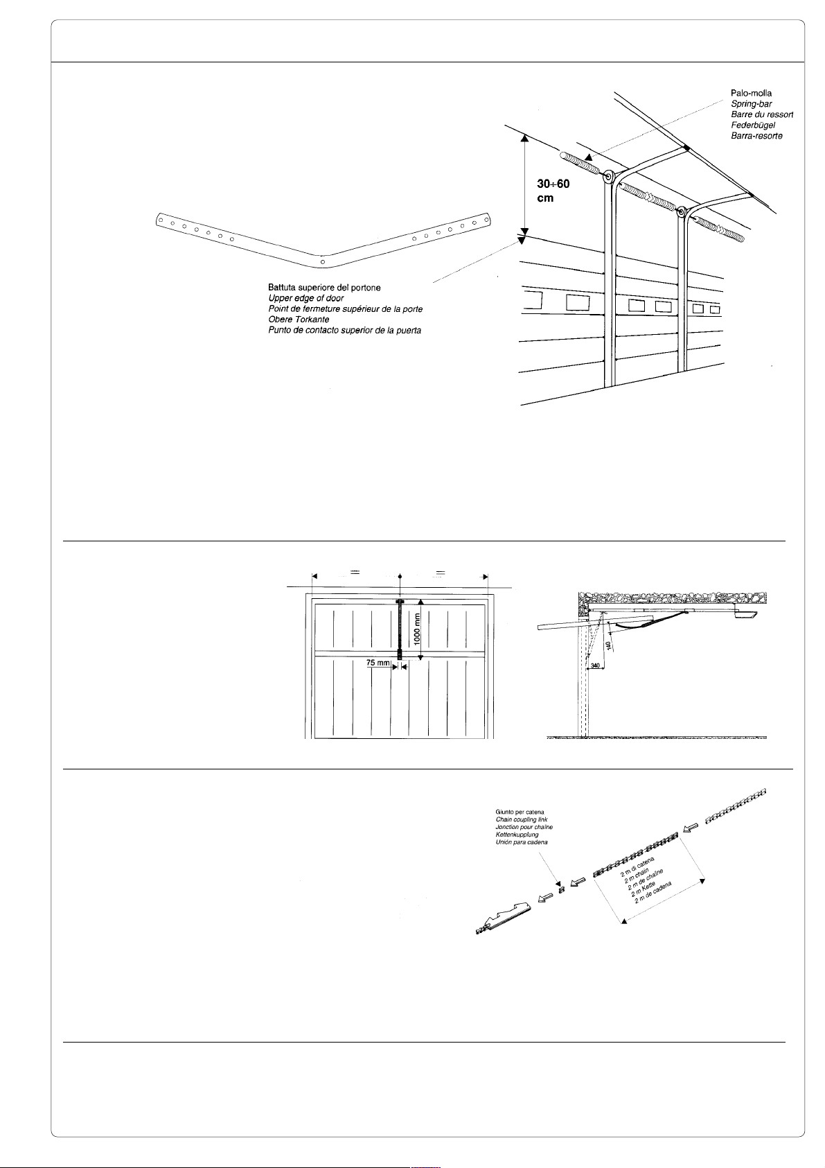
- V122: leva per porte sezionali A. Da applicare
quando la distanza fra il
palo-molla e la battuta
superiore del portone è
compresa fra 30 e 60 cm.
(pag 5).
- V201: sistema adattatore per porte basculanti C
a contrappesi (pag 5).
- V203: confezione completa di: 1 guida, 1 staffa
di giunzione, 1 giunto
per catena e 2 m. di catena per l’aumento della
corsa di 1 m. (pag 5).
- V122: bracket for sec-
tional doors A. Recommended when the distance between the springbar and the upper edge of
the door is between 30
and 60 cm. (page 5).
- V201: adaptor arm for
overhead doors C with
counterweight balancing
(page 5).
- V203: extension kit including 1 guide, 1 junction
bracket, 1 chain coupling
link and a 2 m. chain extension to increase the
movement of 1 m.
(page 5).
- V122: levier pour portes sectionnelles A. Celui-ci doit être appliqué
lorsque la distance entre
la barre du ressort et le
point de fermeture supé-
rieur de la porte est
comprise entre 30 et 60
cm (page 5).
- V201: système adaptateur pour portes basculantes C à contrepoids (page 5).
- V203: emballage comprenant : 1 guide, 1
étrier de jonction, 1
pièce de jonction pour
chaîne et 2 m de chaîne
pour une augmentation
de course de 1 m.
(page 5).
- V122: Hebel für Sektio-
naltor A. Der Hebel wird
bei Sektionaltoren, wenn
der Absland zwischen Federbügel und oberer
Torkante zwischen 30 und
60 cm liegt, angewendet.
(Seite 5).
- V201: Adaptersystem für
Schwingtore C mit Gegengewicht (Seite 5).
- V203: Kompletter Bausalz: 1 Laufschiene, 1
Verbindungsstück, 1 Kerenkupplung und 2 m
Kette zur Fahrwegverlängerung um 1 m
(Seite 5).
- V122: palanca para
puertas seccionales A.
Se debe aplicar cuando
la distancia entre la barra-resorte y el punto de
contacto superior de la
puerta es 30 a 60 cm
(pág 5).
- V201: sistema adaptador para puertas basculantes C por contrapesos (pág 5).
- V203: embalaje formado por: 1 guía, 1 soporte
de unión, 1 unión para
cadena y 2 m de cadena
para aumentar 1 m la carrera (pág 5).
A
B
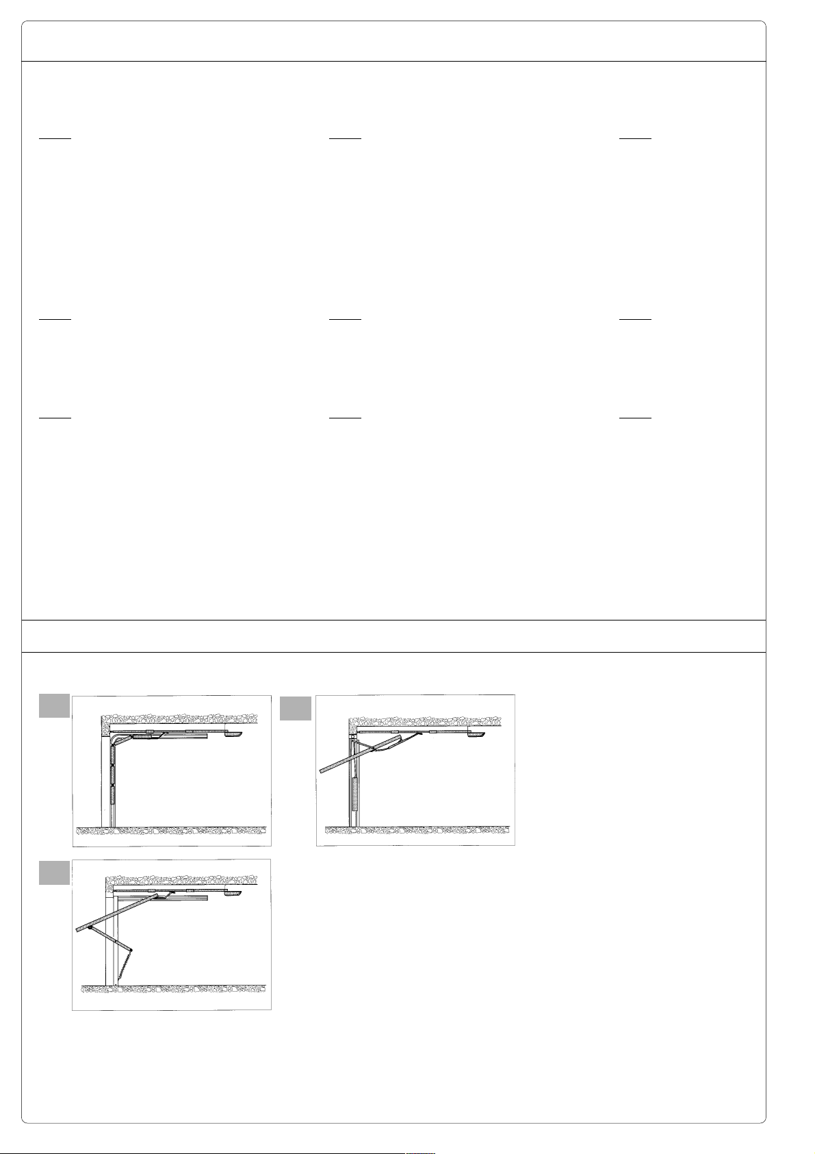
ESEMPI DI APPLICAZIONE -
INSTALLATIONSBEISPIELE
C
EXAMPLES OF APPLICATIONS
- EJEMPLOS DE APLICACIONES
A - Portone sezionale
Porte sectionnelle
Puerta seccional
B - Porta basculante a molle
Porte basculante à ressort
Feder-Schwingtor
Puerta basculante a muelle
- EXEMPLES D’APPLICATIONS
Sectional door
Sektionaltor
Spring-balanced overhead door
C - Porta basculante a contrappesi
Overhead door with counterweight balancing
Porte basculante à rail vertical
Schwingtor mit Gegengewichten
Puerta basculante por contrapesos
4
ACCESSORI DI COMPLETAMENTO -
V122V122
V122
V122V122
Leva per portoni sezionali
Lever for sectional doors
Levier pour portes à lattes
Hebel für Sektionaltore
Palanca para puertas seccionales
ZUBEHOR -
ACCESSOIRES SUPPLIED -
ACCESORIOS DE COMPLETACION
ACCESSOIRES COMPLEMENTAIRES
- Questa leva si applica
quando la distanza fra il
palo-molla e la battuta
superiore del portone è
compresa fra 30 e 60
cm.
V201V201
V201
V201V201
Braccio adattatore per porte
basculanti a contrappesi
Adaptor arm for overhead doors with
counterweights
Bras d'adaptation pour portes
basculantes à contrepoids
Adapterarm für Schwingtore mit
Gegengewichten
Brazo adaptador para puertas
basculantes a contrapesos
V203V203
V203
V203V203
Prolunga per l'aumento della corsa di 1 m.
Extension guide for 1 m. extension of movement
Rallonge pour une augmentation de course de 1 m
Verlängerungsstück zur Fahrwegverlängerung um 1 m
Pieza de prolongación para aumentar 1 m la carrera
-
This lever should be
fitted when the distance
between the spring-bar
and the upper edge of the
door is between 30 and 60
cm.
- On applique ce levier
lorsque la distance entre
la barre-ressort et le
point de fermeture
supérieur de la porte est
comprise entre 30 et
60 cm.
- Dieser Hebel wird
montiert, wenn der
Abstand zwischen
Federträger und oberem
Toranschlag zwischen 30
und 60 cm liegt.
- Esta palanca se debe
incorporar cuando la
distancia entre la
barra-resorte y el punto
de contacto superior de
la puerta es 30 a 60 cm.
- Da applicare nel caso
l'altezza della porta sia
compresa fra i 2,50 e i
3,50 metri.
PER ULTERIORI INDICAZIONI,
CONSULTARE I FOGLI TECNICI AL-
LEGATI ALLE CONFEZIONI DEGLI
ACCESSORI
- The extension guide
should be used if the
height of the door is
between 2.5 and 3.5
metres.
FOR
FURTHER DETAILS, REFER
THE TECHICAL DATA SHEETS
TO
WITH THE ACCESSOIRES
SUPPLIED
- A appliquer si la
hauteur de la porte est
comprise entre 2.50 et
3.50 mètres.
POUR D'AUTRES INDICATIONS,
CONSULTER LES FEUILLETES
TECHNIQUÉS
ACCESSOIRES
FOURNIS AVEC LES
5
- Der Bausatz wird bei
Torhöhen zwischen 2.50
und 3.50 m installiert.
W
EITERE INSTALLATIONSTIPS
SIE IN
FINDEN
Z
UBEHÖ RVERPACKUNG
BEIGELEGTEN
D
ATENBLÄTTERN
DEN DER
TECHNISCHEN
- Se debe incorporar
cuando la altura de la
puerta es 2.50 a 3.50
metros.
PARA MÀS INFORMACIONES,
VÉANSE LOS FOLLETOS TÉCNICOS
ADJUNTOS
LOS
A LOS EMBALAJES DE
ACCESORIOS
ASSEMBLAGGIO DEL GRUPPO -
ZUSAMMENBAU DES ANTRIEBS -
ASSEMBLING THE UNIT -
MONTAJE DEL CONJUNTO
ASSEMBLAGE DU GROUPE
1
Guida
Guide
Guide
Schiene
Guía
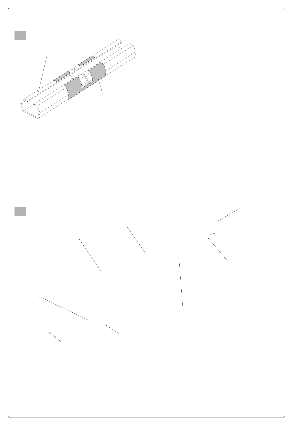
ATTENZIONE: Se l’altezza della porta è superiore ai limiti di impiego di
pag. 2, applicare l’accessorio V203, aggiungendo la guida e la staffa di
giunzione. Collegare i 2
m di catena aggiuntiva a
quella già assemblata
mediate il giunto per catena.
Staffa di giunzione
Junction bracket
Etrier de jonction
Verbindungsstück
Soporte de union
N.B. If the height of the
door is over the operating
limits at page 2, use the
V203 extension kit, adding
the supplementy guide
and junction bracket. Connect the 2 metre chain extension to the original
chain, using the chain
coupling link.
Predisporre il gruppo collegando le tre guide mediante le due
staffe di giunzione.
Connect the three guides sections using the two junction
brackets.
Préparer le groupe en assemblant le 3 guides à l'aide des 2
étriers de jonction.
Die drei Schienenteile mittels der beiden Verbindungsstücke
zusammensetzen.
Emplazar el grupo empalmando las 3 guías mediante los 2
soportes de uníon.
ATTENTION: Si la hauteur
de la porte est superiore
aux limits d’emploi à la
pag. 2, il faut appliquer
l’accessoire V203, en
ajoutant le guide et l’étrier
de jonction. Unir les 2 m
de chaîne supplémentaire
à celle déjà assemblée en
utilisant la pièce de jonc-
tion pour chaîne.
WICHTIG! Wäre die Torhöhe über dem Anwendungsgebiet (Seite 2),
muß der Zubehörsatz
V203 mit zusätzlicher
Schiene und Verbindungsstück montiert werden. Die 2 m lange Kette
mittels dei Kettenkupplung
mit der bereits montierten
Kette verbinden.
CUIDADO: Si la altura de
la puerta es major de los
limites de uso de la pág.
2, aplicar el accesorio
V203, incorporandoo la
guía y el soporte de
uníon. Empalmar los 2 m
de cadena adicional a la
que ya se ha montado,
por medio de la unión
para cadena.
2
Staffa “C”
Bracket “C”
Etrier “C”
Befestigungsbügel “C”
Soporte “C”
Attacco tendicatena
Chain tensioner coupling
Pièce de tension de la
chaine
Kettenspanneranschlüß
Empalme tensor de cadena
Vite di regolazione
Regulation screw
Vis de réglage
Regelschraube
Tornillo de ajuste
Leva
Arm
Levier
Hebel
Palanca
Guida
Guide
Guide
Schiene
Guía
Pattino
Sliding block
Patin
Gleitbacke
Patin
Catena
Chain
Chaîne
Kette
Cadena
Giunto
Chain coupling link
Pièce de jonction
Kupplung
Union
- Inserire la catena all’interno delle guide posizionando il giunto e il
pattino a circa metà della lunghezza totale delle
guide con l’attacco
tendicatena nella posizione illustrata.
- Insert the chain into the
guides, positioning the
chain coupling and the
sliding block at approximately the midway point
of the guides. The chain
tensioner coupling should
be positioned as shown in
the figure.
- Introduire la chaîne à
l’intérieur des guides en
positionnent la pièce de
jonction et le patin à une
distance correspondant
à environ la moitié de la
longueur totale des guides et en plaçant la
pièce de tension de la
chaîne de la manière
diquée dans la figure.
6
in-
- Die Kette in die Laufschiene einsetzen und
Kettenkupplung und Gleit
backe etwa in der Mitte
der Gesamt Länge der
Schienen plazieren. Der
Kettenspanneran-schluß
sollte gemäß der Abbildung liegen.
- Introducir la cadena en
las guias colocando la
unión y el patín en la mitad de la longitud total
de las guías, con el empalme tensor de cadena
en la posición indicada.

3
Innesti
Guide anchor slots
Eléments de fixation
Klemmen
Uniones
Collegare la catena al
pignone facendola sporgere leggermente dalle
guide e ancorare le guide alla base del
motoriduttore sugli appositi innesti.
4
Fit the chain to the pinion
and insert the guides into
the anchor slots on the
gear motor.
Rondella
Washer
Dado
Nut
Ecrou
Mutter
Tuerca
Rondelle
Unterlegschleibe
Arandela
Unir la chaîne au pignon
et fixer les guides à la
base du motoréducteur
sur les éléments de fixation appropriés.
Staffa “A”
Bracket “A”
Etrier “A”
Befestigungsbügel “A”
Soporte “A”
Die Kette so auf den Antriebsritzel spannen, und
die Schienen am
Getriebemotorgehäuse in
den ent sprechenden
Klemmen einrasten.
Enzalar la cadena al piñon y fijar las guías en
la base del motorreductor, en las uniones
especificas.
Guida
Guide
Guide
Schiene
Guía
- Inserire la staffa “A”
nell’attacco tendicatena
e regolare la tensione
della catena agendo sul
dado.
N.B.: la catena deve essere leggermente messa
in tensione.
- Fin bracket “A” to the
chain tensioner connector
and turn the nut to adjust
the tension of the chain.
N.B.: The chain must be
slightly taut.
Molla
Spring
Ressort
Feder
Resorte
- Introduire l’étrier “A”
dans la pièce de tension
de la chaîne et régler la
tension de la chaine en
agissant sur l’écrou.
N.B.: la chaîne doit être
légèrement tendue.
7
Vite di regolazione
Regulation screw
Vis de réglage
Regelschraube
Tornillo de ajuste
- Den Belestigungsbügel
“A” in den Kettenspannanschluß stecken und
die Kettenspannung mittels der Mutter einstellen.
Anmerkung: Die Kette
muß leicht gespannt sein.
- Introducir el soporte
“A” en el empalme
tensor de cadena y regular la tensión de la cadena actuando sobre la
tuerca.
N.B.: la cadena debe someterse ligeramente a
tensión.
Telaio della porta
Door frame
Châssis de la porte
Torrahmen
Bastídor de la puerta
5
Staffa “A”
Bracket “A”
Etrier “A”
Befestigungsbügel “A”
Soporte “A”
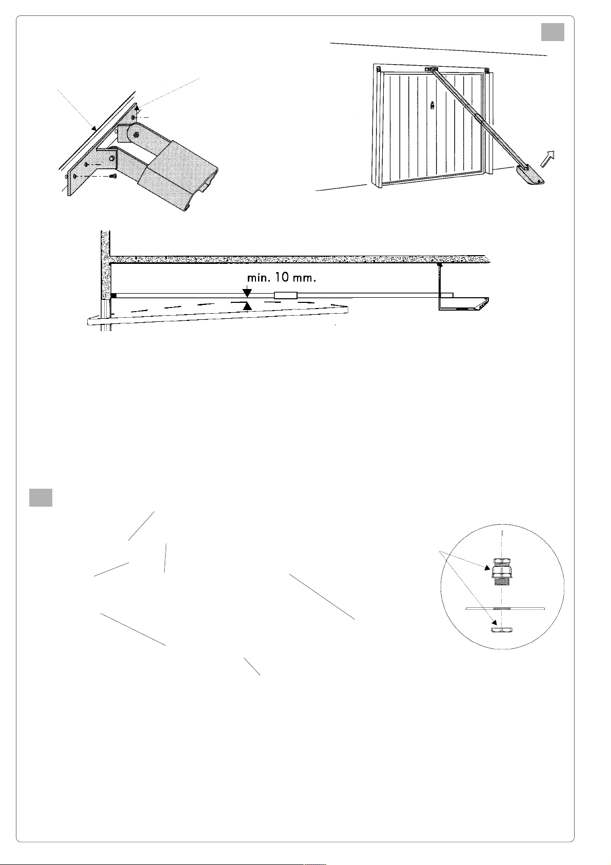
Fissare centralmente
(con viti o rivetti) la staffa “A” al telaio della porta (montaggio consigliato) o al muro, a circa 1020 mm. sopra il punto
massimo di scorrimento
dell’anta.
6
Staffe “B”
Brackets “B”
Etriers “B”
Befestigungsbügel “B”
Soportes “B”
Bolt or rivet bracket “A “ in
the Gen tre of the door
frame (recommended position) or to the wall itself,
about 10-20 mm above
the highest position
reached by the door during movement.
Angolari
Angle-brackets
Cornières
Winkeleisem
Escuadras
Fixer (à l’aide de vis ou
de rivets) l’étrier “A” sur
le châssis de la porte
(montage conseillé) ou
sur le mur, de façon à ce
que l’étrier soit positionné au centre, 10-20
mm au-dessus du point
supérieur de coulissement du vantail.
Coperchio
Cover
Couvercle
Haube
Tapa
Den Belestigungsbügel “A”
mitting am Torprolil (empfohlene Montage) oder an
der Decke mit Schrauben
bzw. Nieten befestigen, ca.
10-20 mm über dem
Torhöchstpunkl des Tores.
Pressacavo
Cable fairlead
Serre-câble
Kabelhülse
Abrazadera de cables
Foro per pressacavo
Hole for cable fairlead
Trou pour serre-câble
Kabelhülsenbohrung
Agujero para la
abrazadera
de cables
Fijar en el centro (por
medio de tornillos o remaches) el soporle “A”
en el bastidor de la puerta (montaje aconsejado)
o en la pared, a unos 1020 mm encima del punto
superior de deslizamiento de la hoja.
Togliere il coperchio e
applicare:
- il pressacavo in dotazione
- le staffe “B” al gruppo
e successivamente al
soffitto mediante gli
appositi angolari utilizzando viti e tasselli.
Remove the cover and lift:
- the cable fairlead supplied with the unit
- the “B” brackets to the
unit and then to the ceiling using the angle
brackets to be fixed with
some screws or bolts.
Enlever le couvercle et
appliquer:
- le serre-câble fourni
avec le matériel
- les étriers “B” sur le
groupe et puis au plafond en utilisant les
cornières avec de vis
ou de chevilles.
8
Deckel abnehmen und:
- mitgelieferte Kabelschelle und
- Bügel anbringen und
dann die Gruppe mit den
entsprechenden Winkeleisen mittels Schrauben
und Dübeln an der Dekke befestin-gen.
Quitar la tapa del motorreductor y aplicar:
- la abrazadera de cables
suministrada
- los soportes “B” en el
conjunto y sucesivamente en el tecio por
medio de las éscuadras utilizando los tornillos de expansión.
 Loading...