


SET |
Documentazione |
Tecnica |
|
S61 |
|
COMPLETE |
rev. 1.5 |
04/2001 |
|
©CAME |
|
U8700 |
CANCELLI |
AUTOMATICI |
|
119DS61 |
CANCELLI AUTOMATICI
CONFEZIONE COMPLETA PER L'AUTOMAZIONE DI CANCELLI PEDONALI E/O CARRABILI A 2 ANTE A BATTENTE DI LARGHEZZA MASSIMA FINO A 1.60 M PER ANTA CON MOTORIDUTTORE F500
COMPLETE SET FOR POWERING PEDESTRIAN AND/OR DRIVEWAY GATES HAVING TWO SWINGING GATE WINGS WITH MAXIMUM WIDTH OF 1.60 M EACH WITH F500 GEARMOTOR
SET COMPLET POUR L'AUTOMATISATION DE PORTAILS A BATTANT POUR PIETONS ET/OU VOITURES A DEUX VANTAUX AYANT UNE LARGEUR MAXIMALE DE 1.60 M CHACUN AVEC MOTORÉDUCTEUR F500
KOMPLETTES MONTAGESET FÜR DEN ANTRIEB VON ZWEIFLÜGELIGEN EINGANGSUND/ODER EINFAHRTSTOREN MIT EINER HÖCHSTBREITE VON 1.60 M PRO TORFLÜGEL MIT F500 GETRIEBEMOTOR
CONJUNTO COMPLETO PARA LA AUTOMATIZACION DE PUERTAS PEATONALES Y/O CARRILES A DOS HOJAS BATIENTES DE LONGITUD MAXIMA DE HASTA 1.60 M CADA HOJA CON MOTORREDUCTOR F500
1
7 1
8
2
5
3
|
|
|
RG58 |
|
|
|
|
|
2 x 1 |
* 2 x 1.5 |
|
|
|
|
|
|
2 x 1 |
|
|
|
|
|
|
|
|
|
|||
|
|
|
|
|
|
|
|
|
|
|
|
|
9 |
|
|
|
|
|
|
|
|
|
|
|
|
|
|
|
|
|
|
3x1,5 / 230V |
4 x 1 |
|
|
|
|
|
|
|
|
|
|
|
|
|
|
|
|
|
|
|
|
|
|
|
|
|
|
|
|
|
2 x 1 |
|
|
|
|
|
|
|
|
|
|
|
|
|
|
|
*2x1,5 |
|
|
|
|
|
|
|
|
|
|
|
|
|
2 x 1.5 |
|
|
4 |
|
|
|
|
|
|
|
|
|
|
|
|
|
|
|
|
|
|
|
|
|
|
|
|
|
Impianto tipo |
|
|
|
|
6 |
|
|
|
|
|
|
|
|
|
Standard installation |
|
|
|
|
|
|
|
|
|
|
|
|
|
|
Installation type |
|
4 |
|
|
|
|
|
|
|
|
|
|
|
|
Standard Montage |
|
|
|
|
|
|
|
|
|
|
|
|
|
|
|
|
|
|
|
|
|
|
|
|
|
|
|
|
|
Instalación tipo |
|
|
|
|
|
|
|
|
|
|
|
|
|
|
|
|
|
|
|
* 2 x 1,5 |
|
|
|
|
|
|
|
|
Cavi di alimentazione motori: |
|
Power wires to motor: |
Câbles d'alimentation moteur: |
Antriebsmotor-Verbindungskabel: |
Cables de alimentación motores: |
||||||||
|
|
2 x 1.5 mm2 fino a 20 m |
|
2 x 1.5 mm2 up to 20 m |
|
|
2 x 1.5 mm2 jusqu'à 20 m |
|
|
|
2 x 1.5 mm2 bis 20 m |
|
|
2 x 1.5 mm2 hasta 20 m |
|
|
2 x 2.5 mm2 fino a 30 m |
|
2 x 2.5 mm2 up to 30 m |
|
|
2 x 2.5 mm2 jusqu'à 30 m |
|
|
|
2 x 2.5 mm2 bis 30 m |
|
|
2 x 2.5 " " 30 m |
|
|
Composizione set: |
|
Set composition: |
|
|
Composition set: |
Das Montageset enthält: |
|
|
Composición set: |
|||
1 |
- Gruppo |
1 - |
Gear motor unit |
1 |
- Groupe |
1 |
- |
Antriebsmotor |
1 |
- Conjunto |
||||
|
|
motoriduttore |
2 - |
Control panel |
|
|
motoréducteur |
2 |
- |
Steuergerät |
|
|
motorreductores |
|
2 |
- Quadro comando |
3 - |
Radio receiver |
2 |
- Armoire de |
3 |
- |
Funkempfänger |
2 |
- Cuadro de mando |
||||
3 |
- |
Ricevitore radio |
4 - |
Photocells |
|
|
commande |
4 |
- |
Photozellen |
3 |
- |
Radioreceptor |
|
4 |
- |
Fotocellule |
5 - |
Protruding switch |
3 |
- Récepteur radio |
5 |
- |
Außenmontage- |
4 |
- |
Fotocélules |
||
5 |
- |
Selettore esterno |
6 - |
Electric lock |
4 |
- |
Photocellule |
|
|
Schalter |
5 |
- |
Selector exterior |
|
6 |
- |
Elettroserratura |
7 - |
Flasher |
5 |
- |
Sélecteur externe |
6 |
- |
Elektroschloß |
6 |
- |
Cerradura eléctrica |
|
7 |
- Lampeggiatore |
8 - |
Antenna |
6 |
- |
Serrure électrique |
7 |
- |
Blinkleuchte |
7 |
- Lámpara |
|||
8 |
- Antenna |
9 - |
transmitter |
7 |
- |
Clignotant |
8 |
- |
Antenne |
8 |
- Antena |
|||
9 |
- |
trasmettitore |
|
|
8 |
- Antenne |
9 |
- |
Funksender |
9 |
- |
Trasmisor |
||
|
|
|
|
|
9 |
- Emetteur |
|
|
|
|
|
|
|
|
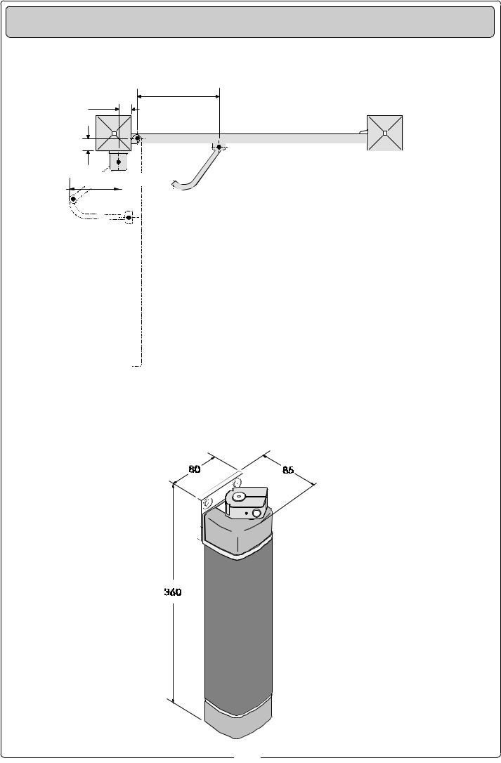
ASSI E INGOMBRI - CENTRE LINES AND EXTERNAL DIMENSIONS - AXES ET ENCOMBREMENTS
ACHSEN & ABMESSUNGEN - EJES Y DIMENSIONES MÁXIMAS
B= 350
A
C


 E
E


|
|
|
|
|
|
|
|
|
|
|
|
|
|
|
|
|
|
|
|
|
|
|
|
|
|
Larghezza anta |
Peso anta |
|
|
|
|
|
|
|
|
|
|
|
|
|
|
|
|
|
|
|
|
|
|
|
|
|
|
|
Width of gate wing |
Weight of gate wing |
|
|
|
|
|
|
|
|
|
|
|
|
|
|
|
|
|
|
|
|
|
|
|
|
|
|
|
Largeur du vantail |
Poids du vantail |
|
|
|
|
|
|
|
|
|
|
|
|
|
|
|
|
|
|
|
|
|
|
|
|
|
|
|
Torbreite |
Torgewicht |
|
|
|
|
|
|
|
|
|
|
|
|
|
|
|
|
|
|
|
|
|
|
|
|
|
|
|
Ancho hoja |
Peso hoja |
|
|
|
|
|
|
|
|
|
|
|
|
|
|
|
|
|
|
|
|
|
|
|
|
|
|
|
m. |
Kg. |
|
i = 230 mm. max |
||||||||||||||||||||||||||||
|
|
|
|
|
|
|
|
|
|
|
|
|
|
|
|
|
|
|
|
|
|
|
|
|
|
|
||
|
|
|
|
|
|
|
|
|
|
|
|
|
|
|
|
|
|
|
|
|
|
|
|
|
0,80 |
150 |
||
con apertura a 90° |
|
|
|
|
|
|
|
|
|
|
|
|
|
|
|
|||||||||||||
|
|
|
|
|
|
|
|
|
|
|
|
|
|
|
|
|
|
|
|
|
|
|
|
|
|
|
||
|
|
|
|
|
|
|
|
|
|
|
|
|
|
|
|
|
|
|
|
|
|
|
|
|
|
|
||
with 90° opening angle |
|
|
|
|
|
|
|
|
|
|
|
|
|
|
|
1,20 |
125 |
|||||||||||
avec ouverture à 90° |
|
|
|
|
|
|
|
|
|
|
|
|
|
|
|
|
|
|
|
|
|
|
|
|
|
|
|
|
mit 90°-Öffnungwinkel |
|
|
|
|
|
|
|
|
|
|
|
|
|
|
|
|
|
|
|
|
|
|
|
|
|
1,60 |
100 |
|
con apertura a 90° |
|
|
|
|
|
|
|
|
|
|
|
|
|
|
|
|||||||||||||
|
|
|
|
|
|
|
|
|
|
|
|
|
|
|
|
|
|
|
|
|
|
|
|
|
|
|
||
|
|
|
|
|
|
|
|
|
|
|
|
|
|
|
|
|
|
|
|
|
|
|
|
|
|
A |
C |
|
|
|
|
|
|
|
|
|
|
|
|
|
|
|
|
|
|
|
|
|
|
|
|
|
|
|
|||
|
|
|
|
|
|
|
|
|
|
|
|
|
|
|
|
|
|
|||||||||||
|
|
|
|
|
|
|
|
|
|
|
|
|
|
|
|
40÷150 |
0÷150 |
|||||||||||
|
|
|
|
|
|
|
|
|
|
|
|
|
|
|
|
|
|
|
|
|
|
|
|
|
|
|
|
|
|
|
|
|
|
|
|
|
|
|
|
|
|
|
|
|
|
|
|
|
|
|
|
|
|
|
|
|
|
|
|
|
|
|
|
|
|
|
|
|
|
|
|
|
|
|
|
|
|
|
|
|
|
|
|
|
|
|
|
|
|
|
|
|
|
|
|
|
|
|
|
|
|
|
|
|
|
|
|
|
|
|
|
|
|
|
|
|
|
|
|
|
|
|
|
|
|
|
|
|
|
|
|
|
|
|
|
|
|
|
|
|
|
|
|
|
|
|
|
|
|
|
|
|
|
|
|
|
|
|
|
|
|
|
|
|
|
|
|
|
|
|
|
|
|
|
|
|
|
|
|
|
|
|
|
|
|
|
|
|
|
|
|
|
|
|
|
|
|
|
|
|
|
|
|
|
|
|
|
|
|
|
|
|
|
|
|
|
|
|
|
|
|
|
|
|
|
|
|
|
|
|
|
|
|
|
|
|
|
|
|
|
|
|
|
|
|
|
|
|
|
|
|
|
|
|
|
|
|
|
|
|
|
|
|
|
|
|
|
|
|
|
|
|
|
|
|
|
|
|
|
|
|
|
|
|
|
|
|
|
|
2
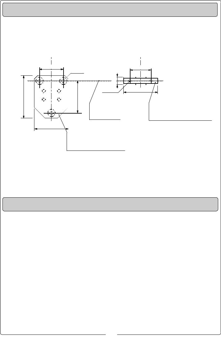
ASSI E INGOMBRI - CENTRE LINES AND EXTERNAL DIMENSIONS - AXES ET ENCOMBREMENTS
ACHSEN & ABMESSUNGEN - EJES Y DIMENSIONES MÁXIMAS
56 |
3 x ø 8,5 |
50 |
|
|
|
|
17,5 |
|
|
2 x ø 6,5 |
80 |
100 |
76 |
|
Asse comune |
Staffa di aggancio braccio snodato |
Common centre line |
Bracket articulated arm |
Axe commun |
Etriere de fixation du bras articulés |
Gemeinsame Achse |
Armbefestigungs-Bügel |
Eje común |
Estribo de enganche brazo articolados |
80
Flangia attacco motoriduttore
Gear motor mounting flange
Bride de raccord du motoréducteur
Getriebemotorbefestigungs-Flansch
Brida anclaje motorreductor
CARATTERISTICHE TECNICHE - TECHNICAL CHARACTERISTICS - CARACTERISTIQUES TECHNIQUES
TECHNISCHE DATEN - CARACTERISTICAS TECNICAS
MOTORIDUTTORE |
GRADO DI |
PESO |
ALIMENTAZIONE |
CORRENTE |
POTENZA |
INTERMITTENZA |
COPPIA |
RAPPORTO DI |
|
MASSIMA |
|||||||||
PROTEZIONE |
MASSIMA |
LAVORO |
MASSIMA |
RIDUZIONE |
|||||
|
|
|
ASSORBITA |
||||||
|
|
|
|
|
|
|
|
||
|
PROTECTION |
|
|
MAXIMUM |
MAXIMUM |
|
MAXIMUM |
REDUCTION |
|
GEARMOTOR |
WEIGHT |
POWER SUPPLY |
POWER |
DUTY CICLE |
|||||
RATING |
CURRENT |
TORQUE |
RATIO |
||||||
|
|
|
CONSUMPTION |
|
|||||
|
|
|
|
|
|
|
|
||
MOTORÉDUCTEUR |
DEGRÉ DE |
POIDS |
ALIMENTATION |
COURANT |
PUISSANCE |
INTERMITTENCE |
COUPLE |
RAPPORT DE |
|
MAXIMALE |
|||||||||
PROTECTION |
MAXIMALE |
DE TRAVAIL |
MAXIMALE |
REDUCTION |
|||||
|
|
|
ABSORBEE |
||||||
|
|
|
|
|
|
|
|
||
GETRIEBEMOTOR |
SCHUTZGRAD |
GEWICHT |
STROM_ |
MAXIMAL_ |
HÖCHST_ |
EINSCHALTDAUER |
HÖCHST_ |
UNTERSETZUNGS_ |
|
LEISTUNG_ |
|||||||||
VERSORGUNG |
STROM |
DREHMOMENT |
VERHÄLTNIS |
||||||
|
|
|
SAUFNAHME |
|
|||||
|
|
|
|
|
|
|
|
||
MOTORREDUCTOR |
GRADO DE |
PESO |
ALIMENTACION |
CORRIENTE |
POTENCIA |
INTERMITENCIA |
PAREJA |
RELACION DE |
|
MAXIMA |
MOTOR |
||||||||
PROTECCION |
MAXIMA |
TRABAJO |
REDUCCION |
||||||
|
|
|
ABSORBIDA |
MAXIMA |
|||||
|
|
|
|
|
|
|
|||
|
|
|
|
|
|
|
|
|
|
F500 |
IP 54 |
2,5 kg. |
24 V d.c |
2 A |
48 W |
50 % |
10 daNm |
1/531 |
|
|
|
|
|
|
|
|
|
|
3

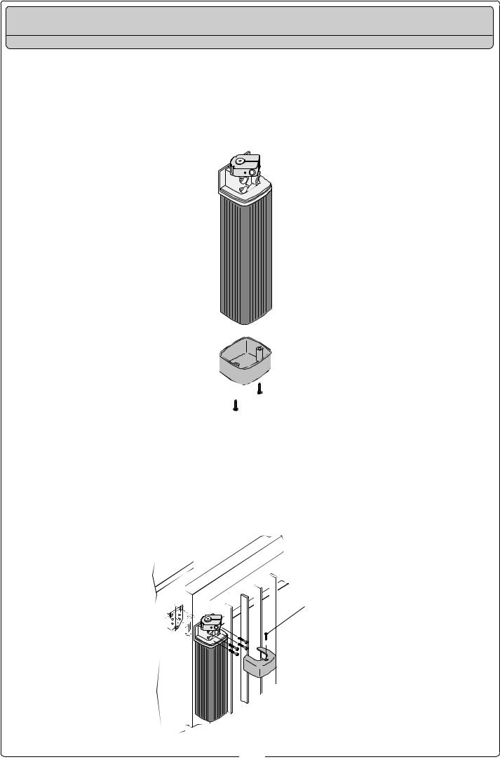
ISTRUZIONI DI MONTAGGIO | ASSEMBLY INSTRUCTIONS | INSTRUCTIONS POUR LE MONTAGE
MONTAGEANLEITUNG | INSTRUCCIONES DE MONTAJE
Descrizione fasi - Steps description - Description des phases - Reschreibung der Montagevorgänge - Descripción fases
1 Tracciare gli assi e gli ingombri dell’insieme tenendo conto degli schemi alle pagg. 2 e 3, quindi fissare la flangia di ancoraggio del motoriduttore al
muro o al pilastro e, per il motoriduttore F 500, il supporto di ancoraggio al cancello.
1 Trace the centre lines and external dimensions of the entire assembly in accordance with the diagrams on pages 2 and 3.
Next, mount the flange for the gear motor on the wall or pillar, and mount the anchor block for gear motor F500 on the gate.
1 Tracer les axes et les encombres de l’ensemble en se référant aux schémas de page 2 et 3, puis fixer la bride du motoréducteur au mur ou au pilier. Pour le motoréducteur F500, fixer le support de fixation au portail.
1 Die Achsen und Außenabmessungen der Antriebseinheit unter Berücksichtigung der schematischen Dar-stellungen auf Seite 2 und 3 aufreißen und dann den Getriebe- motor-Flansch an der Wand oder am Pfosten befestigen und, bei Verwedung des Getriebemotor F500, die entsprechende Befestigungsvorrichtung am Tor anbringen.
1 Trazar los ejes y las dimensiones del conjunto tenendo en cuenta los esquemas de pág. 2 y 3, posteriormente fijar la brida del motorreductor a la pared o al pilar y, para el motorreductor F500, el soporte de enclje a la puerta.
2 Assemblare il braccio snodato unendo i due semibracci con l’apposita bullo-neria.
2 Use the hardware provided with the unit to join the two halves of the articulated arm together.
2 Assembler le bras articulé en reliant les deux demi-bras avec la boulonnerie prèvue à cet effet.
2 Die beiden GelenKarmhälften mit den mitgelieferten Schrauben zusammenfügen
2 Ensamblar el brazo articulado uniendo los semi-brazos con los pernos correspondientes
4
ISTRUZIONI DI MONTAGGIO | ASSEMBLY INSTRUCTIONS | INSTRUCTIONS POUR LE MONTAGE
MONTAGEANLEITUNG | INSTRUCCIONES DE MONTAJE
Descrizione fasi - Steps description - Description des phases - Reschreibung der Montagevorgänge - Descripción fases
3 Togliere la calotta inferiore dal motoridut-tore.
3 Remove the cover at the bottom of the gear motor.
3 Enlever les carter inférieur du motoréductéur.
3 Die untere Getriebe- |
3 Desplazar el |
motor- |
casque-te inferior de |
Schutzabdeckung |
la puerta. |
entfernen. |
|
4 Fissare il moto- |
4 Using the four screws |
4 Fixer le |
riduttore alla flangia |
provided with the unit, |
motoréducteur à la |
mediante le quattro |
install the gear motor on |
bride à l’aide des |
viti in dotazione. |
the flange. |
quatre vis fournies. |
- Fissare la calotta |
- Fix the upper cap. |
- Fixer la calotte supé- |
superiore. |
|
rieure. |
4 Den Getriebemotor mit den vier zum Lieferumfang gehörenden Schrauben am Flansch befestigen.
-Die obere Gehäusehälfte Befestigen.
4 Fijar el motorreductor a la brida mediante los quatro tor-nillos suministrados.
- Fije la tapa superior.
ø 3,5 x 9,5
5

ISTRUZIONI DI MONTAGGIO | ASSEMBLY INSTRUCTIONS | INSTRUCTIONS POUR LE MONTAGE
MONTAGEANLEITUNG | INSTRUCCIONES DE MONTAJE
Descrizione fasi - Steps description - Description des phases - Reschreibung der Montagevorgänge - Descripción fases
5 Assemblare il braccio snodato (B) alla boccola intermedia solidale all’albero del motoriduttore;
-Fissare la staffa sul cancello con l’apposita bulloneria;
-Eseguire il collegamento elettrico, dare tensione al motoriduttore in chiusura e fissare il braccio tramite il grano M6 (C);
-Fissare la calotta inferiore.
5 Assemble the articulated arm (B) onto the intermediate bush which is all in one with the ratiomotor shaft;
-Using the hardware provided with the unit, install the bracket on the gate;
-Make the electrical connection, supply voltage to the ratiomotor during closure and secure the arm with the M6 (C) grub screw;
B
5 Assembler le bras articulé (B) à la douille intermédiaire solidaire de l’arbre du motoréducteur;
-Fixer l’étrier sur le portail avec la boulon-nerie prévue à cet effet ;
-Effectuer le branchement électrique, donner de la tension au motoréducteur en fermeture et fixer le bras à l’aide du boulon sans tête M6 (C);
-Fixer la calotte inférieure.
5 Den Gelenkarm (B) an der mittleren Buchse anbringen, die fest mit der Welle vom Getriebemotor verbunden ist.
-Den Bügel mit den ents-prechenden Schrauben am Tor befestigen.
-Den Stromanschluß durchführen, den Strom am Getriebemotor beim Schließen einschalten und den Arm mit dem Zapfen M6 (C) befestigen.
-Die untere Gehäusehälfte Befestigen.
5 Ensamble el brazo articulado (B) al casquillo intermedio integrado con el árbol del motorreductor;
-Fijar el estribo a la puerta con los tornillos correspondientes;
-Haga la conexión eléctrica, ponga bajo tensión el motorreductor durante el cierre y fije el brazo con el pasador M6 (C);
-Fije la tapa inferior.
C
 ø 3,9 x 13
6 completare l’installazione fissando il coperchietto superiore con il relativo OR.
6 Complete installation by mounting the upper cover with its OR gasket.
6 Terminer l’instal-lation |
6 Die Installation |
en fixant le cou-vercle |
beenden und die |
supérieur avec le joint |
obere Abdeckung mit |
torique correspon-dant. |
entsprechender Rund- |
|
gummidichtung befe- |
|
stigen. |
6 Completar la instalación fijando la tapa superior con el corre-spondiente OR.
OR
6
 Loading...