


SERIES R ACCESSORIES
MAGNETIC LOOP
CONTROL DEVICE
SMA2
English EN
SERIES R ACCESSORIES
MAGNETIC LOOP
CONTROL DEVICE
SMA2
English EN
ENGLISH
ENGLISH
1. DESCRIPTION |
|
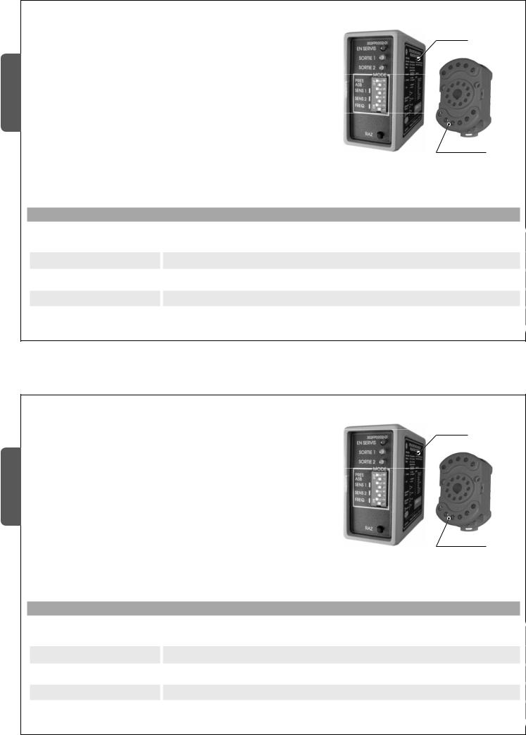
The 1 channel SMA sensor is a vehicle detector using electromagnetic |
Sensor |
loops. It is fitted with a microprocessor and has been designed for |
|
access and traffic flow controls |
|
The operating principle involves measuring the inductance variation in |
|
the magnetic loop caused when a vehicle passes over it. |
|
Inside the sensor, the measuring circuits for the two channels are |
|
multiplied to limit oscillations and interference that could be formed |
|
between the magnetic loops. |
|
SMA is complete with an 11-pin support/terminal block for connection |
|
to the loops and the 12 or 24 Vac/dc power supply. |
Support |
|
2. TECHNICAL FEATURES
|
ELECTRIC SPECIFICATIONS |
|
|
Supply voltage |
12/24 V ac/dc |
Current draw |
20 mA max |
Outlet relays |
Max capacity: 5 A at 230 Vac - Closed contact |
Magnetic loop inductance |
Between 20 and 1000 μH |
The data and information reported in this installation manual are susceptible to change at any time and without obligation on CAME cancelli automatici s.p.a. to notify users.
1. DESCRIPTION |
|
The 1 channel SMA sensor is a vehicle detector using electromagnetic |
Sensor |
loops. It is fitted with a microprocessor and has been designed for |
|
access and traffic flow controls |
|
The operating principle involves measuring the inductance variation in |
|
the magnetic loop caused when a vehicle passes over it. |
|
Inside the sensor, the measuring circuits for the two channels are |
|
multiplied to limit oscillations and interference that could be formed |
|
between the magnetic loops. |
|
SMA is complete with an 11-pin support/terminal block for connection |
|
to the loops and the 12 or 24 Vac/dc power supply. |
Support |
|
2. TECHNICAL FEATURES
|
ELECTRIC SPECIFICATIONS |
|
|
Supply voltage |
12/24 V ac/dc |
Current draw |
20 mA max |
Outlet relays |
Max capacity: 5 A at 230 Vac - Closed contact |
Magnetic loop inductance |
Between 20 and 1000 μH |
The data and information reported in this installation manual are susceptible to change at any time and without obligation on CAME cancelli automatici s.p.a. to notify users.
Pag. 2 - Manual code: 119RV04 ver. 0.1 03/2009 © CAME cancelli automatici s.p.a.
Pag. 2 - Manual code: 119RV04 ver. 0.1 03/2009 © CAME cancelli automatici s.p.a.

Pag. 3 - Manual code: 119RV04 ver. 0.1 03/2009 © CAME cancelli automatici s.p.a.
|
MECHANICAL SPECIFICATIONS |
|
|
|
|
Materials |
ABS plastic casing |
|
Fastenings |
Pressure sensor on the connector; connector mounted on DIN guides or screw in place |
|
Measurements LxHxP |
42 x 78 x 103 mm (sensor + connector) |
|
Weight |
230 g |
|
Operating temperature |
-40 / +70 °C |
|
Protection rating |
IP30 |
|
|
|
|
|
FUNCTIONAL SPECIFICATIONS |
|
|
4 ranges, selected through 2 dipswitches: |
|
|
- High sensitivity: 0.02%, L/L |
|
Sensitivity |
- Medium-high sensitivity: 0.05%, L/L |
|
|
- Medium-low sensitivity: 0.10% L/L |
|
|
- Low sensitivity: 0.50% L/L |
|
Working frequency |
High or low frequency, selected from a dipswitch; the frequency level depends on the size of the |
|
magnetic loop |
||
|
||
Output impulse length |
200 ms |
|
Response time |
100 ms |
|
Visual indicators |
- 1 red power on led |
|
- 2 green leds for sensor activities |
||
|
||
Relay outputs |
2 “presence” mode outputs |
The data and information reported in this installation manual are susceptible to change at any time and without obligation on CAME cancelli automatici s.p.a. to notify users.
ENGLISH
ENGLISH
ENGLISH
3.INSTALLING THE MAGNETIC LOOPS
3.1.Operating principles
The inductive loop sensor detects the presence of a vehicle on the surface marked out by a cabled loop, formed of 2 or more runs of leads beneath the road surface.
There are various solutions to prevent this:
-use different frequencies for each magnetic loop.
-keep the two groups of loops at least 2 meters away from each other.
When a vehicle goes over the loop the relative inductance measured by |
3.2.2. Interference caused by metal masses |
|
the sensor is reduced. |
||
|
This detection activates a relay and its contacts are used to guide the external devices.
The magnetic loop and the loop tail must be formed of a simple isolated lead, without any connections, in multithread copper, with a minimum section of 1.5 mm2 (16 AWG).
It is not advisable to make connections to the magnetic loop or to the power pack. However, if it is unavoidable they must be welded and isolated in a waterproof case.
This is very important to guarantee long lasting detection reliability.
3.2.Operating limits
3.2.1.Use of adjacent SMA sensors
When the magnetic loops are too close to each other, the respective magnetic fi elds could overlap and disturb the detection or damage the sensors.
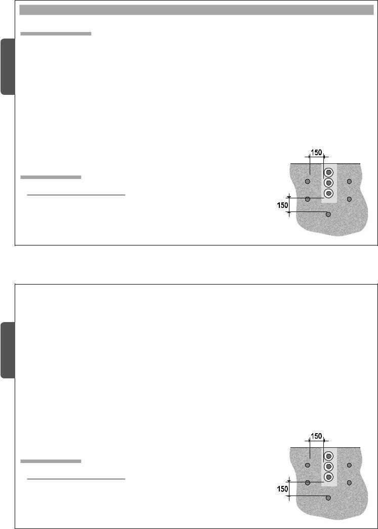
If there is any metal under the loops, especially if they are laid in reinforced concrete, it reduces the impedance and consequently the sensitivity of the sensor.
To compensate this reduction, two turns can be added to the detection loop.
Otherwise provide a minimum space of 150 mm between the magnetic loop and the reinforcing.
If the loop tail is channelled
with other cables, ensure that they are screened.
Clean and dry the cable duct before laying the cable.
The data and information reported in this installation manual are susceptible to change at any time and without obligation on CAME cancelli automatici s.p.a. to notify users.
|
3. INSTALLING THE MAGNETIC LOOPS |
|
|
|
||
|
3.1. Operating principles |
There are various solutions to prevent this: |
||||
|
|
|
- use different frequencies for each magnetic loop. |
|||
The inductive loop sensor detects the presence of a vehicle on the |
||||||
- keep the two groups of loops at least 2 meters away from each |
||||||
surface marked out by a cabled loop, formed of 2 or more runs of leads |
other. |
|||||
beneath the road surface. |
|
|
|
|||
When a vehicle goes over the loop the relative inductance measured by |
|
3.2.2. Interference caused by metal masses |
||||
the sensor is reduced. |
|
|||||
|
|
|
||||
This detection activates a relay and its contacts are used to guide the external devices.
The magnetic loop and the loop tail must be formed of a simple isolated lead, without any connections, in multithread copper, with a minimum section of 1.5 mm2 (16 AWG).
It is not advisable to make connections to the magnetic loop or to the power pack. However, if it is unavoidable they must be welded and isolated in a waterproof case.
This is very important to guarantee long lasting detection reliability.
3.2.Operating limits
3.2.1.Use of adjacent SMA sensors
When the magnetic loops are too close to each other, the respective magnetic fi elds could overlap and disturb the detection or damage the sensors.
If there is any metal under the loops, especially if they are laid in reinforced concrete, it reduces the impedance and consequently the sensitivity of the sensor.
To compensate this reduction, two turns can be added to the detection loop.
Otherwise provide a minimum space of 150 mm between the magnetic loop and the reinforcing.
If the loop tail is channelled
with other cables, ensure that they are screened.
Clean and dry the cable duct before laying the cable.
The data and information reported in this installation manual are susceptible to change at any time and without obligation on CAME cancelli automatici s.p.a. to notify users.
Pag. 4 - Manual code: 119RV04 ver. 0.1 03/2009 © CAME cancelli automatici s.p.a.
Pag. 4 - Manual code: 119RV04 ver. 0.1 03/2009 © CAME cancelli automatici s.p.a.
 Loading...