


TROPHY CAM™
I N S T R U C T I O N M A N U A L
N o t i c e D ’ u t i l i s a t i o n
Model/Modèle: 119437C / 119447C / 119476C / 119477C
Lit# 98-2294 / 07-12
Visit the Trophy Cam community website today, where you can:
•seemoreinformationaboutthecapabilitiesandapplicationsoftheBushnellTrophyCams
•discuss your Trophy Cam experiences with other users, share tips, belong to this new worldwidecommunity
•discoveranimalsfromallovertheworld
•accessafreeservicetomanageyourTrophyCamphotos/videosonlineandhostyourphotos (videosarehostedonYouTube)
www.bushnell.com/trophycam
Rejoignez la communauté Trophy Cam sur www.trophycam.fr pour :
•Trouverdesinformationssurl’utilisationetlescapacitésdevotreTrophyCam
•Partager vos expériences, vos conseils et astuces avec les autres utilisateurs de la communautémondialeTrophyCam
•Découvrirdesanimauxdumondeentier
•Accéder à un service internet gratuit pour gérer et publier les photos et vidéos prises avec votreTrophyCam(vidéoshébergéessurYouTube)
www.trophycam.fr

TABLE OF CONTENTS / TABLE DES MATIÈRES |
PAGE |
ENGLISH |
4-40 |
Français |
41-81 |
3
IMPORTANT NOTE
Congratulations on your purchase of one of the best trail cameras on the market! Bushnell is very proud of this little unit and we are sure you will be pleased with it as well. We appreciate your business and want to earn your trust. Please refer to the notes below and the instructions in this manual to ensure that you are completely satisfied with this product.
If your Bushnell Trophy Cam does not seem to be functioning properly or if you are having photo/video quality issues, please check the Troubleshooting/FAQ section on pages 33-37.
Problems are often due to something simple that was overlooked, or require only changing one setting to solve.
If your problem continues after trying the solutions in the Troubleshooting/FAQ section, please call Bushnell Customer Service at (800) 423-3537. In Canada, call (800) 361-5702.
Bushnell recommends using a full set of Energizer® Lithium AA batteries (8 or 12, depending on the model) in these Trophy Cam models to obtain maximum battery life
Do not mix old and new batteries
Do not mix battery types-use ALL lithium or ALL alkaline
Bushnell recommends using SanDisk® SD and SDHC Cards (up to 32GB capacity, Ultra® or Extreme® series for HD video) in these Trophy Cam models
4
INTRODUCTION
About the Trophy Cam
The Bushnell Trophy Cam is a digital scouting camera. It can be triggered by any movement of game in a location, detected by a highly sensitive Passive Infra-Red (PIR) motion sensor, and then take high quality pictures (up to 8MP still photos), or video clips.
The Trophy Cam consumes very little power (less than 0.2 mA) in a standby (surveillance) state. This means it can deliver up to six months standby operation time when the device is powered by the full capacity of AA alkaline batteries, and up to twelve months utilizing lithium AA batteries. Once motion in the monitored area is detected, the digital camera unit will be triggered at once (typically within one second) and then automatically take photos or videos according to previously programmed settings. The Trophy Cam is equipped with built-in infrared LEDs (“black” IR LEDs on models 119476/119477) that function as a flash, so that it delivers clear photos or videos (in black & white) even in the dark, and it can take color photos or videos under sufficient daylight. The Trophy Cam is designed for outdoor use and is resistant against water and snow.
Your trail camera is one of the latest generation of Bushnell Trophy Cams, and includes many new or improved features, including:
•Auto PIR Sensitivity-the camera monitors ambient temperature conditions and automatically adjusts the sensor/trigger signal to be more sensitive to slight variations in temperature on hot days, less sensitive on cold days.
•Hyper NightVision-The IR LED Flash array now has increased range, brighter output and better coverage for improved nighttime images.
•Field Scan 2x with Live Trigger-The “time lapse” feature added in last year’s models has been enhanced with the addition of the option for a second block of recording with its own start/stop times. Trigger signals generated by nearby wildlife activity will still generate additional photos/videos as they normally would, independently of the Field Scan operation.
•GPS Geotag Capability-allows the user to input the longitude and latitude of the camera’s position, which will be embedded in each photo file. This enables Google Earth, Picassa and other geotag
5
enabled software to automatically show a map pinpointing each camera’s location when a group of photos are reviewed on a computer. Especially useful for those who setup multiple Trophy Cams to monitor large or widely separated areas.
•Multi Flash Mode (LED Control)- prevents overexposed flash photos in close range applications
And many more features such as HD Video with Audio, widescreen or fullscreen format still photos, imprintable camera name (user set) along with current data including temperature, moon phase and barometric pressure* (*imprinted barometer data only available on black LED models).
Applications
The Trophy Cam can be used as a trail camera for hunting or scouting game. It is also suitable for surveillance usage.
PARTS AND CONTROLS
The Trophy Cam provides the following connections for external devices: USB port, SD card slot, A/V Out, and external DC power in (pg 7, Fig. 1).
A 3-way power switch is used to select the main operating modes: OFF, SETUP, and ON (pg 7, Fig. 2).
A control key interface with six keys is primarily used in SETUP mode to select operational functions and parameters. As shown on the next page, these keys are: UP, DOWN, LEFT, RIGHT, OK and MENU. Four of the keys can also perform a second function (shortcut operations in SETUP mode) in addition to their main function: The DOWN key can be used to set the camera to Photo mode (still camera icon), and the UP key can set the camera to Video mode (movie camera icon). The RIGHT key also serves as the manual shutter (“SHOT”) button of the camera and the OK key switches the camera to the Playback (“REPLAY”) mode. These secondary functions are indicated by icons or text above the key as shown on the next page.
6

Light |
FRONT VIEW |
Sensor |
LED IR Flash
Motion/ Low
Battery Indicator
Lens
Lock Hole
PIR Sensor
Latch
INSIDE VIEW
Video Mic |
|
DC in |
Tripod Socket |
Cover Plug |
Fig. 1: Connections
A/V Out Video Mic USB Port
DC In SD Card Slot
Cable to Battery
Compartment
LCD Screen |
|
|
|
|
|
|
UP/Video |
|
|
|
|
|
|
|
|||
|
|
|
|
|
|
|
|
|
|
|
|
|
|
|
|
|
DOWN/Photo |
|
|
|
|
|
|
|
|
LEFT |
|
|
|
|
|
|
|
|
MENU |
|
|
|
|
|
|
|
|
|
|
|
|
|
|
|
|
|
OK/Replay |
Power/Mode |
|
|
ON |
|
RIGHT/Shot |
|||
Switch |
|
|
|
|
SETUP |
|
|
|
|
|
|
|
|||||
|
|
|
|
|
||||
|
|
|
|
|
|
OFF |
|
|
|
|
|
|
|
|
|
|
Fig. 2: Button and |
|
|
|
|
|
|
|
|
Switch Guide |
7

INSTALLING THE BATTERIES AND SD CARD
Before you begin learning how to use your Trophy Cam, you will first need to install a set of batteries and insert an SD card. Although that may only take you a minute, there are some important notes about both batteries and SD cards you should be aware of, so please take the time to read the following directions and cautions:
Loading Batteries
After opening the two latches on the right side of the Trophy Cam, you will see that the Trophy Cam has eight or twelve battery slots, depending on your model. For maximum battery life, you should install a full set of batteries. The Trophy Cam may also be operated by just four batteries installed in the first slots only (starting on the top or left-see photos). Battery life will be shorter with 4 batteries, but the camera will operate normally. Whether you use 4 or a full set, be sure to insert each battery with correct polarity (negative or “flat” end against the long spring of each battery slot).
Bushnell recommends using a full set of new lithium AA (Energizer® brand) or alkaline AA batteries. NiMh Rechargeable batteries are not recommended, as the lower voltage they produce can cause operational issues. It is also possible to use a lead-acid external battery cell with 6V output or suitable AC adapter-see below for more details.
Using an External Power Source (optional, user provided)
Optionally, you can connect an external 6V DC power source to the “DC In” jack at the bottom of the Trophy Cam. It is recommended to use a power source with a current output greater than 1550mA. However, during bright daytime operation when no flash is required, the Trophy Cam can function with much less current ( >400mA). Please use a compatible power source cable (not provided) to connect the external DC power source with the power input jack of the Trophy Cam, making sure that the polarity is correct. Note: The power connector is a 4.0x1.7mm coaxial DC power plug with positive “tip” (inside pin) polarity (Radio Shack P/N 274-1532 or equivalent).
8

If both an external power source is connected and batteries are installed, the Trophy Cam will be powered by the external power source.
When the batteries become weak, the low-battery indicator LED will glow blue, indicating the batteries should be changed (pg 7, Front View).
Inserting the SD Card
The Trophy Cam has 32MB of internal memory, which can hold only about 20 photos (@ 5MP resolution). This is handy for testing and getting familiar with the camera, but you will no doubt want to leave the camera unattended for longer than a day, so using an SD card is recommended for all models. Insert the SD card (with the camera’s power switch in the OFF position) before beginning to operate the camera. Don’t insert or remove the SD card when the power switch is in the ON position.
The Trophy Cam uses a standard SD (Secure Digital) memory card to save photos (in .jpg format) and/or videos (in .avi format). SD and SDHC (High Capacity) cards up to a maximum 32GB capacity are supported. High speed SD cards are recommended if you will use the 1280x720 video resolution setting (HD). Before inserting the SD card into the card slot after opening the camera’s front cover, please make sure that the write-protect switch on the side of the card is “off” (NOT in the “Lock” position). The following describes how to insert and remove the SD card:
•Insert the SD card into the card slot with its label side upwards (see below). A “click” sound indicates that the card is installed successfully. If the wrong side of the card is facing up, you will not be able to insert it without force-there is only one correct way to insert cards. If the SD card is not installed correctly, the device will not display an SD card icon on the LCD in SETUP mode (the SD card icon displayed after switching to SETUP mode will have a “lock” symbol inside it in it if the card is locked). Formatting the SD card by using the Trophy Cam’s “Format” parameter before using it for the first time is recommended, especially when a card has been used in other devices (see “Changing Menu Parameter Settings” for details).
•To take out the SD card, just gently push in the card (do not try to pull it out without pushing in first). The card is released from the slot and ready to be removed when you hear the click.
WARNING: Be sure the camera’s power is switched OFF before inserting or removing SD cards or batteries.
9
USING THE TROPHY CAM
Once you’ve prepared your Trophy Cam by properly installing batteries and an SD card, you could simply take it outside, strap it to a tree, switch it on and leave-and you might get some great photos that are exactly what you wanted. However, we highly recommend that you first spend some additional time indoors with this manual and your camera until you know a bit more about what the 3-way switch and those control keys do. If nothing else, you’ll probably want to at least set the date and time so the camera will imprint them (or not-it’s your option) on your photos as they are taken, learn how to set the camera to shoot video clips instead of still photos if you like, and read some tips about mounting it on a tree.
THE OFF, ON, AND SETUP MODES
The Trophy Cam has three basic operational modes:
•OFF mode: Power switch in the OFF position.
•ON mode: Power switch in the ON position (LCD screen is off.)
•SETUP mode: Power switch at SETUP position (LCD screen is on).
OFF Mode
The OFF mode is the “safe” mode when any actions must be taken, e.g., replacing the SD card or batteries, or transporting the device. You will also use OFF mode if you connect the camera to a computer’s USB port later to download your photos/videos. And of course, when you are storing or not using the camera, you will switch it to OFF. Please note that even in the OFF mode the Trophy Cam still consumes power at a very low level. Therefore, it’s a good idea to take the batteries out of the battery compartment if the
camera will not be used for a long time.
ON Mode
Anytime after the batteries and SD card have been inserted, you can switch on the camera. When the power switch is moved to the top position, the camera will enter into the ON (Live) mode. The motion indicator LED (pg. 6, “Front View”) will blink red for about 10 seconds. This interval allows time for you to close the Trophy Cam’s front cover, lock it, and leave the monitored area. Once in the ON mode, no manual controls are needed or possible (the control keys have no effect). The Trophy Cam will take photos or
10
videos automatically (according to its current parameter settings) when it is triggered by the PIR sensor’s detection of activity in the area it covers.
You can either move the power switch directly from OFF to ON mode, or stop at the SETUP position first to change one or more settings, then move the switch to ON after you have finished doing so.
SETUP Mode
In the SETUP mode you can check and change the settings of the Trophy Cam with the help of its built-in LCD (or a monitor connected to the TV out jack). These settings, found in the SETUP Menu, let you change the photo or video resolution, interval between photos, switch the time imprint on, etc. Moving the power switch to the SETUP position will turn on the LCD display, and you will see an information screen that shows how many images have been taken, the battery level, camera or video mode, etc (Fig. 3, next page).
NOTE: Always move the power switch from OFF to SETUP mode. It is possible that the camera could lockup if it is switched from ON to SETUP mode. If this occurs, simply move the switch to OFF and then push it up to SETUP again.
SETUP Mode Shortcut Keys/Functions
As mentioned earlier in “Parts & Controls”, four of the keys below the LCD have secondary, “shortcut” functions when the camera is switched to SETUP mode (but the MENU key has not been pressed):
•Press the UP key to quickly set the camera to shoot video clips.
•Press the DOWN key to quickly set the camera to take still photos.
•Press the RIGHT key to manually trigger the shutter. This is useful for testing the camera-make sure you are in SETUP mode, press the RIGHT key, and a few seconds later a photo or video (depending on how the camera was set) will be saved to the SD card (or internal memory if no card is inserted). The “number of images taken” counter on the bottom left of the LCD will increase by one. If the display indicates “SD PROTECTED” when you press the SHOT key, switch the camera OFF, remove the SD card and slide its protect switch off.
•Press the OK key to replay (review or playback) photos/videos on the LCD (119477 color viewer model only), or a connected TV monitor (std. display models). See “Playing Back/Deleting the Photos/Videos” (pg. 29) for more details.
11

Fig. 3: SETUP Information Screen (standard display model shown)
Camera (Still Photo) Mode
Image Size (Resolution) |
SD Card Status |
|
||
Still Photo Mode |
|
|
|
Battery Level |
|
|
|
|
|
|
|
|
|
Date:Month-Day-Year |
Time Stamp |
|
2 |
|
|
|
|
|
||
Field Scan On |
|
|
|
Time |
|
|
|
Hour:Minute:Second |
|
|
|
|
|
|
# of Photos Taken |
|
|
Remaining Photo Capacity |
|
Video Mode |
|
|
|
|
Video Sound On |
Video Resolution |
|
||
Video Mode
2
Available Video Recording Time
12
Using the SETUP Menu to
Change Settings
The main purpose of the SETUP mode is to allow you to change the settings of the camera’s parameters (18 different ones are available!) so your Trophy Cam operates exactly the way you want it to. You will do this by entering the SETUP Menu and pressing the keys below the LCD display, which will show you each parameter and its setting.
Changing Parameter Settings in SETUP Mode
A wide range of options or “parameters” are provided to allow you to set the Trophy Cam to your operational preferences. To change the setting of any parameter you must first switch to the SETUP mode. Once in SETUP mode, pressing the MENU button will allow you to select any parameter and change its setting. The name of the parameter and its current setting will be shown on the LCD. Pressing the RIGHT or LEFT key scrolls to the next or previous parameter (RIGHT key to move on to the next parameter and LEFT key to go back to the previous parameter), and pressing the UP or DOWN key lets you select a different setting for the currently displayed parameter. Once you have selected your preferred new setting for a parameter, press the OK button to save the new setting (actually change it). When you are finished changing the settings of one or more parameters, press MENU again to exit the SETUP menu. MENU can also be pressed anytime you want to cancel changing a parameter’s setting after a new setting has been selected (but OK has not been pressed yet). After setting the parameters to your preferences, be sure to move the switch to ON to begin actually taking photos or videos. No images will be captured if the switch is left in the
SETUP position (unless you press the RIGHT/Shot key after exiting the menu)- in fact, the camera will power off automatically after a few seconds with no key pressed.
Color Viewer vs. Standard Display Models
There is a slight difference in how the settings for a parameter are shown between the two different types of Trophy Cam models:
•On the color LCD display model (119477), all the available settings for the currently displayed parameter are shown on one screen, with a checkmark next to the current setting (Fig. 4a). To change the setting, first use the UP/DOWN keys to highlight (select) the new setting you want (Fig. 4b), then press OK to “Execute” the actual change to the selected
13
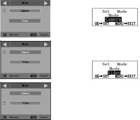
setting. The checkmark will appear next to your new setting to confirm this (Fig. 4c).
•On models with standard (non-color) display, only one setting is displayed at a time, starting with the current setting for the parameter when it is first selected (Fig. 4d). To change the setting, use the UP/ DOWN keys to display the new setting you want (Fig. 4e), then press OK to “Execute” (make the actual change to this setting). If you want to confirm this setting is now the current one, just press the RIGHT key to scroll to the next parameter, then press LEFT to go back again to the previous one. You should see the parameter setting you just made.
Fig. 4: Selecting Parameter Settings
|
COLOR VIEWER |
STANDARD DISPLAY |
|
(119477 only) |
|
|
|
|
|
|
Press MENU |
|
|
|
(4a) |
|
(4d) |
|
|
|
Press DOWN
(4b)
(4e)
Press OK
(4c)
14
EXAMPLES-Changing the Settings of Some Common Parameters
Following this page, you will find tables listing all of the parameters found in the SETUP Menu, along with their possible settings (or range of settings), and a detailed description of what the parameter controls and what the settings do. If you read the previous section detailing how to select parameters and change their settings, you should be able to dive right in, find the parameter(s) you want, and setup the camera to suit your preferences. But maybe you’d rather walk through an example or two first:
To change any parameter’s setting, always start with the power switch in the SETUP position. After the LCD comes on, press the MENU key.
The first parameter you will see when you first enter the SETUP Menu is “Mode”. To change it from its default setting of “Camera” (still photos) to “Video” (shoot video clips), press the DOWN key to highlight “Video” (119477 only) or to select the “Video” setting (std. display models). Press the OK key to “Execute” (Set) the new setting you’ve selected for this parameter.
Now press the RIGHT key to move to another parameter in the Menu. Pressing it three times will take you to “Capture Number”. Try using the UP and DOWN keys to scroll through the range of settings, then press OK to lock in your setting for the number of photos the camera takes each time it's triggered.
Pressing the RIGHT key until you reach the last menu item, you'll see the “Default Set” parameter. Highlight or select “Execute” (using UP or DOWN) and press OK to restore all parameters (including the Mode and Video Length parameters you changed a minute ago) back to their original factory default settings. The default settings for each parameter are indicated in bold type in the SETUP Menu tables on the next several pages.
Be sure to set the current date and time, using the “Set Clock” parameter, if you choose to change the “Time Stamp” parameter setting to “On” since that will tell the camera to imprint the date and time on each of the images it captures.
15
Field Scan 2x with Live Trigger Feature
Field Scan is a revolutionary new feature for the Bushnell Trophy Cam, which allows you to monitor your food plots or field edges with time lapse images or video. When set to “On”, the Trophy Cam will take a photo (or record a video clip) automatically at your choice of intervals (for example, once every five minutes) during one or two blocks of time you set up for each day, without requiring a trigger from an active animal. This has the advantage of giving you the ability to monitor the edge of a field that might be 50 or 150 yards away from the camera out of the PIR sensor’s range. The result is an effective range much greater than it would normally be, with the camera dependant on triggers generated by nearby animals. This is a great tool for hunters to scout an entire field with only one camera.
If an animal does enter the area covered by the PIR sensor and generate a trigger event during a time in between the Field Scan intervals you set, the camera will capture an image or video just as it normally would, based on your other menu settings. Here’s how to setup and use Field Scan (be sure you’ve set the current time in “Set Clock” first, so your Field Scan recording will stop and start at the correct times of day):
1.Move the main switch to SETUP, then press MENU.
2.Keep pressing the RIGHT key, stepping through the Setup Menu until you reach Field Scan.
3.Press the UP key to select On, and press OK (Step 1, pg.18). You will see "A", representing the first block of time you can define (a second block of time later in the day, "B" can also be setup if you wish). Press OK (Step 2). This takes you to the screen to set Start and Stop times, which determines the clock times when the first block of Field Scan recording will begin and end for each day. You can set these times to the exact hour and minute you want, for a recording “window” that lasts anywhere from just a minute to a full 24 hours.
4.Set the [Start] and [Stop] times, beginning with the Start hour, using the UP/DOWN keys to change the setting (Step 3). The hour setting is based on a 24-hour clock, with “00” hours = midnight, “12” hours = noon, “23” hrs = 11PM, etc. To move to the next setting, press the RIGHT key, change the minute for the Start time with UP/DOWN, then on to the hour and minute settings for the Stop time.
16
5.After you finish setting the Stop minutes, press OK to confirm your settings for the first block of Field Scan recording. If desired, you can create a second block of time by pressing the DOWN key to select "B" (Step 4), then press OK and follow the same process to set Start and Stop times for Field Scan block "B" (Step 5). As an example of how you might use these two available time blocks, you could setup Field Scan time block "A" for the dawn hours from 6 AM to 8 AM, and block "B" to capture images between 5:30 and 7 PM. No Field Scan recording would occur from 8AM to 5:30PM, or from 7PM to 6AM.
6.After setting Start/Stop times to define Field Scan block "A" and/or "B", press OK, then press the UP or DOWN key to select "Interval" and press OK (Step 6). The Field Scan "Interval" setting lets you control how often a photo or video clip is recorded during the block(s) of time you defined with the Start and Stop settings. Your options are 60 minutes, 30 minutes, 15 minutes, 5 minutes (this is the default), or 1 minute (still photo mode only). Use the UP/DOWN keys to select your preference, then press OK to save it (Step 7). Note that for videos, "Interval" is independent of the Length of each video recording-it’s how often videos are recorded, not how long each one lasts.
7.Here’s an example of how the camera would operate, based on the following Field Scan settings:
Field Scan: On
Field Scan A: [Start]: 6:00 [Stop]: 8:00
Field Scan B: [Start]: 17:30 [Stop]: 19:00 Interval: 15M
Note: avoid any "overlap" of Field Scan A & B recording blocks when setting their start and stop times, to assure correct operation.
These settings would cause the camera to capture a photo (or video, if the camera is set to that mode) once every 15 minutes, beginning at 6 AM, until the Field Scan "A" recording block stops at 8:00 AM. Later that day, the camera would again take a photo or video every 15 minutes between 5:30 PM and 7:00 PM (during Field Scan time block "B"). The next day, the camera would again record an image or video once every 15 minutes between 6:00 and 8:00 AM, and between 5:30 and
17

7:00 PM. No Field Scan recording would occur from 8AM to 5:30PM, or from 7PM to 6AM. Remember, Field Scan recording is independent of normal triggers due to animal activity–even if no animals enter the IR sensor coverage zone, an image or video will still be captured every 15 minutes during the block(s) of time. If an animal triggers the camera “in between” the 15 minute intervals, it will be recorded, same as it would if you had setup the camera with Field Scan turned Off. Note: Field Scan settings of frequent intervals and/or long periods between start and stop time can reduce battery life.
(Step 1)-set Field |
|
(Step 2)-select Field |
(Step 3)-set Field |
|
Scan Mode to “On” |
Scan "A" (press OK) |
Scan "A" Stop & Start |
||
Steps 4 & 5 are |
|
|
|
|
optional (only |
|
|
|
|
required if you want |
|
|
|
|
to set up a second |
|
|
|
|
block of Field Scan |
|
|
|
|
recording with |
(Step 4) (opt)-select Field (Step 5) (opt)-set Field |
|||
different stop and |
||||
|
Scan "B" (press OK) |
Scan "B" Stop & Start |
||
start times) |
|
|||
|
|
|
||
Note: the Interval Setting sets the timing between each image for both Field Scan "A" and "B" recording blocks.
(Step 6)-select Field |
(Step 7)-set Field |
Scan "Interval" |
Scan Interval |
18
The SETUP Menu – Parameters and Settings List w/Descriptions
Parameter |
Settings |
Description |
|
(Bold=default) |
|
|
|
|
Mode |
Camera or |
Selects whether still photos or |
|
Video |
video clips are captured when the |
|
|
camera is triggered. |
|
|
|
Image Size |
3M Pixel, |
Selects resolution for still photos |
(only affects |
5M Pixel, |
from 3 to 8 megapixels. Higher |
still photos) |
8M Pixel, |
resolution produces better quality |
|
|
photos, but creates larger files |
|
|
that take up more of the SD card |
|
|
capacity (fills up faster). 5M is a |
|
|
good compromise between quality |
|
|
and file size. |
|
|
|
Image Format |
Full Screen, |
Selects 4:3 (Fullscreen, like old |
(only affects |
Wide Screen |
TV sets) or 16:9 (Widescreen, like |
still photos-for- |
|
new flat TVs) “aspect ratio” for |
mat for video |
|
still photos. If you like to view your |
is tied to Video |
|
photos on a TV set or computer |
Size) |
|
monitor, you can set the format to |
|
|
match it. |
|
|
|
Capture |
1 Photo, |
Selects how many photos are |
Number |
2 Photo, |
taken in sequence per trigger |
(only affects |
3 Photo |
in Camera mode. This setting |
still photos) |
|
affects photos taken in Field Scan |
|
|
mode as well (to snap two photos |
|
|
every 10 minutes, for example). |
|
|
Please also refer to the Interval |
|
|
parameter. |
|
|
|
19
Parameter |
Settings |
Description |
|
(Bold=default) |
|
|
|
|
LED Control |
Low, Medium, |
Controls how many LED lamps |
(Multi-Flash |
High |
fire when images are taken in low |
feature) |
|
light. “High”=all 32 LEDs fire, |
|
|
which is the default setting. Set to |
|
|
Medium or Low if you are getting |
|
|
overexposed flash photos or will |
|
|
place the camera at very close |
|
|
range to the subject you want to |
|
|
photograph. Note: in video mode, |
|
|
24 LEDs fire in both High & |
|
|
Medium (default) settings. Set to |
|
|
Low if videos are overexposed. |
|
|
|
Camera |
(Input) |
Allows the user to set a custom |
Name |
|
name for the camera. Useful for ID |
|
See "Using the |
purposes when multiple cameras |
|
Setup Menu |
are setup, since each camera will |
|
Input Screens" |
imprint its name on all photos/ |
|
|
videos it captures. |
|
|
|
Video Size |
1280x720, |
Selects video resolution (in pixels |
(only affects |
640x480, |
per frame). Higher resolution |
video clips) |
320x240 |
produces better quality videos, but |
|
|
creates larger files that take up |
|
|
more of the SD card capacity (fills |
|
|
up faster). The default 640x480 |
|
|
is VGA video in standard 4:3 |
|
|
format. The 1280x720 setting |
|
|
provides “widescreen” format HD |
|
|
video. Using high speed SD cards |
|
|
(SanDisk® Ultra® or Extreme® |
|
|
series or similar) is recommended |
|
|
if you will use the 1280x720 video |
|
|
setting. |
|
|
|
20
Parameter |
Settings |
Description |
|
|
(Bold=default) |
|
|
|
|
|
|
Video |
10S (second) |
Sets length per captured video |
|
Length (only |
default, with |
clip. Settings begin with 10 |
|
affects video |
60S to5S |
second default when parameter is |
|
clips) |
possible range |
first selected. After stepping down |
|
to 5S, video length settings start |
|||
|
|
||
|
|
over at 60S. |
|
|
|
|
|
Interval |
10S (second) |
Selects the length of time that the |
|
|
default, |
camera will “wait” until it responds |
|
|
with a 60M |
to any additional triggers from the |
|
|
(minute) to1S |
PIR after an animal is first detected |
|
|
and remains within the sensor’s |
||
|
(second) range |
||
|
range. During this user set “ignore |
||
|
of settings |
||
|
triggers” interval, the camera will |
||
|
available. |
||
|
not capture photos/videos. This |
||
|
(60M-1M |
prevents the card from filling up |
|
|
with too many redundant images. |
||
|
are set in |
Settings begin with 10 second |
|
|
one minute |
default when parameter is first |
|
|
increments, |
selected. Note: after setting down |
|
|
past “1S”, settings start over at “60M”. |
||
|
59S-1S are set |
||
|
|
||
|
in one second |
|
|
|
increments) |
|
|
|
|
|
21
Parameter |
Settings |
Description |
|
(Bold=default) |
|
|
|
|
Sensor Level |
Low, Normal, |
Selects the sensitivity of the PIR |
|
High, Auto |
sensor. The “High” setting will |
|
|
make the camera more sensitive |
|
|
to infrared (heat) and more easily |
|
|
triggered by motion, and the “Low” |
|
|
setting makes it less sensitive to |
|
|
heat and motion. The High setting |
|
|
can be useful when the ambient |
|
|
temperature is warm (making it |
|
|
more difficult for the sensor to |
|
|
detect animals), and the Low |
|
|
setting may help in cold weather |
|
|
if the camera is being triggered |
|
|
too often by anything warmer than |
|
|
the surroundings. “Normal” is for |
|
|
average or moderate conditions. |
|
|
The default “Auto” setting will |
|
|
allow the camera to determine the |
|
|
best setting based on its current |
|
|
operating temperature. This is |
|
|
an ideal setting if the weather is |
|
|
expected to change significantly |
|
|
during the period the camera will |
|
|
be used. |
|
|
|
22
Parameter |
Settings |
Description |
|
(Bold=default) |
|
|
|
|
Format |
Execute |
Deletes (erases) all files stored |
|
(followed by an |
on a card to prepare it for reuse. |
|
additional No/Yes |
Always format a card that has |
|
step) |
been previously used in other |
|
|
devices. Caution! Make sure |
|
|
you have downloaded and |
|
|
backed up any files you want |
|
|
to preserve first! Press OK to |
|
|
execute (then select Yes and press |
|
|
OK again on color viewer models), |
|
|
press MENU (or select NO then |
|
|
press OK) to exit without formatting. |
|
|
|
TV Out |
NTSC, PAL |
Selects video standard /format |
|
|
for the “A/V Out” output jack. The |
|
|
video standard is NTSC for the |
|
|
United States, Canada, Mexico, |
|
|
Asia and South America. PAL is |
|
|
used primarily in Europe. |
|
|
|
Time Stamp |
Off, On |
Select “On” if you want the |
|
|
date & time (that the photo was |
|
|
captured) imprinted on every |
|
|
photo/video, select “Off” for |
|
|
no imprint. Note: the current |
|
|
temperature, moon phase, and |
|
|
(user set) camera name will also |
|
|
be imprinted on your still photos. |
|
|
Models 119476/119477 imprint |
|
|
the barometric pressure as well (in |
|
|
"Camera" mode only). |
|
|
|
23
Parameter |
Settings |
Description |
|
(Bold=default) |
|
|
|
|
Set Clock |
(Set) |
Press OK and use the UP/DOWN |
|
|
keys (to change the setting) and |
|
|
LEFT/RIGHT keys ( to move |
|
|
to the next field) to set the hour |
|
|
(24-hr format only, “00”=midnight, |
|
|
“12”=noon) and minute, and then |
|
|
(on the lower row), the year, month |
|
|
and date. |
|
|
|
Field Scan |
On, Off |
Turns Field Scan (Time Lapse) |
|
(After On is se- |
recording mode on/off. When |
|
lected): “A” Start/ |
activated, Field Scan forces the |
|
Stop, “B” Start/ |
camera to take photos or videos |
|
Stop, Interval |
even when it is not triggered by |
|
|
a nearby live animal, useful for |
|
|
constant monitoring of an area |
|
|
that might be far away from the |
|
|
camera. The user can set the |
|
|
start and stop times for up to two |
|
|
independent “blocks” of Field |
|
|
Scan recording, as well as the |
|
|
interval time between each photo/ |
|
|
video. To ensure correct operation, |
|
|
avoid setting overlapping start/ |
|
|
stop times for Field Scan A and B. |
|
|
Please read the “Field Scan 2x…” |
|
|
section of this manual for details |
|
|
on using this feature. |
|
|
|
24
Parameter |
Settings |
Description |
|
(Bold=default) |
|
|
|
|
Coordinate |
Off, On |
Allows the user to input latitude |
Input |
|
and longitude coordinates for the |
|
See "Using the |
camera’s location. This data will |
|
Setup Menu |
be embedded in the files saved on |
|
Input Screens" |
the camera’s SD card (if “On” is |
|
|
selected). This makes it possible |
|
|
to see each camera’s location as a |
|
|
“pushpin” on Google Earth maps |
|
|
when reviewing a folder full of pho- |
|
|
tos from multiple cameras, or use |
|
|
other “geotag” capable software |
|
|
(Picassa, etc). |
|
|
|
Video Sound |
On, Off |
Select “On” to record audio along |
(only affects |
|
with the video when the camera is |
video clips) |
|
set to video mode (saved file sizes |
|
|
will be slightly larger). |
|
|
|
Default Set |
Cancel, |
Select “Execute” and press OK |
|
Execute |
to restore all parameters to the |
|
|
original factory default settings. |
|
|
If the camera is behaving oddly |
|
|
and you think you may have |
|
|
changed the setting for something |
|
|
accidently (but aren’t sure which |
|
|
one), this will reset all parameters |
|
|
to their most commonly used or |
|
|
“generic” settings. |
|
|
|
25

USING THE SETUP MENU INPUT SCREENS
Camera Name Input
After selecting the Camera Name parameter (the only setting is "Input"), press OK. If necessary, delete the previous or default name by pressing the RIGHT key until the backspace symbol ( ) (located between letters "A" & "B", also between "j" & "k") is highlighted, then keep pressing OK. Select (highlight) each alphanumeric character you want, using the LEFT/RIGHT keys, and pressing OK after each one to set it. When finished naming the camera, press MENU to save the name to memory.
Coordinate Input
After selecting the Coordinate Input parameter, press UP or DOWN to select the On setting and press OK. The latitude and longitude for any location where you plan to place the camera can be obtained at many websites, for example: http://itouchmap.com/latlong.html. You can enter a nearby street address, just zip code, or use the various types of maps to locate the approximate position. The format you will need to use to enter the coordinates in the Trophy Cam menu screen is shown below:
|
|
|
|
|
Degrees |
|
|
||
N=North, |
Latitude |
Minutes |
Seconds |
||||||
S=South |
(3 digits) |
||||||||
|
|
||||||||
Latitude |
|
|
|
|
|
||||
|
|
(La) N000,00'00" |
|
||||||
|
|
|
|||||||
Longitude |
|
(Lo) W000,00'00" |
|
||||||
|
|
||||||||
|
|
|
|
|
|
|
|
|
|
W=West, |
Degrees |
Minutes |
Seconds |
||||||
Longitude |
|||||||||
E=East |
(3 digits) |
|
|
||||||
Note: You may see "negative" latitude or longitude coordinates online. These designate South latitudes and West longitudes. US/Canada locations will have North (+) latitude coordinates and West (-) longitude coordinates.
26
 Loading...