


TRS-25
Red Dot Sight
Illuminated Red Dot Scope • owner's manual Lunette à point rouge lumineux • Manuel d’utilisation Visor de Punto Rojo iluminado • Manual del propietario Zielfernrohr mit rotem Leuchtpunkt • Bedienungsanleitung
MODEl #: 731303 / 731309 / AR731306 / AR731306C
Lit. #: 93-0512/03-13

TABLE OF CONTENTS |
PAGE |
ENGLISH |
3-8 |
Français |
9-14 |
Español |
15-20 |
Deutsch |
21-26 |
A C
B
Model#
731303 / 731309
D 
AR731306 / AR731306C only
2
ENGLISH
The Bushnell® TRS-25 is a small, light and rugged red dot sight, designed for use on shotguns, rifles and handguns. It is constructed and assembled by highly skilled craftsmen to Bushnell’s high quality standards. The precision and craftsmanship with which this scope was built ensures its performance under demanding conditions. This scope will provide the shooting accuracy and repeatability which have made Bushnell legendary.
This sight can be easily used with both eyes open (eye relief is unlimited), increasing the shooter's awareness of the surrounding environment and providing faster target acquisition. There is no need for centering, due to the parallax free design in which the dot follows the movement of the user’s eye while remaining fixed on the target. The TRS-25 delivers full size performance in a sight with reduced size and low power consumption.
The model# AR731306/AR731306C versions of the TRS-25 include a tall riser block (D, pg. 2) to position the sight at an optimum height on AR-15 flat tops or tactical shotguns.
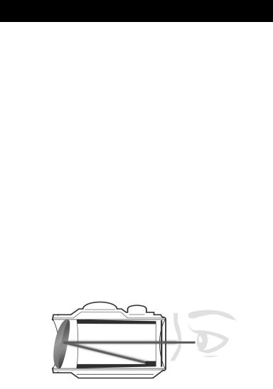
About Red Dot Lens Positioning
All red dot sights have an objective lens at the front of the unit that is spherical in shape. However, unlike a conventional riflescope with all lenses mounted perpendicular (at a 90 degree angle) to the axis of the tube, the objective lens in a red dot sight is positioned off axis and appears to be tilted when looking at the sight (see below). This angle of the front lens allows the light generated by the battery powered LED light source inside the unit to be reflected back into the sight. The reflected light becomes the “dot” or aiming reference that the shooter sees when a red dot sight is switched on. This engineered “bending” of light is what makes today’s red-dot sights so popular and easy to use.
3
SETUP AND OPERATION
WARNING: Insure the weapon is unloaded and the safety selector is in the ”safe” position before attempting to install, remove or perform maintenance on the sight.
Installing the Battery
1.Remove Battery Cap (A) by turning it counter clockwise.
2.Insert a battery (type CR2032) with positive (+) end toward Cap.
3.Install Battery Cap by turning clockwise until snug. Hand tighten only, using a coin or similar item. Using tools could damage the equipment.
Note: (not necessary when the sight is new) Before installing the Battery Cap, inspect that the O-ring is present and not damaged. Failure to do so could result in water leakage into the battery compartment.
4.Verify that red dot is present by turning the Rotary Switch (B) clockwise.
Installing the Sight on the Firearm (w/o Hi-Rise Block)
The TRS-25 is designed for installation on most types of weapons, which have a MIL-Std 1913 Picatinny Rail or Weaver Rail. If your weapon does not have or support an appropriate base(s), please consult your dealer, gunsmith or other qualified source.
Installing the Sight on a Picatinny/Weaver Rail (w/o Hi-Rise Block)
1.Loosen the Shaft by means of the Allen Wrench, so that the Locking Bar can clamp around the Picatinny/ Weaver Rail.
2.Install the Sight to the weapon Rail by tightening the Shaft. First, ensure that the Sight is correctly positioned and that the Shaft fits into a groove on the Picatinny/Weaver Rail. To make sure that the Shaft is firmly tightened, screw the Shaft clockwise until a light resistance can be encountered. After that, screw another 1/4 to 1/2 turn. WARNING!
Do not overtighten.
3.When using Lens Covers, ensure that they are correctly positioned and can easily be opened.
4.Finally, make sure that the Shaft with Locking Bar is firmly tightened around the weapon Rail.
5.Complete zeroing according to the "Zeroing" section on page 6.
4
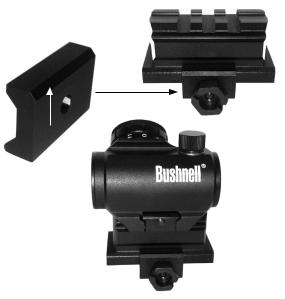
Installing the Sight on the Firearm with Hi-Rise Block (AR models only)
The AR731306/AR731306C versions of the TRS-25 are supplied with a "HiRise" mounting block that can be used to position the sight at the correct height for optimum performance on an AR-15 style rifle with a flat top receiver.
In order to use the riser block, first install the sight onto the block by following steps 1-4 in the previous section ("Installing the sight on a Picatinny/Weaver Rail"). Once the sight is installed on the Hi-Rise block, the entire assembly can be mounted on the weapon by following these steps:
1.Loosen the mounting screw so that the clamp will fit over the tapered side of the firearm’s Picatinny or Weaver rail.
2.Insure that the tapered clamp on the riser is oriented with the chamfered (beveled) end of the clamp at the top (Fig. 1).
3.Ensure that the riser’s cross screw with nut is tightened to clamp it firmly to the weapon’s rail (Fig. 2). Turn the large nut on the riser block ¼ to ½ turn with a coin, screwdriver or ½” wrench. WARNING! Do not over tighten.
4.Complete zeroing according to the "Zeroing" section on page 6.
Fig. 1
Fig. 2
5
Lens Covers
In order to preclude the loss of the lens covers when removed from the optical path of the Sight, the lens covers should be removed downwards. The rubber string will then grab around the Sight and Base.
Zeroing
The TRS-25 is delivered with the red dot in a centered position. Normally this means that only small adjustments are necessary, providing that the weapon rail (Picatinny/Weaver Rail) is properly aligned.
CAUTION: Do not continue to adjust windage and elevation mechanisms if you encounter resistance.
The Elevation Adjustment Screw is located on top of the sight, while the Windage Adjustment Screw is located on the right side.
1.Open (remove) Lens Covers .
2.Turn the Switch Knob (B) clockwise until the red dot has a sufficient intensity to contrast against the target.
3.Remove the Adjustment Cap (C) for windage and elevation adjustment, one at a time.
4.Confirm zeroing by firing at least three shots at a zeroing target. Check points of impact on zeroing target to confirm accuracy and repeat above procedure if required.
5.After initial firing, ensure that the sight is secure.
6.Turn Rotary Switch to OFF position (counter clockwise).
7.Close front and rear Lens Covers.
OPERATION UNDER EXTREME CONDITIONS
•Extreme heat (moist or dry): No special procedures required.
•Extreme cold: Extreme cold might shorten battery life. It could also make the Rotary Switch a little harder to turn than at normal temperatures.
•Salt air: No special procedures required.
•Sea spray, water, mud and snow: Ensure that Battery Cap and the two Adjustment Caps are tightened before exposing the Sight to sea spray, mud, snow or before immersing the sight in water. Hand tighten only. Keep Lens Covers closed when sight is not being used. Clean lenses with lens paper/cloth and wipe the sight dry as soon as possible after exposure to water, sea spray, mud or snow.
6
•Dust storms and sand storms: Keep Lens Covers closed when sight is not being used.
CAUTION: The lenses shall never be cleaned with fingers but with lens paper/ cloth. If no lens paper/cloth is available:
•To clear away debris (sand, grass etc): blow away the dirt.
•To clean lenses (after any debris is removed): breathe on the lenses and clean them with a soft cloth.
TROUBLE SHOOTING
Problem: Red Dot Does Not Appear
Possible Causes/Solutions:
•Discharged battery: Replace battery.
•Battery installed incorrectly: Remove and reinstall battery with (+) toward Cap.
•Battery is not making good contact: Clean contact surfaces and reinstall battery.
•Defective Rotary Switch: Notify dealer/armourer.
Problem: Impossible To Zero
Possible Causes/Solutions:
•Adjustment screw is at its limit: Check alignment of mount to barrel.
•Impact point is moving: Check mount and weapon rail (or carry handle) stability.
7
ONE-YEAR LIMITED WARRANTY
Your Bushnell® product is warranted to be free of defects in materials and workmanship for one year after the date of purchase. In the event of a defect under this warranty, we will, at our option, repair or replace the product, provided that you return the product postage prepaid. This warranty does not cover damages caused by misuse, improper handling, installation, or maintenance provided by someone other than a Bushnell Authorized Service Department.
Any return made under this warranty must be accompanied by the items listed below:
1.A check/money order in the amount of $10.00 to cover the cost of postage and handling
2.Name and address for product return
3.An explanation of the defect
4.Proof of Date Purchased
5.Product should be well packed in a sturdy outside shipping carton, to prevent damage in transit, with return postage prepaid to the address listed below:
IN U.S.A. Send To: |
IN CANADA Send To: |
Bushnell Outdoor Products |
Bushnell Outdoor Products |
Attn.: Repairs |
Attn.: Repairs |
9200 Cody |
25A East Pearce Street, Unit 1 |
Overland Park, Kansas 66214 |
Richmond Hill, Ontario L4B 2M9 |
For products purchased outside the United States or Canada please contact your local dealer for applicable warranty information.
In Europe you may also contact Bushnell at:
Bushnell Germany GmbH
European Service Centre
Mathias-Brüggen-Str. 80
D-50827 Köln
GERMANY
Tel: +49 221 995568-0
Fax: +49 221 995568-20
This warranty gives you specific legal rights.
You may have other rights which vary from country to country. ©2013 Bushnell Outdoor Products
8

FCC Note:
This equipment has been tested and found to comply with the limits for a Class B digital device, pursuant to Part 15 of the FCC Rules. These limits are designed to provide reasonable protection against harmful interference in a residential installation. This equipment generates, uses and can radiate radio frequency energy and, if not installed and used in accordance with the instructions, may cause harmful interference to radio communications. However, there is no guarantee that interference will not occur in a particular installation. If this equipment does cause harmful interference to radio or television reception, which can be determined by turning the equipment off and on, the user is encouraged to try to correct the interference by one or more of the following measures:
•Reorient or relocate the receiving antenna.
•Increase the separation between the equipment and receiver.
•Connect the equipment into an outlet on a circuit different from that to which the receiver is connected.
•Consult the dealer or an experienced radio/TV technician for help.
Shielded interface cable must be used with the equipment in order to comply with the limits for a digital device pursuant to Subpart B of Part 15 of FCC Rules.
Specifications and designs are subject to change without any notice or obligation on the part of the manufacturer.
9

Français
Félicitations pour votre choix de la TRS-25 lunette à point rouge lumineux de Bushnell. Ce lunette a été spécialement conçu pour être utilisé sur les fusils, les carabines et les pistolets. Il est construit et assemblé par des artisans hautement qualifiés selon les hauts standards de qualité de Bushnell. La précision et la connaissance du métier avec lesquelles ce lunette a été construit garantissent ses performances dans les conditions les plus rudes. Les viseurs Bushnell à point rouge sont conçus pour une utilisation les deux yeux ouverts, ce qui permet un meilleur champ de vision et une plus grande vitesse d’acquisition de la cible. Grâce à sa conception sans parallaxe, le point rouge suit les mouvements de l’oeil en restant fixe sur la cible, ce qui élimine le besoin de centrage. De plus, les viseurs Aimpoint autorisent une distance oculaire illimitée. Ce lunette vous permettra un tir précis même après des tirs répétés, caractéristique qui a contribué à la réputation légendaire de Bushnell.
Les modèles AR731306 et AR731306C du TRS-25 comprennent un épais pavé de surélévation (D, page 2) pour que le viseur soit à une hauteur optimale sur les AR-15 à sommet plat ou les fusils tactiques.
À propos du positionnement de la lentille à point rouge
Tous les viseurs à point rouge sont équipés d'une lentille d'objectif de forme sphérique à l'avant de l'appareil. Cependant, contrairement à une lunette de tir conventionnelle, où toutes les lentilles sont montées perpendiculairement (angle de 90 degrés) à l'axe du tube, la lentille d'objectif d'un viseur à point rouge est positionnée en dehors de l'axe et semble inclinée lorsqu'elle fait face au viseur (voir ci-dessous). Cet angle de la lentille avant permet à la lumière générée par la DEL de la batterie d'alimentation située à l'intérieur de l'appareil d'être réfléchie de nouveau dans le viseur. La lumière réfléchie devient le « point » ou la référence de pointage que le photographe aperçoit lorsqu'un point rouge est allumé. Le « fléchissement » de lumière produit est ce qui rend les viseurs à point rouge si populaires et faciles d'utilisation de nos jours.
10
 Loading...