

Burkert 8694 User Manual [en, de, fr]
Type 8694
Positioner TopControl Basic
Electropneumatic position controller
Elektropneumatischer Stellungsregler
Positionneur électropneumatique
Operating Instructions
Bedienungsanleitung
Manuel d‘utilisation
We reserve the right to make technical changes without notice.
Technische Änderungen vorbehalten.
Sous réserve de modifications techniques.
© 2008 - 2014 Bürkert Werke GmbH
Operating Instructions 1403/04_EU-ML_00805886 / Original DE
Type 8694
Positioner Type 8694
Table of ConTenTs
1. OPERATING INSTRUCTIONS ........................................................................................................................................................7
1.1. Symbols
AUTHORIZED USE .............................................................................................................................................................................8
2.
2.1. Restrictions
BASIC SAFETY INSTRUCTIONS .................................................................................................................................................9
3.
GENERAL INFORMATION .............................................................................................................................................................10
4.
Contact address ..................................................................................................................................................................10
4.1.
4.2. Warranty
4.3. Trademarks
Information on the internet ............................................................................................................................................10
4.4.
SYSTEM DESCRIPTION ................................................................................................................................................................11
5.
Intended application area ...............................................................................................................................................11
5.1.
Function of the positioner and combination with valve types ....................................................................11
5.2.
Features of the valve types ...........................................................................................................................................12
5.3.
......................................................................................................................................................................................7
...............................................................................................................................................................................8
...................................................................................................................................................................................10
............................................................................................................................................................................10
Structure of the positioner ............................................................................................................................................13
5.4.
5.4.1. Representation .........................................................................................................................................13
5.4.2. Features .....................................................................................................................................................14
5.4.3. Function diagram of the positioner with single-acting actuator ...................................................15
Type 8694 positioner (position controller) ............................................................................................................16
5.5.
5.5.1. Schematic representation of the position control Type 8694.......................................................16
5.5.2. Functions of the position controller software ....................................................................................17
Interfaces of the positioner ..........................................................................................................................................19
5.6.
TECHNICAL DATA .............................................................................................................................................................................20
6.
6.1. Conformity
6.2. Standards
Operating conditions ........................................................................................................................................................20
6.3.
Mechanical data ...................................................................................................................................................................20
6.4.
..............................................................................................................................................................................20
................................................................................................................................................................................20
3
English

Type 8694
6.5. Pneumatic data ....................................................................................................................................................................21
Type label ...............................................................................................................................................................................21
6.6.
Electrical data .......................................................................................................................................................................22
6.7.
6.7.1. Electrical data without bus control 24 V DC ....................................................................................22
6.7.2. Electrical data with AS-Interface bus control ...................................................................................22
Factory settings of the positioner ..............................................................................................................................23
6.8.
CONTROL AND DISPLAY ELEMENTS ...................................................................................................................................24
7.
Operating status ...................................................................................................................................................................... 24
7.1.
Control and display elements of the positioner .................................................................................................24
7.2.
Configuration of the keys ................................................................................................................................................... 26
7.3.
Function of the DIP switches ........................................................................................................................................... 28
7.4.
Display of the LEDs ............................................................................................................................................................... 30
7.5.
Error messages ....................................................................................................................................................................... 31
7.6.
7.6.1. Error messages in MANUAL and AUTOMATIC operating statuses ..............................................31
7.6.2. Error messages while the X.TUNE function is running ...................................................................31
8. INSTALLATION
Safety instructions .............................................................................................................................................................32
8.1.
Installation of the positioner Type 8694
8.2.
...................................................................................................................................................................................32
on process valves of series 2103, 2300 and 2301 ...........................................................................................32
Installing the positioner Type 8694 on
8.3.
process valves belonging to series 26xx and 27xx ................................................................................................ 35
Rotating the actuator module ......................................................................................................................................39
8.4.
Rotating the positioner for
8.5.
process valves belonging to series 26xx and 27xx ..........................................................................................41
FLUID INSTALLATION ....................................................................................................................................................................42
9.
Safety instructions .............................................................................................................................................................42
9.1.
Installing the process valve ...........................................................................................................................................42
9.2.
Pneumatic connection of the positioner ................................................................................................................43
9.3.
4
English
Type 8694
10. ELECTRICAL INSTALLATION 24 V DC ...................................................................................................................................44
Safety instructions .............................................................................................................................................................44
10.1.
Electrical installation with circular plug-in connector .....................................................................................44
10.2.
10.2.1. Designation of the contacts Type 8694 .............................................................................................44
10.2.2. Connection of the positioner Type 8694 ...........................................................................................45
Electrical installation with cable gland ....................................................................................................................46
10.3.
10.3.1. Designation of the screw-type terminals ...........................................................................................46
10.3.2. Connection of the positioner Type 8694 ...........................................................................................46
AS-INTERFACE INSTALLATION ................................................................................................................................................48
11.
AS-Interface connection .................................................................................................................................................48
11.1.
Technical data for AS-Interface PCBs .....................................................................................................................48
11.2.
Programming data ..............................................................................................................................................................48
11.3.
Communication sequence for the version S-7.A.5 profile ..........................................................................49
11.4.
LED status display ..............................................................................................................................................................50
11.5.
Electrical installation AS-interface ............................................................................................................................51
11.6.
11.6.1. Safety instructions ...................................................................................................................................51
11.6.2. Connection with circular plug-in connector M12 x 1, 4-pole, male ............................................51
11.6.3. Connection with multi-pole cable and ribbon cable terminal........................................................52
12. START-UP
12.1.
12.2.
.............................................................................................................................................................................................53
Safety instructions .............................................................................................................................................................53
Specifying the standard settings ................................................................................................................................53
12.2.1. Running the automatic adjustment X.TUNE .............................................................................53
OPERATION AND FUNCTION ....................................................................................................................................................55
13.
Basic functions ........................................................................................................................................................................ 55
13.1.
13.1.1. DIR.CMD - Effective direction of the positioner set-point value ................................................. 56
13.1.2. CUTOFF - Sealing function for the positioner .................................................................................57
13.1.3. CHARACT - Select the transfer characteristic between input signal
(position set-point value) and stroke ..........................................................................58
Auxiliary functions .................................................................................................................................................................. 59
13.2.
SAFETY POSITIONS .......................................................................................................................................................................60
14.
Safety positions after failure of the electrical or pneumatic auxiliary power .....................................60
14.1.
English
5

Type 8694
15. MAINTENANCE ..................................................................................................................................................................................61
Safety instructions .............................................................................................................................................................61
15.1.
Service at the air intake filter .......................................................................................................................................62
15.2.
16. ACCESSORIES
Communications software (PC SOFTWARE based on FDT/DTM technology) .................................63
16.1.
..................................................................................................................................................................................63
16.1.1. PACTware 3.6 ..........................................................................................................................................63
16.1.2. USB interface ...........................................................................................................................................63
16.1.3. Download ..................................................................................................................................................63
17. DISASSEMBLY
Safety instructions .............................................................................................................................................................64
17.1.
Disassembly the positioner ...........................................................................................................................................64
17.2.
PACKAGING AND TRANSPORT ...............................................................................................................................................66
18.
19. STORAGE
20. DISPOSAL
...................................................................................................................................................................................64
..............................................................................................................................................................................................66
............................................................................................................................................................................................66
6
English
Type 8694
Operating instructions
1. OPERATING INSTRUCTIONS
The operating instructions describe the entire life cycle of the device. Keep these instructions in a location which is
easily accessible to every user, and make these instructions available to every new owner of the device.
WARNING!
The operating instructions contain important safety information!
Failure to observe these instructions may result in hazardous situations.
• The operating instructions must be read and understood.
1.1. Symbols
DANGER!
Warns of an immediate danger!
• Failure to observe the warning will result in a fatal or serious injury.
WARNING!
Warns of a potentially dangerous situation!
• Failure to observe the warning may result in serious injuries or death.
CAUTION!
Warns of a possible danger!
• Failure to observe this warning may result in a moderate or minor injury.
NOTE!
Warns of damage to property!
• Failure to observe the warning may result in damage to the device or the equipment.
Indicates important additional information, tips and recommendations.
refers to information in these operating instructions or in other documentation.
→ Designates a procedure which you must carry out.
7
English
Type 8694
Authorized use
2. AUTHORIZED USE
Non-authorized use of the positioner Type 8694 may be a hazard to people, nearby equipment and the
environment.
• The device is designed to be mounted on pneumatic actuators of process valves for the control of media.
• Do not expose the device to direct sunlight.
• Use according to the authorized data, operating conditions and conditions of use specified in the contract
documents and operating instructions. These are described in the chapter entitled “6. Technical data”.
• The device may be used only in conjunction with third-party devices and components recommended and
authorized by Bürkert.
• In view of the large number of options for use, before installation, it is essential to study and if necessary to
test whether the positioner is suitable for the actual use planned.
• Correct transportation, correct storage and installation and careful use and maintenance are essential for reliable and faultless operation.
• Use the positioner Type 8694 only as intended.
2.1. Restrictions
If exporting the system/device, observe any existing restrictions.
8
English
Type 8694
Basic safety instructions
3. BASIC SAFETY INSTRUCTIONS
These safety instructions do not make allowance for any
• contingencies and events which may arise during the installation, operation and maintenance of the devices.
• local safety regulations – the operator is responsible for observing these regulations, also with reference to the
installation personnel.
DANGER!
Danger – high pressure!
• Before dismounting pneumatic lines and valves, turn off the pressure and vent the lines.
Risk of electric shock!
• Before reaching into the device or the equipment, switch off the power supply and secure to prevent reactivation!
• Observe applicable accident prevention and safety regulations for electrical equipment!
General hazardous situations.
To prevent injury, ensure:
• that the system cannot be activated unintentionally.
• Installation and repair work may be carried out by authorized technicians only and with the appropriate tools.
• After an interruption in the power supply or pneumatic supply, ensure that the process is restarted in a defined
or controlled manner.
• The device may be operated only when in perfect condition and in consideration of the operating instructions.
• The general rules of technology apply to application planning and operation of the device.
To prevent damage to property on the device, ensure:
• Do not feed any aggressive or flammable media into the pilot air port.
• Do not feed any liquids into the pilot air port.
• Do not put any loads on the body (e.g. by placing objects on it or standing on it).
• Do not make any external modifications to the device bodies. Do not paint the body parts or screws.
NOTE!
Electrostatic sensitive components / modules!
• The device contains electronic components, which react sensitively to electrostatic discharge (ESD). Contact
with electrostatically charged persons or objects is hazardous to these components. In the worst case scenario,
they will be destroyed immediately or will fail after start-up.
• Observe the requirements in accordance with EN 100 015 - 1 and 5 - 2 to minimize or avoid the possibility of
damage caused by sudden electrostatic discharge!
• Also ensure that you do not touch electronic components when the power supply is on!
English
9
Type 8694
Basic safety instructions
The positioner Type 8694 was developed with due consideration given to the accepted safety rules and is
state-of-the-art. Nevertheless, dangerous situations may occur.
Failure to observe this operating manual and its operating instructions as well as unauthorized tampering with
the device release us from any liability and also invalidate the warranty covering the devices and accessories!
4. GENERAL INFORMATION
4.1. Contact address
Germany
Bürkert Fluid Control System
Sales Center
Chr.-Bürkert-Str. 13-17
D-74653 Ingelfingen
Tel. + 49 (0) 7940 - 10 91 111
Fax + 49 (0) 7940 - 10 91 448
E-mail: info@de.buerkert.com
International
Contact addresses can be found on the final pages of the printed operating instructions.
And also on the Internet at:
www.burkert.com
4.2. Warranty
The warranty is only valid if the positioner Type 8694 is used as intended in accordance with the specified application conditions.
4.3. Trademarks
Brands and trademarks listed below are trademarks of the corresponding companies / associations / organizations
Loctite Henkel Loctite Deutschland GmbH
4.4. Information on the internet
The operating instructions and data sheets for Type 8694 can be found on the Internet at:
www.burkert.com
10
English
Type 8694
System description
5. SYSTEM DESCRIPTION
5.1. Intended application area
The positioner Type 8694 is designed to be mounted on pneumatic actuators of process valves for the control of
media.
5.2. Function of the positioner and combination with
valve types
Positioner Type 8694 is an electropneumatic position controller for pneumatically actuated control valves with
single-acting actuators.
Together with the pneumatic actuator, the positioner forms a functional unit.
The control valve systems can be used for a wide range of control tasks in fluid technology and, depending on the
application conditions, different process valves belonging to series 2103, 2300, 2301, 26xx or 27xx from the Bürkert
range can be combined with the positioner. Angle-seat valves, diaphragm valves or ball valves fitted with a control
cone are suitable.
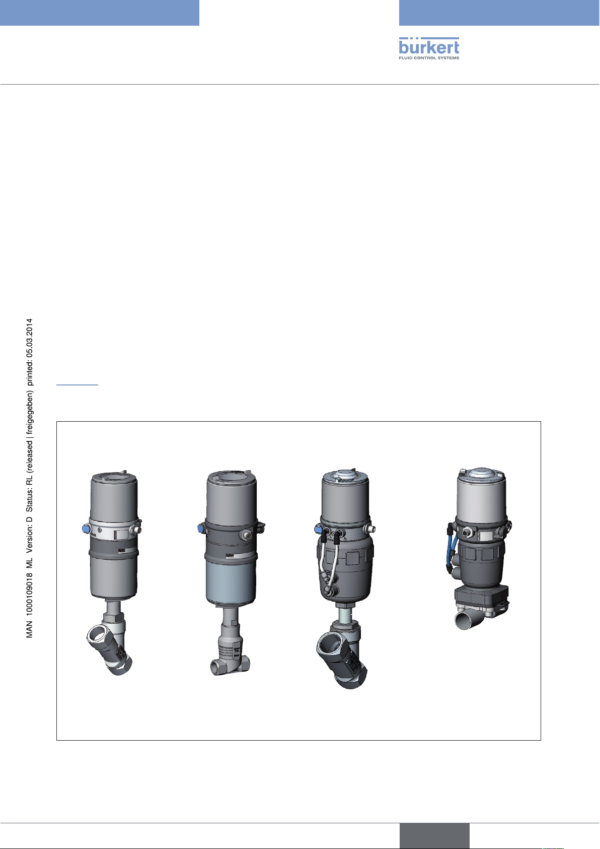
“Figure 1” shows an overview of the possible combinations of positioner and different pneumatically actuated valves.
Different actuator sizes and valve nominal widths, not illustrated here, are available for each type. More precise
specifications can be found on the respective data sheets. The product range is being continuously expanded.
Positioner Type 8694
with diaphragm
valve
with angle seat valve
Type 2300
Figure 1: Overview of possible combinations
with straight seat valve
Type 2301
Type 2730
with angle seat valve
Type 2702
11
English
Type 8694
System description
The position of the actuator is regulated according to the position set-point value. The position set-point value is
specified by an external standard signal.
Pneumatically actuated piston actuators and rotary actuators can be used as an actuator. Single-acting actuators
are offered in combination with the positioner.
For single-acting actuators, only one chamber is aerated and deaerated in the actuator. The generated pressure works
against a spring. The piston moves until there is an equilibrium of forces between compressive force and spring force.
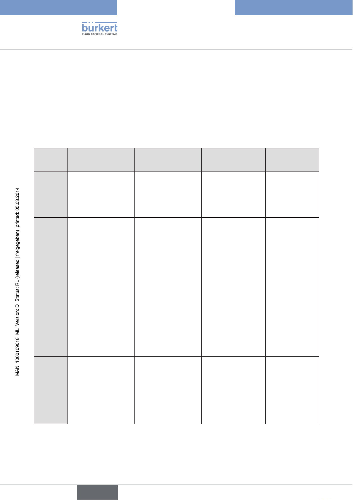
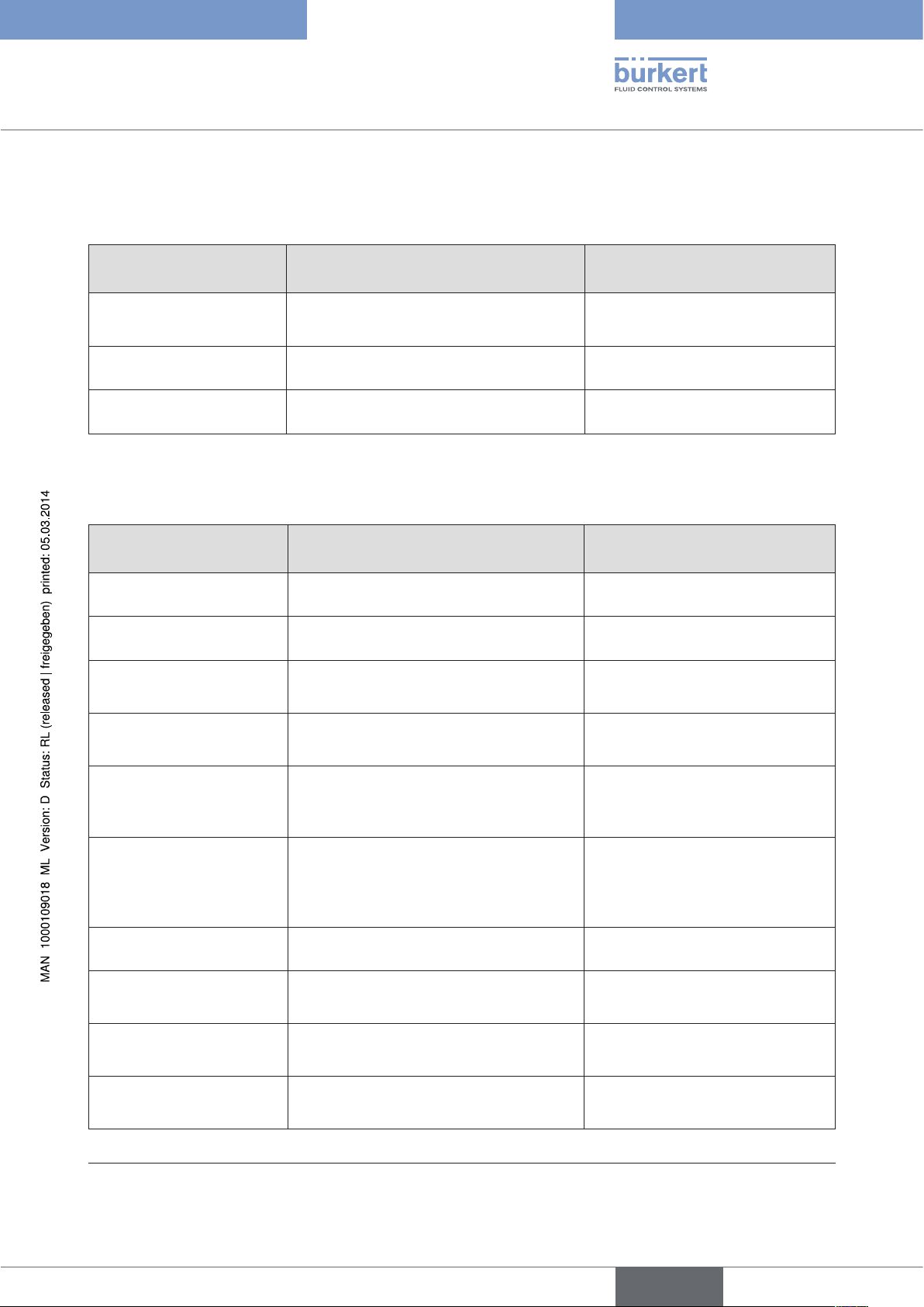
5.3. Features of the valve types
Types
Features
Angle seat control
valves / straight seat
control valves
• 2300
• 2301
• 2702
• 2712
• incoming flow under
seat
• no closing impact
• straight flow path of
the medium
• self-adjusting
stuffing box for high
leak-tightness
Diaphragm valves Ball valves Flap valves
• 2103
• 2730
• 2731
• medium is hermetically separated from
the actuator and
environment
• cavity-free and selfdraining body design
• any flow direction with
low-turbulence flow
• steam-sterilizable
• CIP-compliant
• no closing impact
• 2652
• 2655
• 2658
• scrapable
• minimum dead space
• unaffected by
contamination
• little pressure loss
compared to other
valve types
• seat and seal can
be exchanged in the
three-piece ball valve
when installed
• 2672
• 2675
• unaffected by
contamination
• little pressure
loss compared to
other valve types
• inexpensive
• low construction
volume
12
Typical
media
Table 1: Features of the valve types
• water, steam and
gases
• alcohols, oils, propellants, hydraulic fluids
• salt solutions, lyes
(organic)
• solvents
English
• actuator and diaphragm can be
removed when the
body is installed
• neutral gases and
liquids
• contaminated,
abrasive and
aggressive media
• media of higher
viscosity
Note
can be used as
process controller only
• neutral gases and
liquids
• clean water
• slightly aggressive
media
• neutral gases
and liquids
• slightly
aggressive media
Type 8694
System description
5.4. Structure of the positioner
The positioner Type 8694 consists of the micro-processor controlled electronics, the position measuring system
and the control system. The device is designed using three-wire technology. The positioner is operated via 2 keys
and a 4-pole DIP switch. The pneumatic control system for single-acting actuators consists of 2 solenoid valves.
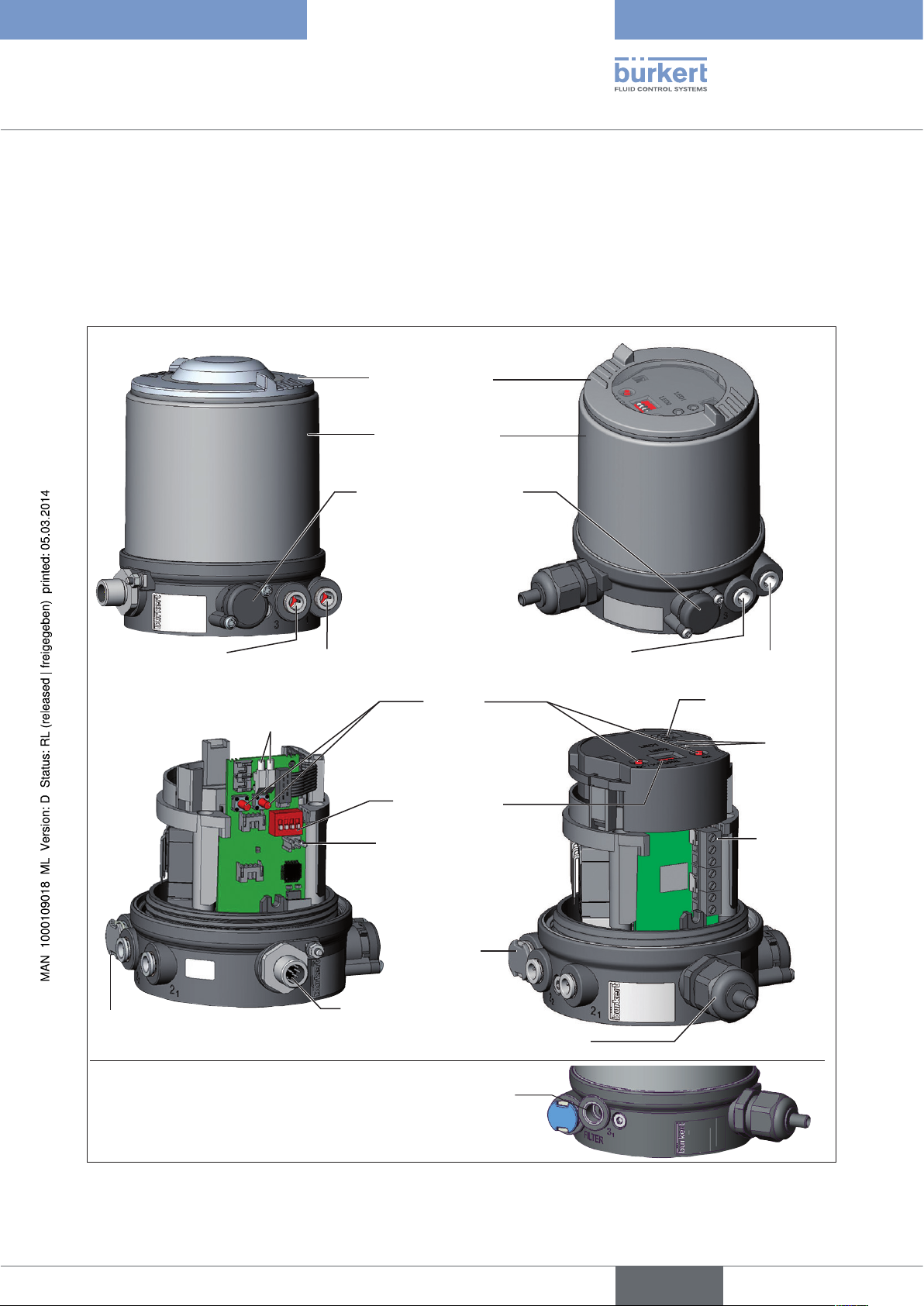
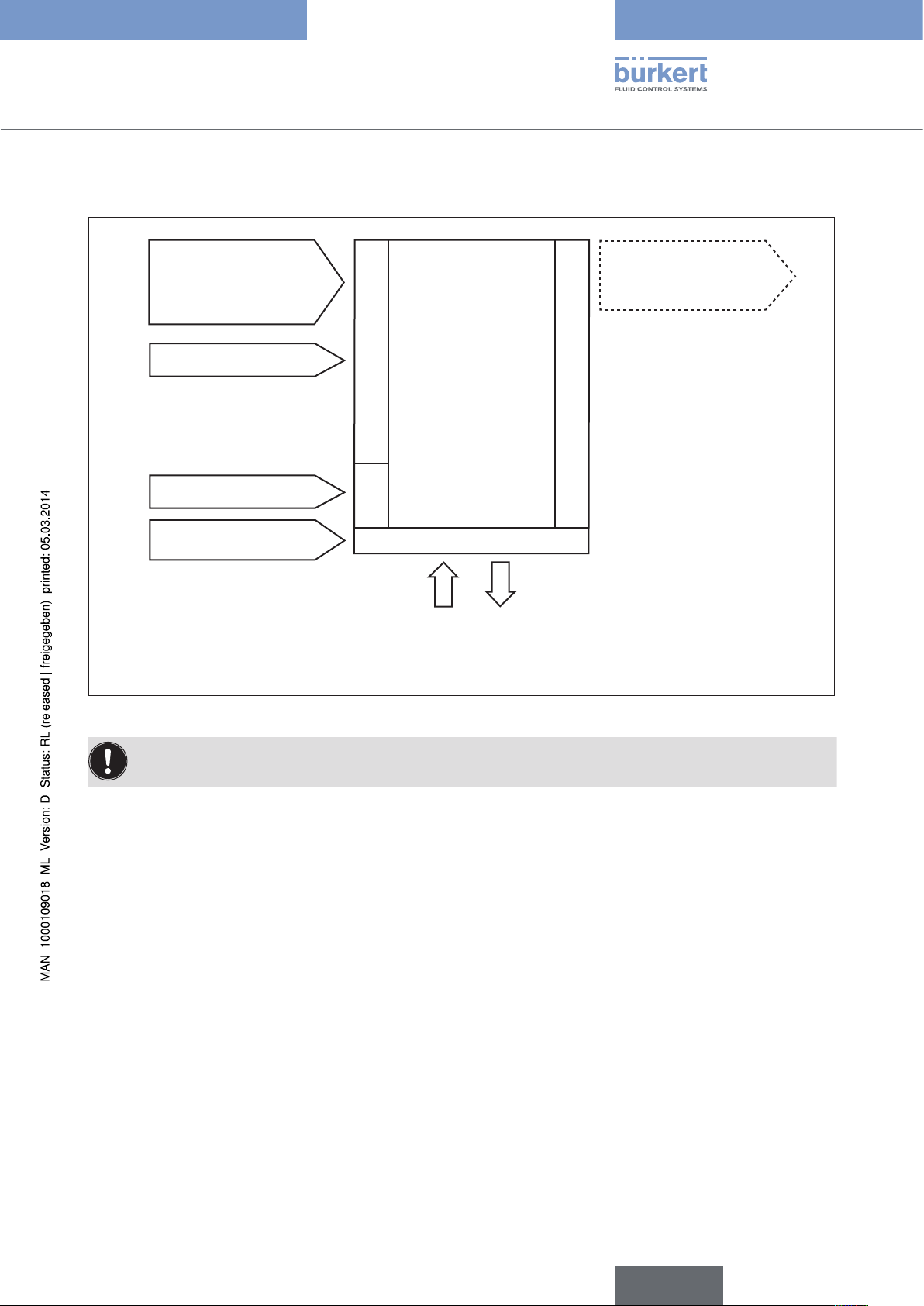
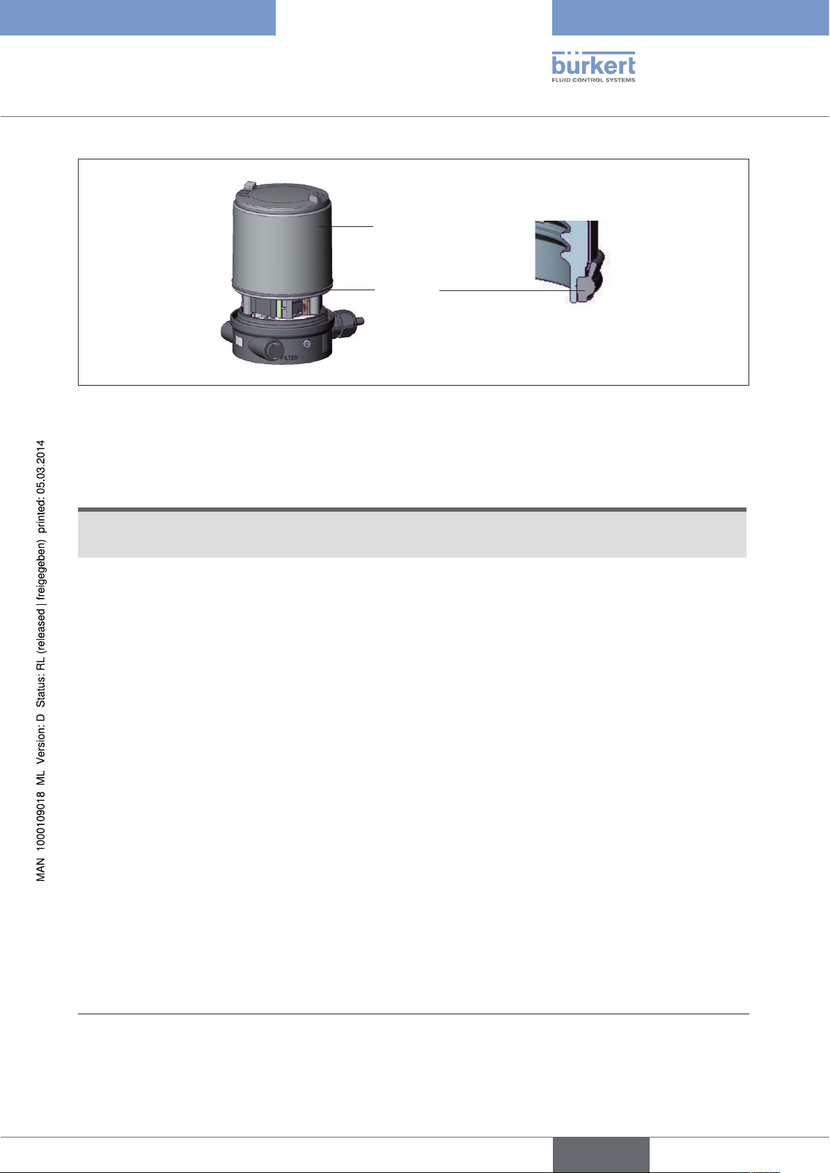
5.4.1. Representation
Version 1
Exhaust air connection (label: 3)
Body casing removed:
Transparent cap
Body casing
Pressure limiting valve
(for protection against too
high internal pressure in
case of error)
Pressure supply connection
(label: 1)
LED
Buttons
Version 2
Exhaust air connection (label: 3)
Pressure supply
connection (label: 1)
Communications
interface
LED
Air intake filter
(exchangeable)
with pilot-operated control system for high air output
Figure 2: Structure
DIP Switches
Communications
interface
Air intake
filter
(exchangeable)
Electrical connection
(cable gland M16 x 1.5
or circular plug-in connector M12 x 1)
Additional exhaust air port (label: 3.1)
only for Type 23xx and 2103
(actuator size ø 130)
Screwtype
terminals
13
English
Type 8694
System description
5.4.2. Features
• Models
for single-acting valve actuators.
• Position measuring system
Contactless and therefore wear-free position measuring system.
• Microprocessor-controlled electronics
for signal processing, control and valve control.
• Control module
The device is controlled via 2 buttons and a 4-pole DIP switch. 2x 2-colored LEDs indicate different statuses of
the device.
• Control system
The control system consists of 2 solenoid valves. One valve is used to aerate and another to deaerate the
pneumatic actuator. The solenoid valves operate according to the rocker principle and are controlled with a
PWM voltage via the controller. Doing so achieves a higher flexibility with regard to actuator volume and final
control speed. The direct-action model has an orifice of DN 0.6. In larger pneumatic actuators the solenoid
valves feature diaphragm amplifiers to increase the maximum flow and therefore to improve the dynamics (DN
2.5).
• Position feedback (optional)
The position of the valve can be transmitted to the PLC via an analog 0/4-20 mA output.
• Binary input
If a voltage > 10 V is applied, SAFE POSITION is activated, i.e. the valve is moved to the safety position
(factory setting, can be changed with communications software).
• Pneumatic interfaces
1/4“ connections with different thread forms
(G, NPT)
hose plug-in connection
• Electrical interfaces
Circular plug-in connector or cable gland
Pneumatic interface
14
Electrical interface
• Body
The body of the positioner is protected from excessively high internal pressure, e.g. due to leaks, by a pressure
limiting valve.
• Communications interface
For configuration and parameterization.
English

English
Type 8694
System description
5.4.3. Function diagram of the positioner with single-acting
actuator
The illustrated function diagram describes the function of the positioner (Type 8694).
external
position
set-point value
Position
controller
Control system
1
2
Control system
1: Aeration valve
2: Bleed valve
Pressure
supply
Positioner
Actual
position
Position
measuring
system
Pneumatic actuator
(single-acting)
Valve
(actuator)
Exhaust air
Figure 3: Function diagram
15
Type 8694
System description
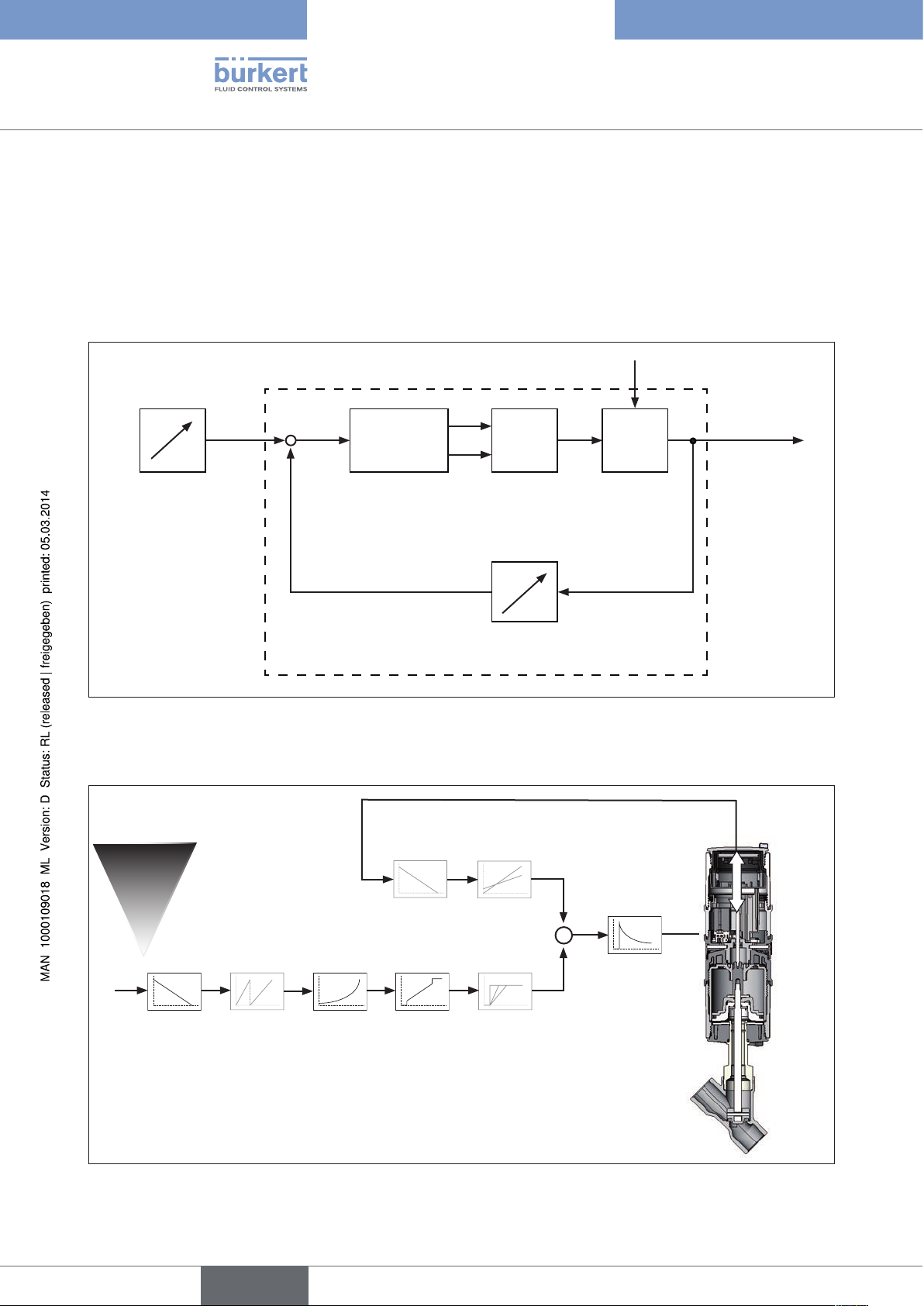
5.5. Type 8694 positioner (position controller)
The position measuring system records the current position (POS) of the pneumatic actuator. The position controller
compares this actual position value with the set-point value (CMD) which is definable as standard signal. In case
of a control deviation (Xd1), a pulse-width modulated voltage signal is sent to the control system as a manipulated variable. If there is a positive control difference in single-acting actuators, the air inlet valve is controlled via
output B1. If the control difference is negative, the bleed valve is controlled via output E1. In this way the position
of the actuator is changed until control difference is 0. Z1 represents a disturbance variable.
Z1
B1
Position
set-point
CMD Xd1
+
-
Position
controller
E1
Solenoid valves
P
K
Valve opening
Control valveControl system
value
POS
Position control
circuit
Position measuring system
Figure 4: Signal flow plan of position controller
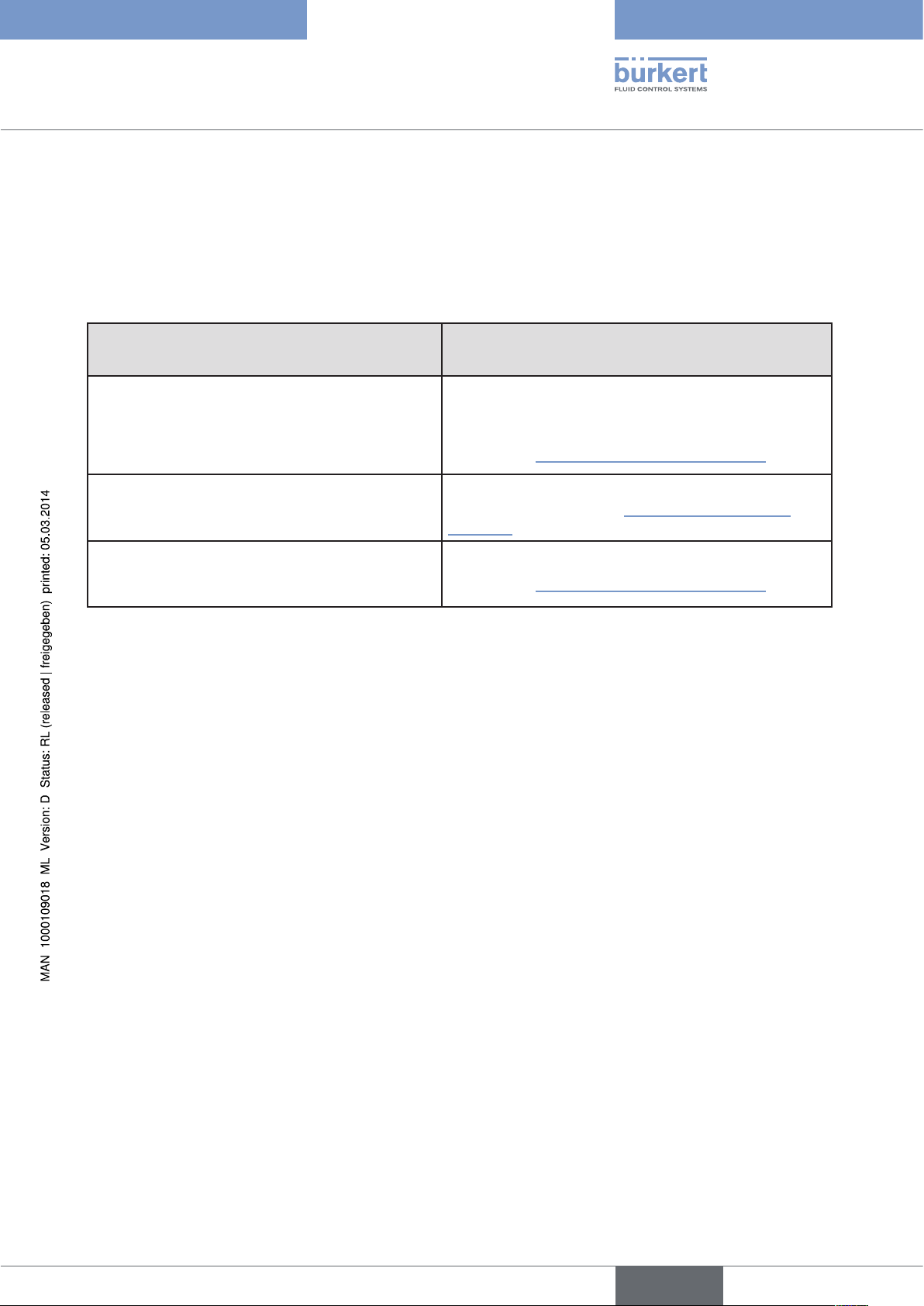
5.5.1. Schematic representation of the position control Type 8694
16
4 ... 20 mA1)
0 ... 20 mA
DIR.ACT
INP
DIR.CMD
1) Default setting
2) Can only be activated with communications software
Figure 5: Schematic representation of position control
SPLTRNG
2)
CHARACT
CUTOFF
English
2)
X.LIMIT
X.TIME
POS
2)
CMD
2)
POS
CMD
X.CONTROL
DBND
Type 8694
System description
5.5.2. Functions of the position controller software
Functions I
• Activation via DIP switches
• Parameter setting via communications software
Additional function Effect
Sealing function
CUTOFF
Correction line to adjust the operating characteristic
CHARACT
Effective direction of the controller set-point value
DIR.CMD
Table 2: Functions I
Valve closes tight outside the control range. Specification
of the value (as %), from which the actuator is completely
deaerated (when 0 %) or aerated (when 100 %)
(see chapter “7.4. Function of the DIP switches”).
Linearization of the operating characteristic can be
implemented (see chapter “7.4. Function of the DIP
switches”).
Reversal of the effective direction of the set-point value
(see chapter “7.4. Function of the DIP switches”).
English
17
Functions II
• Activation and parameter setting via communications software
Additional function Effect
Type 8694
System description
Standard signal for set-point value
INPUT
Effective direction of the actuator
DIR.ACTUATOR
Signal split range
SPLITRANGE
Mechanical stroke range limit
X.LIMIT
Opening and closing time
X.TIME
Position controller
X.CONTROL
Safety position
SAFE POSITION
Select set-point value standard signal
Assignment of the aeration status of the actuator
chamber to the actual position.
Standard signal as % for which the valve runs through
the entire mechanical stroke range.
Limit the mechanical stroke range
Limit the control speed
Parameterize the position controller
Definition of the safety position
18
Signal level fault detection
Configuration of signal level fault detection
SIGNAL ERROR
Binary input
Configuration of the binary input
BINARY INPUT
Analog output
Configuration of the analog output (optional)
OUTPUT
Reset
Reset to factory settings
RESET
Table 3: Functions II
English
Type 8694
System description
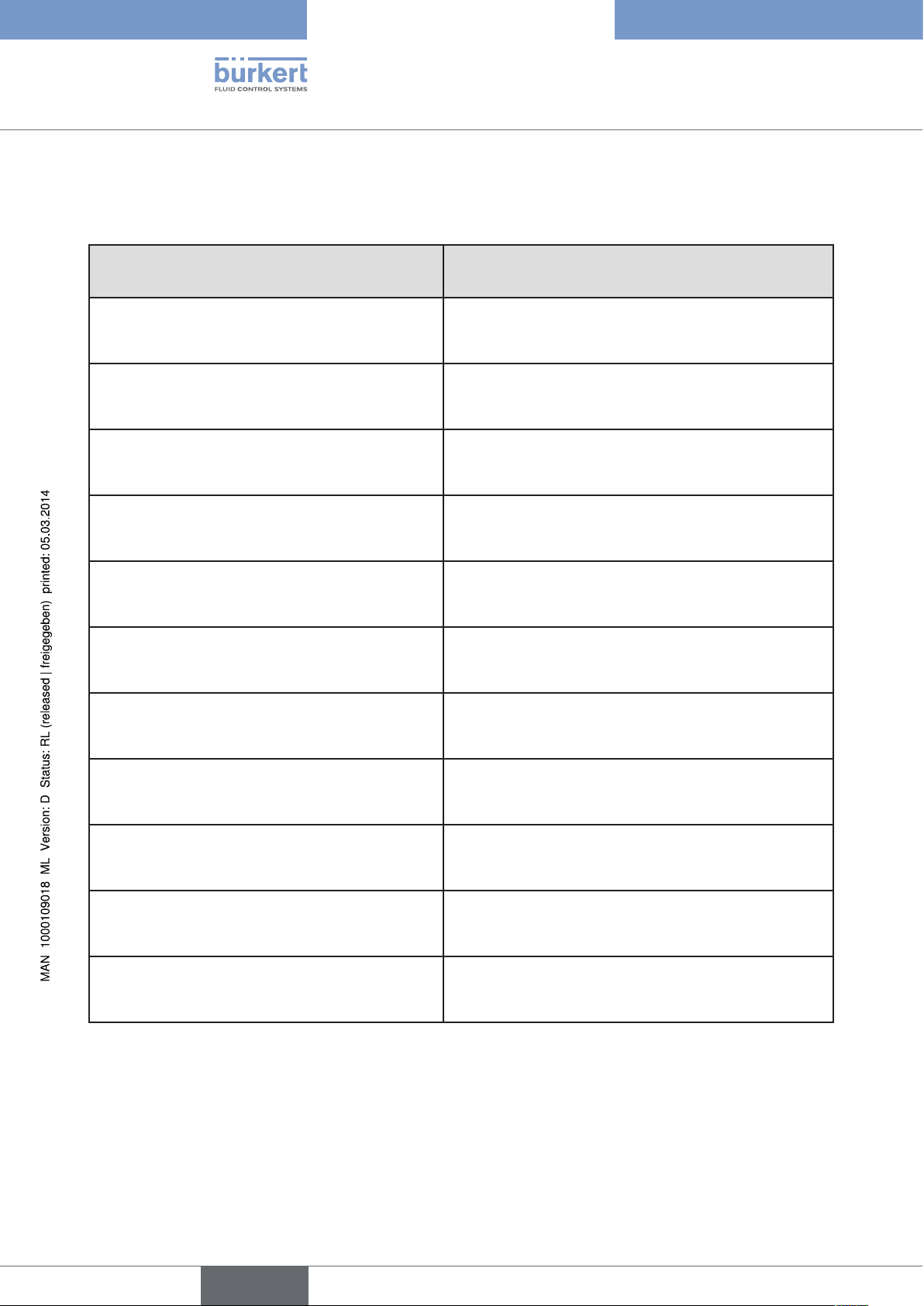
5.6. Interfaces of the positioner
Input for position
set-point value3)
4 – 20 mA4)
0 – 20 mA
Binary input
Inputs
24 V DC
Communications
Power
interface
3) Or optional bus connection AS interface
4) Default setting
Positioner
Operation
Analog
position feedback
(optional)
Outputs
Figure 6: Interfaces
The positioner Type 8694 is a 3-wire device, i.e. the power (24 V DC) is supplied separately from the setpoint value signal.
• Input for position set-point value (4 – 20 mA corresponds to 0 – 100 %
(depending on position of DIP switch 1)).
• Binary input
If a voltage > 10 V is applied, SAFE POSITION is activated, i.e. the valve is moved to the safety position
(factory setting, can be changed with communications software).
• Analog position feedback (optional)
The position of the valve can be transmitted via an analog 4 – 20 mA output to the PLC
(4 – 20 mA corresponds to 0 – 100 %).
English
19
Type 8694
Technical data
6. TECHNICAL DATA
6.1. Conformity
In accordance with the EC Declaration of conformity, the positioner Type 8694 is compliant with the EC Directives.
6.2. Standards
Conformity with the EC Directives is verified by the following standards.
EN 61000-6-3, EN 61000-6-2, EN 61010-1
6.3. Operating conditions
WARNING!
Solar radiation and temperature fluctuations may cause malfunctions or leaks.
• If the device is used outdoors, do not expose it unprotected to the weather conditions.
• Ensure that the permitted ambient temperature does not exceed the maximum value or drop below the minimum value.
Ambient temperature 0 ... +60 °C
Protection class: IP65 / IP67 according to EN 60529
(only if cables, plugs and sockets have been connected correctly
and in compliance with the exhaust air concept in chapter “Pneumatic
connection of the positioner”)
6.4. Mechanical data
Dimensions See data sheet
Body material exterior: PPS, PC, VA,
interior: PA 6; ABS
Sealing material EPDM / (NBR)
20
Stroke range of valve spindle: 3 ... 45 mm
English
Type 8694
Technical data
6.5. Pneumatic data
Control medium neutral gases, air
Quality classes in accordance with DIN ISO 8573-1
Dust content Class 5 max. particle size 40 µm, max. particle density 10 mg/m³
Water content Class 3 max. pressure dew point
- 20 °C or min. 10 °C below the lowest operating temperature
Oil content Class 5 max. 25 mg/m³
Temperature range
of the compressed air 0 ... +60 °C
Pressure range 3 ... 7 bar
Air output of control valve 7 lN / min (for aeration and deaeration)
(QNn - value according to definition for pressure drop from 7 to 6 bar absolute)
optional:
130 lN / min (for aeration and deaeration)
(only single-acting)
Connections Plug-in hose connector Ø6 mm / 1/4"
Socket connection G1/8
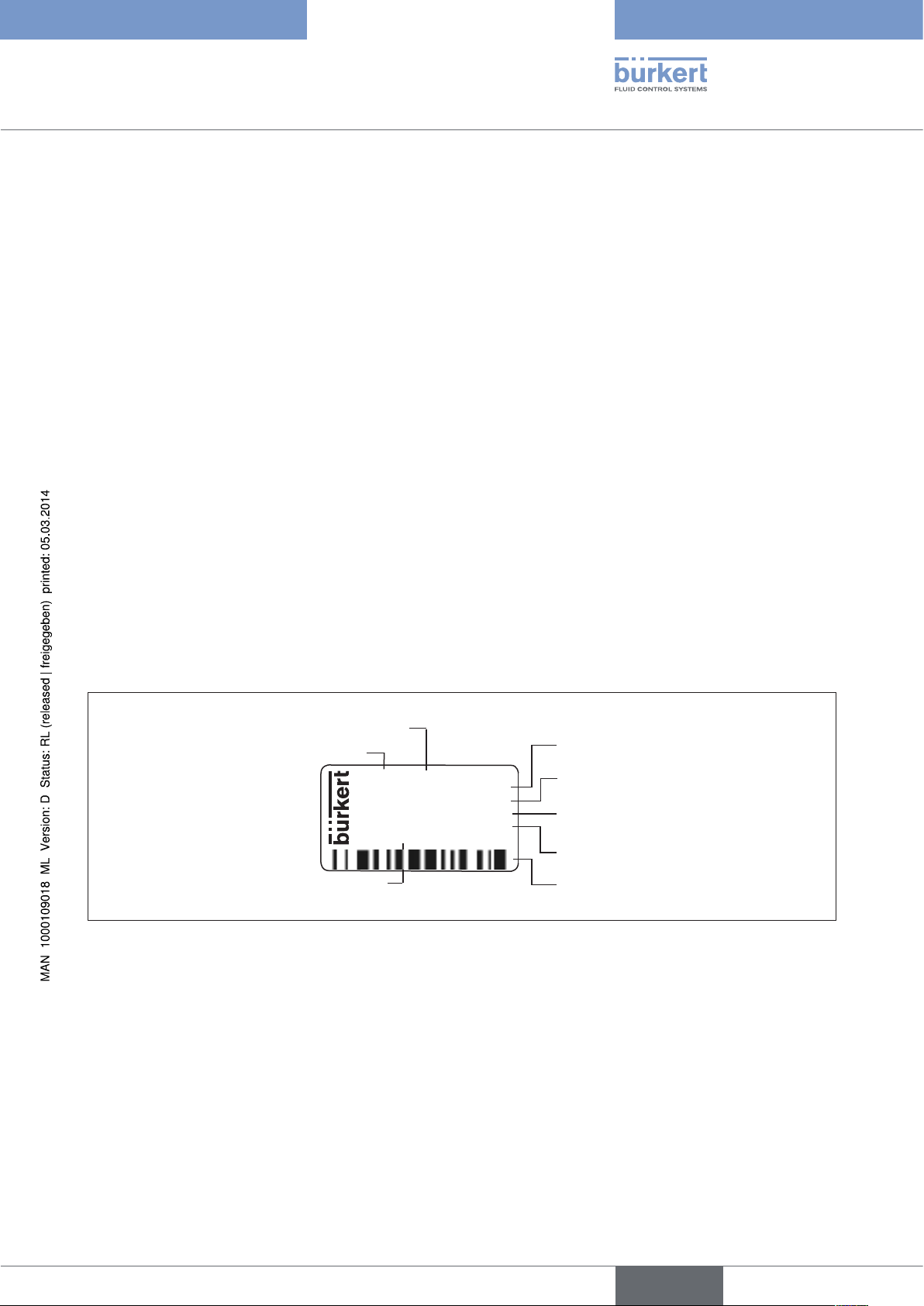
6.6. Type label
Supply voltage / Control
Control function - Pilot valve
Nominal pressure
Max. ambient temperature
Serial number - CE mark
Bar-code
Figure 7: Example of type label
Identification number
Type
8694 24 V DC
single act Pilot 0,6
Pmax 7bar
Tamb 0°C - +60°C
S/N 001000
00185134
D-74653 Ingelfingen
W14UN
CE
English
21
Type 8694
Technical data
6.7. Electrical data
6.7.1. Electrical data without bus control 24 V DC
Connections Cable gland M16 x 1.5, wrench size 22 (clamping area 5 – 10 mm)
with screw-type terminals for cable cross-sections 0.14 – 1.5 mm²
Circular plug-in connector (M12 x 1, 8-pole)
Control valve
Power supply 24 V DC ± 10% - max. residual ripple 10 %
Power input ≤ 3.5 W
Input resistance
for set-point value signal 75 Ω at 0/4 - 20 mA / 12 bit resolution
Protection class 3 in accordance with VDE 0580
Analogue position feedback
max. load
for current output 0/4 – 20 mA 560 Ω
Binary input 0 – 5 V = log “0”, 12 - 30 V = log “1”
inverted input in reverse order
Communications interface Direct connection to PC via USB adapter with integrated interface driver,
communication with communications software based on FDT/DTM
technology, see “Table 34: Accessories”.
6.7.2. Electrical data with AS-Interface bus control
Connections Circular plug-in connector (M12 x 1, 4-pole)
Electrical supply voltage 29.5 V – 31.6 V DC (according to specification)
Devices without external supply voltage:
Max. power consumption 150 mA
Devices with external supply voltage:
External supply voltage 24 V ± 10 %
The power supply unit must
include a secure disconnection in
accordance with IEC 364-4-41
(PELV or SELV)
22
Max. power consumption 100 mA
Max. power consumption
from AS-Interface 50 mA
English
Type 8694
Technical data
6.8. Factory settings of the positioner
Functions can be activated via DIP switches:
Function Parameter Value
CUTOFF
CHARACT
DIR.CMD
Table 4: Factory settings - Functions I
Sealing function below
Sealing function above
2 %
98 %
Select characteristic FREE
Effective direction set-point value rise
Functions can be activated via communications software:
Function Parameter Value
INPUT
DIR.ACTUATOR
SPLITRANGE
Function deactivated
X.LIMIT
Function deactivated
Set-point value input 4 ... 20 mA
Effective direction actual value rise
Signal split range below
Signal split range above
Stroke limit below
Stroke limit above
0 %
100 %
0 %
100 %
5)
X.TIME
Function deactivated
Actuating time Open
Actuating time Closed
(1 s) values determined by X.TUNE
(1 s) values determined by X.TUNE
After implementation of RESET: 1 s
X.CONTROL
Deadband
Open amplification factor
Close amplification factor
1,0 %
(1) values determined by X.TUNE
(1) values determined by X.TUNE
After implementation of RESET: 1
SAFE POSITION
SIGNAL ERROR
Safety position 0 %
Sensor break detection set-point value OFF
Function deactivated
BINARY INPUT
OUTPUT
(optional)
Table 5: Factory settings Functions II
5) Without change to the settings via the communications software a linear characteristic is stored in FREE.
Binary input function
Operating principle of binary input
Norm signal output: Parameter
Norm signal output: Type
Safety position
Normally open
Position
4 – 20 mA
23
English
Type 8694
Control and display elements
7. CONTROL AND DISPLAY ELEMENTS
The following chapter describes the operating statuses as well as the control and display elements of the positioner.
Further information on the operation of the positioner can be found in the chapter entitled “12. Start-up”.
7.1. Operating status
AUTOMATIC (AUTO)
Normal controller mode is implemented and monitored in AUTOMATIC operating status.
→ LED 1 flashes green.
MANUAL
In MANUAL operating status the valve can be opened and closed manually via the keys.
→ LED 1 flashes red / green alternately.
DIP switch 4 can be used to switch between the two operating statuses AUTOMATIC and MANUAL.
ON DIP
2 3 4
1
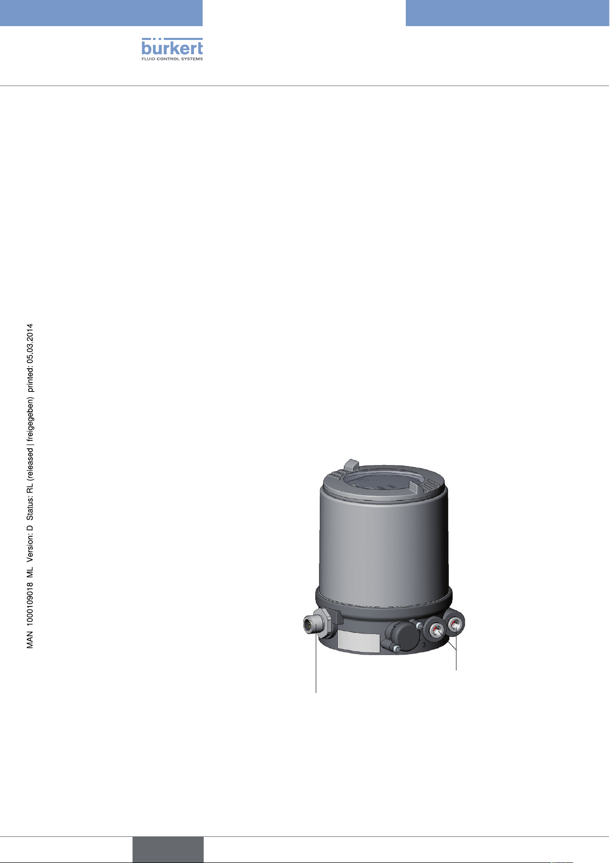
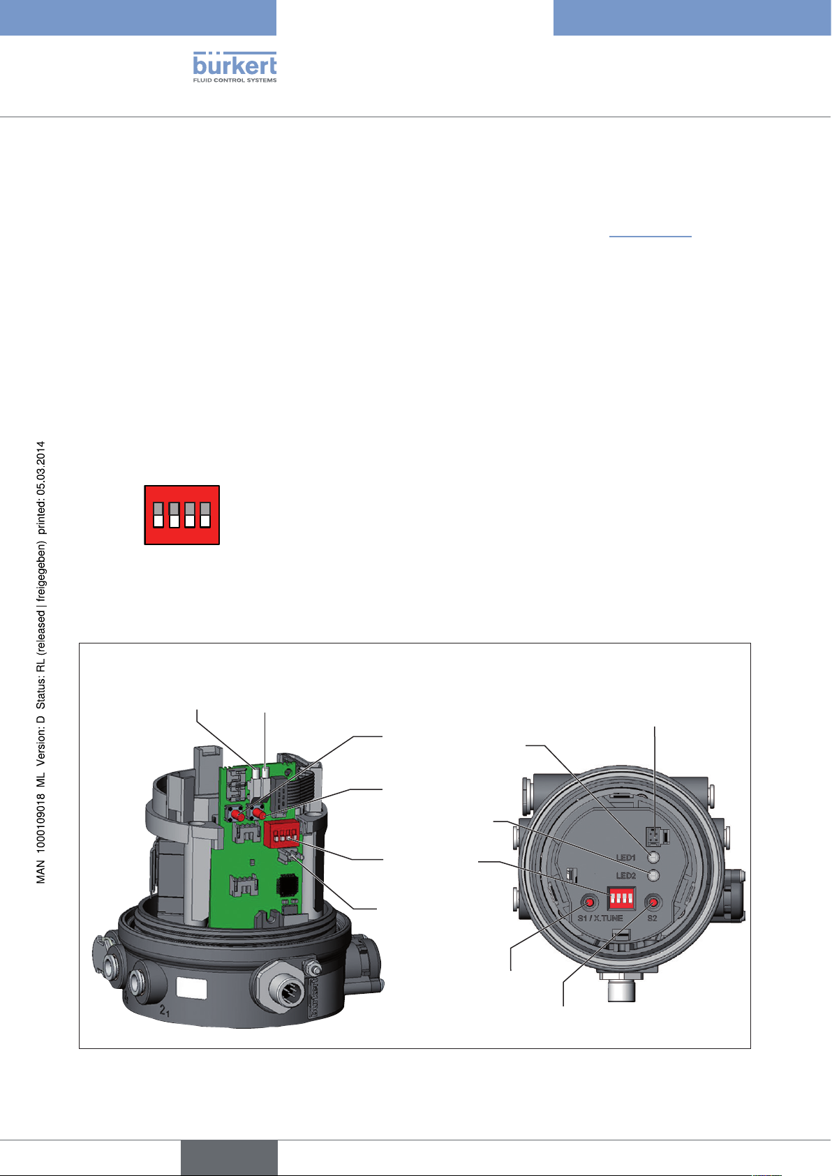
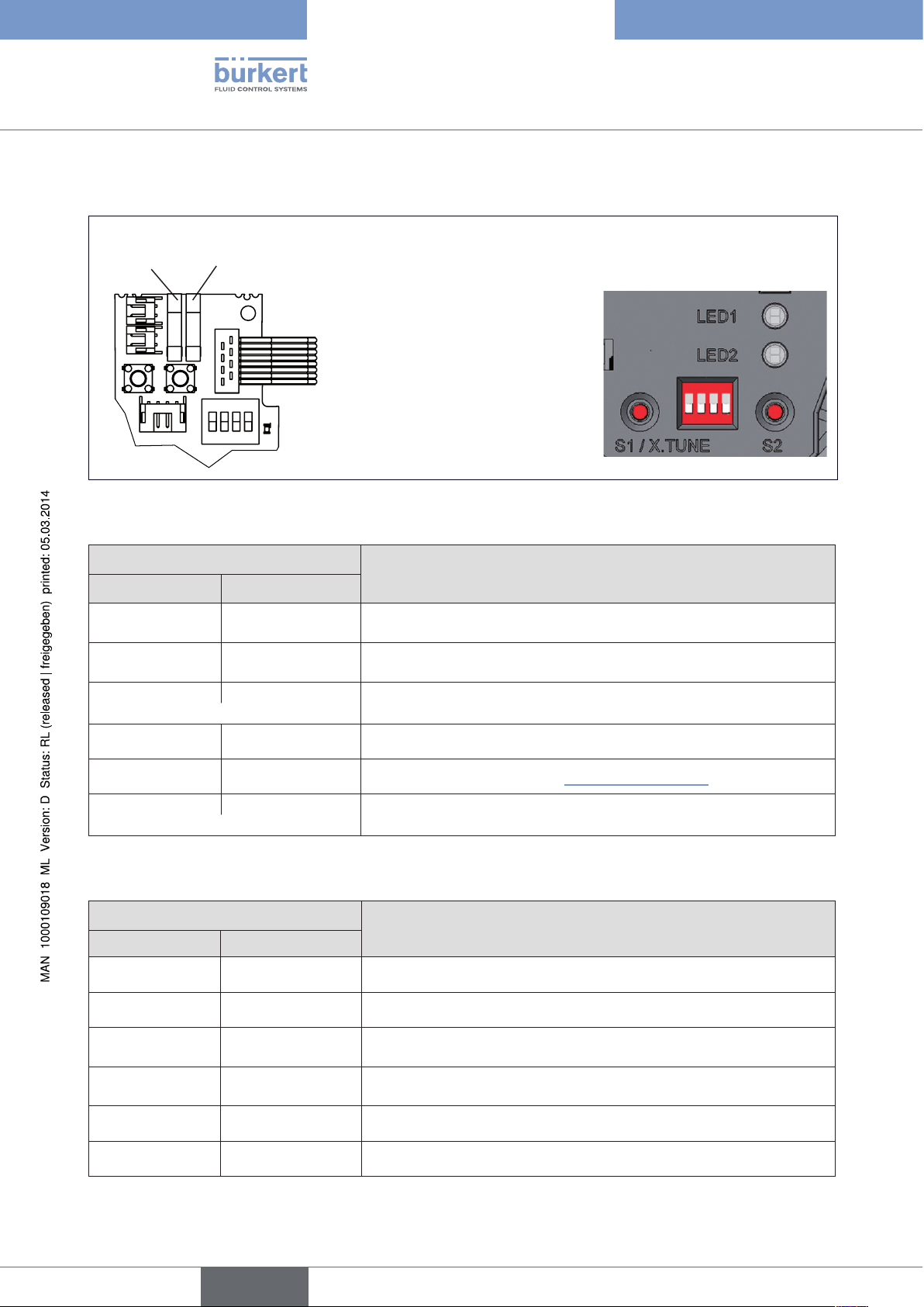
7.2. Control and display elements of the positioner
Version 1
LED 2LED 1
Key 1
Key 2
LED 2
DIP Switches
Version 2
Communications
interface
LED 1
24
Figure 8: Description of control elements
English
Communications
interface
Key 1
ON DIP
1 2 3 4
Key 2
Type 8694
Control and display elements
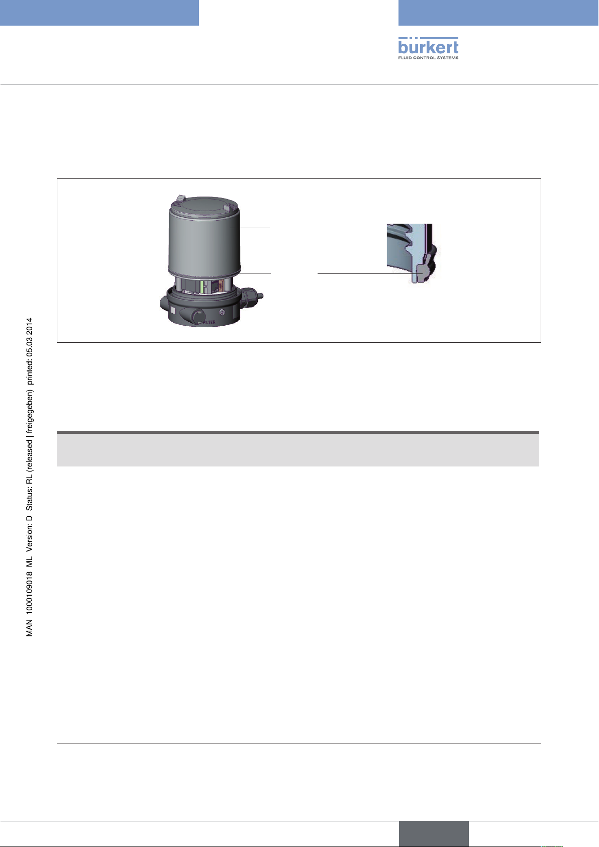
The positioner features 2 buttons, 4-pole DIP switches and 2x 2-colored LEDs as a display element.
→ To operate the buttons and DIP switches, for
Version 1: unscrew the body casing
Version 2: unscrew the transparent cap
Body casing
Seal
body casing
Figure 9: Position of the seal in the body casing
→ Version 1:
Check that the seal is correctly positioned in the body casing.
NOTE!
Damage or malfunction due to penetration of dirt and humidity!
• To observe protection class IP65 / IP67, screw the transparent cap in all the way.
→ Close the device (assembly tool: 674077
6)
).
6) The assembly tool (674077) is available from your Bürkert sales office.
25
English
Type 8694
Control and display elements
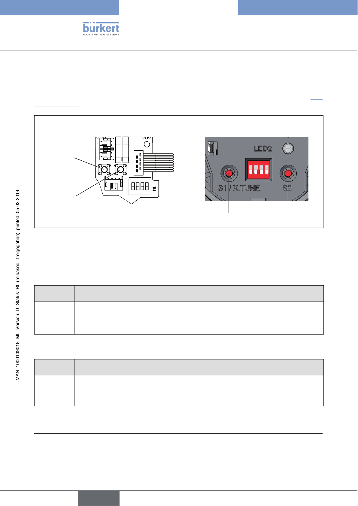
7.3. Configuration of the keys
The configuration of the 2 keys varies depending on the operating status (AUTOMATIC / MANUAL).
The description of the operating statuses (AUTOMATIC / MANUAL) can be found in the chapter entitled “7.1.
Operating status”.
Version 1 Version 2
Key 1
Key 2
Figure 10: Description of the buttons
→ To operate the buttons, for
Version 1: unscrew the body casing
Version 2: unscrew the transparent cap
MANUAL operating status (DIP switch 4 set to ON):
Key Function
7)
1
2
Table 6: Configuration of the keys for MANUAL operating status
Aerate
(manually open / close the actuator)
Deaerate7)
(manually open / close the actuator)
AUTOMATIC operating status (DIP switch 4 set to OFF):
Key Function
1 Press for 5 seconds to start the X.TUNE function
8)
8)
Key 1
Key 2
26
2 -
Table 7: Configuration of the keys for AUTOMATIC operating status
7)
No function if the binary input was activated with the “Manual/Auto change-over” via the communications
software
8) Depending on the operating principle of the actuator.
English

Type 8694
Control and display elements
Body casing
Seal
body casing
Figure 11: Position of the seal in the body casing
→ Version 1:
Check that the seal is correctly positioned in the body casing.
NOTE!
Damage or malfunction due to penetration of dirt and humidity!
• To observe protection class IP65 / IP67, screw the transparent cap in all the way.
→ Close the device (assembly tool: 674077
9)
).
9) The assembly tool (674077) is available from your Bürkert sales office.
27
English
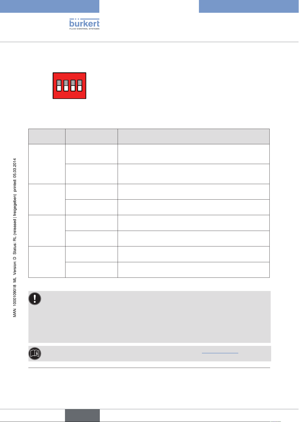
7.4. Function of the DIP switches
ON DIP
2 3 4
1
→ To operate the DIP switches, for
Version 1: unscrew the body casing
Version 2: unscrew the transparent cap
DIP Switches Position Function
1 ON Reversal of the effective direction of the set-point value (DIR.CMD)
(set-point value 20 – 4 mA corresponds to position 0 – 100 %),
descending
OFF Normal effective direction of the set-point value
(set-point value 4 – 20 mA corresponds to position 0 – 100 %),
ascending
2 ON Sealing function active. The valve completely closes below 2 %
opens above 98 % of the set-point value (CUTOFF)
Type 8694
Control and display elements
10)
and
OFF No sealing function
3 ON Correction characteristic for adjustment of the operating characteristic
(linearization of the process characteristic CHARACT)
11)
OFF Linear characteristic
4 ON Operating status MANUAL (BY HAND)
OFF Operating status AUTOMATIC (AUTO)
Table 8: DIP Switches
Information about the communications software:
The switching position of the DIP switch has priority over the settings via the communications software!
If the values of the sealing function (CUTOFF) or the correction characteristic (CHARACT) are changed
via the communications software, the corresponding function must be active (DIP switches set to ON).
The effective direction of the set-point value (DIR.CMD) can be changed via the DIP switches only.
If the correction characteristic (CHARACT) is not changed via the communications software, a linear characteristic is saved when DIP switch 3 is set to ON.
28
A detailed description of the functions can be found in the chapter entitled “Basic functions” and in the
operating instructions for the communications software.
10) Factory setting, can be changed via communications software.
11) The characteristic type can be changed via communications software
English
Type 8694
Control and display elements
Body casing
Seal
body casing
Figure 12: Position of the seal in the body casing
→ Version 1:
Check that the seal is correctly positioned in the body casing.
NOTE!
Damage or malfunction due to penetration of dirt and humidity!
• To observe protection class IP65 / IP67, screw the transparent cap in all the way.
→ Close the device (assembly tool: 674077
12)
).
12) The assembly tool (674077) is available from your Bürkert sales office.
29
English
7.5. Display of the LEDs
Version 1 Version 2
LED 1 LED 2
LED 1
(green /
red)
Display of mode
statuses
AUTO, MANUAL,
X.TUNE and FAULT
Type 8694
Control and display elements
LED 2
(green /
yellow)
Display of the actuator
status
(open, closed, opens
or closes)
Figure 13: LED display
LED 1 (green / red)
LED statuses
Display
green red
on off Acceleration phase when Power ON
flashes slowly off Operating status AUTO (AUTOMATIC)
flashing flashing MANUAL operating status
alternating
flashes quickly off X.TUNE function
off on
ERROR (see chapter entitled “7.6. Error messages”)
flashing flashing AUTO operating status for sensor break detection
slow
Table 9: Display LED 1
30
LED 2 (green / yellow)
LED statuses
Display
green yellow
on off Actuator closed
off on Actuator open
flashes slowly off
off flashes slowly
remaining control deviation
(actual value > set-point value)
remaining control deviation
(actual value < set-point value)
flashes quickly off Closing in MANUAL operating status
off flashes quickly Opening in MANUAL operating status
Table 10: Display LED 2
English
 Loading...