

Page 1

Recirculating Chiller F-100 / F-105
Operation Manual
11593840C en
Page 2

Imprint
Product Identification:
Operation Manual (Original), Recirculating Chiller F-100 / F-105
11593840C en
Publication date: 02.2016
BÜCHI Labortechnik AG
Meierseggstrasse 40
Postfach
CH-9230 Flawil 1
E-Mail: quality@buchi.com
BUCHI reserves the right to make changes to the manual as deemed necessary in the light of
experience; especially in respect to structure, illustrations and technical detail.
This manual is copyright. Information from it may not be reproduced, distributed, or used for
competitive purposes, nor made available to third parties. The manufacture of any component
with the aid of this manual without prior written agreement is also prohibited.
Page 3

Table of contents
3
F-100 / F-105 Operation Manual, Version C
Table of contents
1 About this manual . . . . . . . . . . . . . . . . . . . . . . . . . . . . . . . . . . . . . . .4
2 Safety. . . . . . . . . . . . . . . . . . . . . . . . . . . . . . . . . . . . . . . . . . . . . .5
2.1 User qualification . . . . . . . . . . . . . . . . . . . . . . . . . . . . . . . . . . . . 5
2.2 Proper use . . . . . . . . . . . . . . . . . . . . . . . . . . . . . . . . . . . . . . . 5
2.3 Improper use . . . . . . . . . . . . . . . . . . . . . . . . . . . . . . . . . . . . . . 5
2.4 Safety warnings and safety signs used in this manual . . . . . . . . . . . . . . . . . . 6
2.5 Product safety. . . . . . . . . . . . . . . . . . . . . . . . . . . . . . . . . . . . . .8
2.5.1 General hazards. . . . . . . . . . . . . . . . . . . . . . . . . . . . . . . . . . . . .8
2.5.2 Personal protective equipment . . . . . . . . . . . . . . . . . . . . . . . . . . . . . 9
2.5.3 Built-in safety elements and measures . . . . . . . . . . . . . . . . . . . . . . . . . 9
2.6 General safety rules . . . . . . . . . . . . . . . . . . . . . . . . . . . . . . . . . . 10
3 Technical data . . . . . . . . . . . . . . . . . . . . . . . . . . . . . . . . . . . . . . . . 11
3.1 Technical data . . . . . . . . . . . . . . . . . . . . . . . . . . . . . . . . . . . . 11
3.2 Materials used . . . . . . . . . . . . . . . . . . . . . . . . . . . . . . . . . . . . 12
4 Description of function . . . . . . . . . . . . . . . . . . . . . . . . . . . . . . . . . . . 13
4.1 Functional principle . . . . . . . . . . . . . . . . . . . . . . . . . . . . . . . . . 13
5 Putting into operation . . . . . . . . . . . . . . . . . . . . . . . . . . . . . . . . . . . . 15
5.1 Installation site . . . . . . . . . . . . . . . . . . . . . . . . . . . . . . . . . . . . 15
5.2 Electrical connections . . . . . . . . . . . . . . . . . . . . . . . . . . . . . . . . 17
6 Operation . . . . . . . . . . . . . . . . . . . . . . . . . . . . . . . . . . . . . . . . . . 18
6.1 Operating controls and housing . . . . . . . . . . . . . . . . . . . . . . . . . . . 18
6.2 Preparing for use . . . . . . . . . . . . . . . . . . . . . . . . . . . . . . . . . . 20
6.2.1 Installing the hoses . . . . . . . . . . . . . . . . . . . . . . . . . . . . . . . . . . 20
6.2.2 Filling the chiller . . . . . . . . . . . . . . . . . . . . . . . . . . . . . . . . . . . . 21
6.3 Start operation. . . . . . . . . . . . . . . . . . . . . . . . . . . . . . . . . . . . 21
6.4 No BUCHI vacuum controller connected to the system . . . . . . . . . . . . . . . 21
6.5 Working with BUCHI vacuum controller . . . . . . . . . . . . . . . . . . . . . . . 22
7 Maintenance and repairs . . . . . . . . . . . . . . . . . . . . . . . . . . . . . . . . . . 23
7.1 Customer service . . . . . . . . . . . . . . . . . . . . . . . . . . . . . . . . . . 23
7.2 General inspection and cleaning instructions. . . . . . . . . . . . . . . . . . . . . 24
8 Troubleshooting . . . . . . . . . . . . . . . . . . . . . . . . . . . . . . . . . . . . . . . 25
8.1 Error message display (only F-105) . . . . . . . . . . . . . . . . . . . . . . . . . 25
8.2 Malfunctions and their remedies. . . . . . . . . . . . . . . . . . . . . . . . . . . . 25
9 Shutdown, storage, transport and disposal . . . . . . . . . . . . . . . . . . . . . . . . 26
9.1 Storage and transport . . . . . . . . . . . . . . . . . . . . . . . . . . . . . . . . 26
9.2 Disposal . . . . . . . . . . . . . . . . . . . . . . . . . . . . . . . . . . . . . . . 27
10 Spare parts. . . . . . . . . . . . . . . . . . . . . . . . . . . . . . . . . . . . . . . . . . 29
10.1 Enclosed parts. . . . . . . . . . . . . . . . . . . . . . . . . . . . . . . . . . . . 29
10.2 Instrument configuration . . . . . . . . . . . . . . . . . . . . . . . . . . . . . . . 30
10.3 Spare parts, optional accessories . . . . . . . . . . . . . . . . . . . . . . . . . . 30
Page 4
1 About this manual
4
F-100 / F-105 Operation Manual, Version C
1 About this manual
This manual describes the Chiller and provides all information required for its safe operation and to
maintain it in good working order.
It is addressed to laboratory personnel and operators in particular.
Read this manual carefully before installing and running your system and note the safety precautions
in section 2 in particular. Store the manual in the immediate vicinity of the instrument, so that it can be
consulted at any time.
No technical modifications may be made to the instrument without the prior written agreement of
BUCHI. Unauthorized modifications may affect the system safety or result in accidents. Technical data
are subject to change without notice.
NOTE
The symbols pertaining to safety (WARNINGS and ATTENTIONS) are explained in section 2.
This manual is copyright. Information from it may not be reproduced, distributed or used for competitive purposes, nor made available to third parties. The manufacture of any component with the aid of
this manual without prior written agreement is also prohibited.
The German manual is the original language version and serves as basis for all translations into other
languages. If you need another language version of this manual, you can download available versions
at www.buchi.com or reorder manuals from a BUCHI representative.
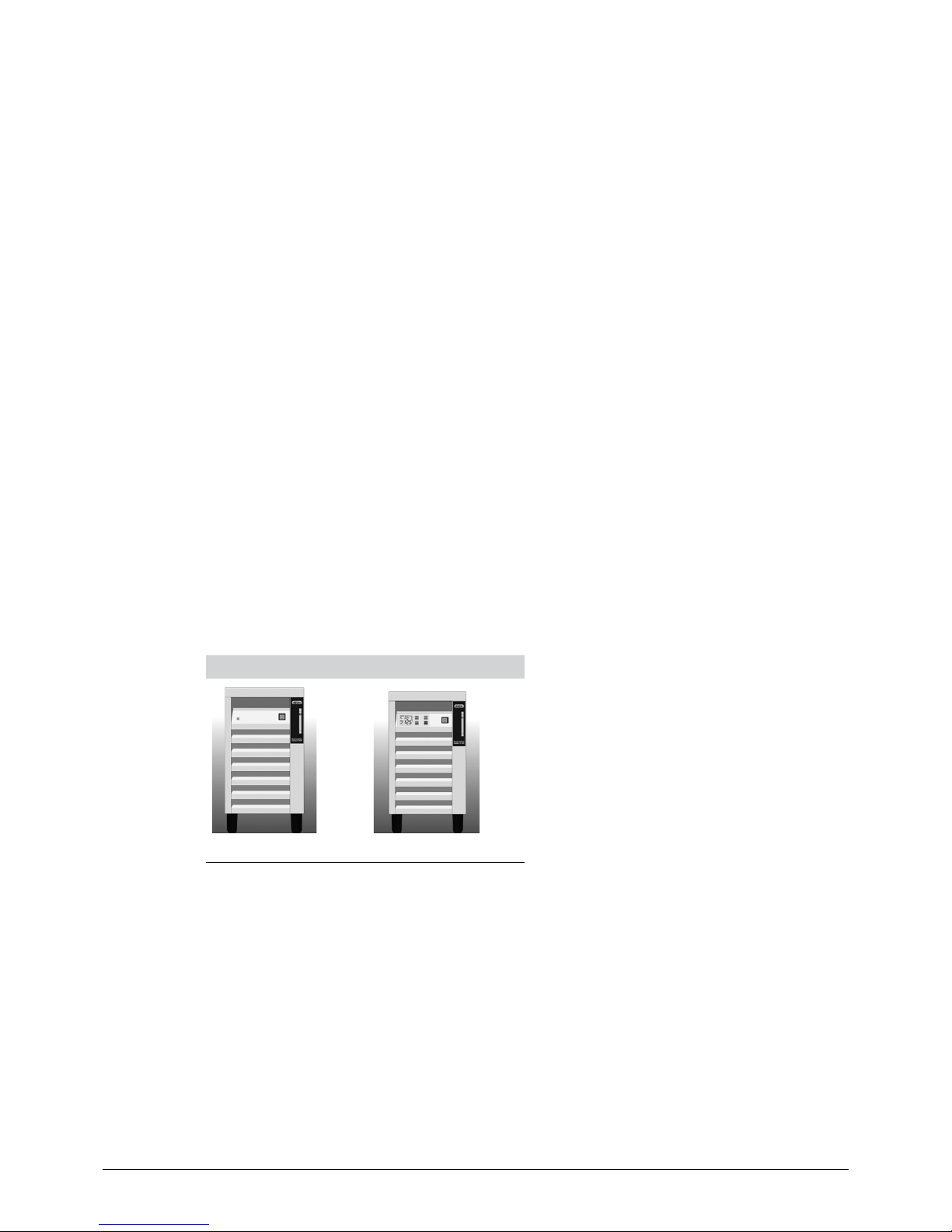
Recirculating Chiller – Types
F-100 F-105
Page 5

2 Safety
5
F-100 / F-105 Operation Manual, Version C
2 Safety
This section introduces the safety concept of the instrument and contains general rules of behavior
and warnings from direct and indirect hazards concerning the use of the product.
For the users safety, all safety instructions and safety messages in the individual sections shall
be strictly observed and followed. Therefore, the manual must always be available to all persons
performing any tasks described herein.
2.1 User qualification
The instrument may only be used by laboratory personnel and other persons who on account of
training and professional experience know the potential dangers that can develop when operating the
instrument.
Untrained personnel, or persons who are currently being trained, require careful supervision by a qualified person. This Operation Manual serves as a basis for training.
2.2 Proper use
The Recirculating Chiller is conceived and built as a piece of laboratory equipment. Its regulation use is
the cooling of closed cycles (e.g. rotary evaporators, reaction vessels).
When the Recirculating Chiller is used in combination with other instruments (e.g. rotary evaporator
and extraction unit) all related manuals are to be fully observed.
The regulation use of the Recirculating Chiller also includes its care.
2.3 Improper use
Any other use than the one stated above and any application that does not comply with the technical
data is considered to be improper use. Improper use can cause hazardous situations for the operator
and / or for the instrument and might cause consequential property damage.
The operator bears the sole risk for any damages or hazards caused by improper use!
In particular, the following uses must not be permitted
• Installation or use of the instrument in rooms, which require ex-protected instruments.
• The use of spare parts or accessories other than those mentioned in these operating instructions.
• The equipment may not be operated using combustible substances.
• It is not allowed to put anything on the top of the Recirculating Chiller.
Page 6
2 Safety
6
F-100 / F-105 Operation Manual, Version C
2.4 Safety warnings and safety signs used in this manual
DANGER, WARNING, CAUTION and NOTICE are standardized signal words for identifying levels of
hazards and risks related to personal injury and property damage. All signal words, which are related
to personal injury are accompanied by the general safety sign.
For your safety it is important to read and fully understand the table below with the different signal
words and their definitions!
Sign Signal word Definition Risk level
DANGER
Indicates a hazardous situation which, if not avoided, will result
in death or serious injury.
★★★★
WARNING
Indicates a hazardous situation which, if not avoided, could
result in death or serious injury.
★★★☆
CAUTION
Indicates a hazardous situation which, if not avoided, may result
in minor or moderate injury.
★★☆☆
no NOTICE
Indicates possible property damage, but no
practices related to personal injury.
★☆☆☆
(property damage only)
Supplementary safety information symbols may be placed in a rectangular panel on the left to the
signal word and the supplementary text (see example below).
Space for
supplementary
safety
information
symbols.
!
SIGNAL WORD
Supplementary text, describing the kind and level of hazard/risk seriousness.
• List of measures to avoid the described hazard or hazardous situation.
• …
• …
Table of supplementary safety information symbols
The reference list below incorporates all safety information symbols used in this manual and their
meaning.
Symbol Meaning
General warning
Electrical hazard
Heavy weight, avoid overexertion
Explosive gases, explosive environment
Page 7

2 Safety
7
F-100 / F-105 Operation Manual, Version C
Symbol Meaning
Fire hazard
Harmful to life forms
Hot item, hot surface
Device damage
Inhalation of substances
Chemical burns by corrosives
Cuts by sharp edges
Flooding
Wear laboratory coat
Wear protective goggles
Wear protective gloves
Page 8
2 Safety
8
F-100 / F-105 Operation Manual, Version C
Additional user information
Paragraphs starting with NOTE transport helpful information for working with the device/software or its
supplementaries. NOTEs are not related to any kind of hazard or damage (see following example).
NOTE
Useful tips for the easy operation of the instrument/software.
2.5 Product safety
The Recirculating Chiller has been designed and built in accordance with current state-of-the-art technology, at the time of development. Safety warnings in this manual (as described in section 2.4) serve
to make the user alert to, and avoid hazardous situations emanating from residual dangers by giving
appropriate counter measures.
However, risks to users, property and the environment can arise when the instrument is damaged,
used carelessly or improperly.
2.5.1 General hazards
The following safety messages show hazards of general kind which may occur when handling the
instrument. The user shall observe all listed counter measures in order to achieve and maintain the
lowest possible level of hazard.
Additional warning messages can be found whenever actions and situations described in this manual
are related to situational hazards.
!
DANGER
Death or serious injuries when used in explosive environments.
• Do not store or operate the instrument in explosive environments
• Remove all sources of ammable vapors
• Do not store chemicals in the vicinity of the device
!
CAUTION
Risk of minor or moderate cuts by sharp edges.
• Do not touch defective or broken glassware with bare hands
• Do not touch thin metal edges
NOTICE
Risk of instrument damage by liquids or mechanical shocks.
• Do not spill liquids over the instrument or its components
• Do not drop the instrument or its components
• Keep external vibrations away from the instrument
Page 9

2 Safety
9
F-100 / F-105 Operation Manual, Version C
Safety messages regarding Refrigerant R134a:
!
WARNING
Danger of injury and material damage due to overheating.
• Keep at a temperature not exceeding 45°C
!
WARNING
Danger of corrosion and poisoning through inhalation of the fumes.
• In case of re and/or explosion do not breathe fumes
!
CAUTION
If R134a escapes in the event of a fault..
• Avoid contact with skin and eyes
• Always wear safety goggles
• Always wear safety gloves
2.5.2 Personal protective equipment
Always wear personal protective equipment such as protective eye goggles and protective clothing.
The personal protective equipment must meet all requirements of all data sheets for the chemicals
used. These instructions are an important part of the Recirculating Chiller and must be made available
at all times to the operating personnel at the place where the equipment is deployed.
!
WARNING
Serious chemical burns by corrosives.
• Always wear protective goggles
• Always wear protective gloves
• Always wear laboratory coat
2.5.3 Built-in safety elements and measures
The instrument is fitted with a thermal overload protection for the compressor.
Page 10

2 Safety
10
F-100 / F-105 Operation Manual, Version C
2.6 General safety rules
Responsibility of the operator
The head of the laboratory is responsible for training his/her personnel.
The operator shall inform the manufacturer without delay of any safety-related incidents which might
occur during operation of the instrument or its accessories. Legal regulations, such as local, state and
federal laws applying to the instrument or its accessories must be strictly followed.
Duty of maintenance and care
The operator is responsible for the proper condition of instrument. This includes maintenance, service
and repair jobs that are performed on schedule by authorized personnel only.
Spare parts to be used
Use only genuine consumables and spare parts for maintenance to assure good system performance,
reliability and safety. Any modifications of spare parts or assemblies are only allowed with the prior
written permission of the manufacturer.
Modifications
Modifications to the instrument are only permitted after prior consultation and with the written approval
of the manufacturer. Modifications and upgrades shall only be carried out by an authorized BUCHI
technical engineer. The manufacturer will decline any claim resulting from unauthorized modifications.
Page 11
3 Technical data
11
F-100 / F-105 Operation Manual, Version C
3 Technical data
This section introduces the reader to the Recirculating Chiller and its specifications. It contains the
technical data, requirements and performance data.
3.1 Technical data
Technical data
F-100 F-105
Dimensions (W x H x D) 280 x 500 x 420 mm 280 x 500 x 420 mm
Weight 28 kg 30 kg
Power consumption (max.) 850 W 850 W
Supply voltage 230 VAC ±10%
115 VAC ± 10 %
230 VAC ±10%
115 VAC ± 10 %
Fuse
230 V
115 V
6.3 AT
8 AT
6.3 AT
8 AT
Frequency 50/60 Hz 50/60 Hz
Environmental conditions For indoor use only
- Temperature 5–35°C 5–35°C
- Altitude up to 2000 m
- Humidity Maximum relative humidity 80% for temperatures up to 31°C
decreasing linearly to 50% relative humidity at 40°C
Temperature display No display digital, resolution 0.1°C
Overvoltage category II II
Degree of protection IP20 IP20
Pollution degree 2 2
Cooling capacity at 15°C --- 530 W
Cooling capacity at 10°C 300 W 390 W
Cooling capacity at 0°C --- 120 W
Cooling capacity at -10°C --- 10 W
Refrigerant R134a R134a
Set temperature range x +10°C –10°C … +25°C
Temperature regulation accuracy ±2°C ±1°C
Tank volume 3 L 3 L
Tubing connection 8 mm (GL14) 8 mm (GL14)
Pump ow rate 2.5 L/min 2.5 L/min
Pump pressure (max.) 0.6 bar 0.6 bar
Page 12

3 Technical data
12
F-100 / F-105 Operation Manual, Version C
3.2 Materials used
Materials used
Component Material designation Material code Hazardous substances
Stainless steel, powder-coated with
polyester-epoxide
Housing 1.4301
–
Copper Internal pipes and
coolers
CU –
Polyester Foil PES –
Glass-ber-reinforced epoxy resin Circuit board –
Polyvinyl chloride Cable PVC –
R134a Refrigerant 1,1,1,2-tetrauoro-
ethane
Check MSDS
Page 13

4 Description of function
13
F-100 / F-105 Operation Manual, Version C
4 Description of function
This section explains the basic working principle of the Recirculating Chiller. It also shows how the
instrument is structured and provides a general functional description of its assemblies.
4.1 Functional principle
The BUCHI Recirculating Chillers are a closed-circuit cooler for use with appropriate laboratory instruments. The four models are distinguished by their outputs and control. The F-100 has a fixed cooling
temperature without display. The models F-105 to F-114 are equipped with a control unit and built
in display to regulate and indicate the actual and set value of the cooling temperature. The F-100 is
optimal for cooling one BUCHI Rotavapor system. The F-114 is sufficient for cooling up to two small
to medium Rotavapor systems (e.g. R-210).
Diagram F-100
3
2
1
4
5
6
1 Circulation pump
2 Container with cooling coil
3 Capillary
4 Filter dryer
5 Heat exchanger
6 Compressor
Page 14

4 Description of function
14
F-100 / F-105 Operation Manual, Version C
Diagram F-105
3
2
1
4
5
6
7
1 Circulation pump
2 Container with cooling coil
3 Thermostatic expansion valve
4 Filter dryer
5 Heat exchanger
6 Compressor
7 In-line valve
Page 15

5 Putting into operation
15
F-100 / F-105 Operation Manual, Version C
5 Putting into operation
This section describes how the instrument has to be installed. It also gives instructions for the initial
startup.
NOTE
Inspect the instrument for damage during unpacking. If necessary, prepare a status report immediately and inform customer and your local BUCHI representative. Keep the original packaging for
future transportation.
Also adhere to all instructions concerning transport as described in section 9.1, Storage and transport.
To move the instrument use the handle (as described in section 6.1, Operating controls and housing),
slightly lift the side of the instrument with the fix anti-slip foots and pull the instrument carefully by the
rollers.
5.1 Installation site
!
DANGER
Death or serious injuries when used in explosive environments.
• Do not store or operate the instrument in explosive environments
• Remove all sources of ammable vapors
• Do not store chemicals in the vicinity of the device
Put the instrument onto a clean, stable and horizontal surface. Consider the maximum product dimensions and weight. Obtain the environmental conditions as described in section 3.1, technical data.
Installation pre-requisites and installation steps:
• Do not place any objects in front of or behind the instrument.
• The instrument must have a clearance of 40cm between itself and the wall, both in front and
behind (sufficient cooling).
• Do not place containers, chemicals or other items behind the instrument.
• Do not place anything on top of the Recirculating Chiller.
NOTE
• After transport, wait at least 2 hours before switching on the chiller! Within this time the refrigerant
gathers in the compressor, avoiding damage of the compressor.
• To ensure that the power can be cut by unplugging in case of an emergency, the mains plug must
not be blocked by the instruments or any other items!
• Depending on the environmental conditions, condensation water at the cooling tubes and all other
cold surfaces of the instruments can collect!
Page 16

5 Putting into operation
16
F-100 / F-105 Operation Manual, Version C
!
WARNING
Stumbling or falling due to improper installation of the cables and hoses.
• The length of the cables and hoses should be kept as short as possible
• Absorb condensate water from tubes and all other cold surfaces
• If possible, avoid installing cables and hoses in aisle areas
• If installation of cables and hoses in aisle areas is unavoidable, use an adequate protective
pad in order to avoid the danger of stumbling and damage
!
WARNING
Fire hazard, damage to the instrument through overheating due to inadequate air circulation.
• Do not cover the instrument
• Minimum distance from other objects must be at least 40cm
!
CAUTION
Risk of minor or moderate injury due to the heavy weight of the instrument.
• Do not drop the instrument or its transport box
• Place the instrument on a stable, even and vibration-free surface
• Keep limbs out of crushing zone
!
CAUTION
Danger from falling objects due to inadequate stability.
• Do not place other objects or instruments on the Chiller
Page 17

5 Putting into operation
17
F-100 / F-105 Operation Manual, Version C
5.2 Electrical connections
Notice
Risk of instrument damage if mains supply is incorrect.
• External mains supply must meet the voltage given on the type plate
• Check for proper grounding
• Exchange defective cabling immediately
After the installation procedure has been completed successfully, the power plug of the Recirculating
Chiller can be connected to mains.
The used mains circuit has to:
• provide the voltage that is given on the type plate of the instrument.
• be able to handle the load of the connected instruments.
• be equipped with adequate fuses and electrical safety measures, in particular proper grounding.
See also technical data of all components regarding the different minimum system requirements!
NOTE
• Additional electrical safety measures such as residual current breakers may be necessary to
meet local laws and regulations!
• External power switches (e.g. emergency stop switches) must meet IEC 60947-1 and
IEC60947-3 requirements. Such devices must be clearly labeled and accessible at any time.
• External connections and extension lines must be provided with a grounded conductor lead
(3-pole couplings, cord or plug equipment). All electrical cables used must be suitable for the
required power rating.
5.3 Factors affecting chilling capacity
The available chilling capacity is dependent on various factors. The most important aspect to be
aware of is that the chilling capacity diminishes as the chilling temperature is lowered. In the case
of the F-105 it is approx. 600W at 20 °C and only around 50W at –5°C. The ambient temperature
has an effect as well. At room temperatures above 35 °C the chiller's air cooling may, depending on
chilling capacity, no longer be sufficient and the chiller may switch off for safety reasons to protect
itself against overheating. At an ambient temperature of 30°C the F-105 still has a chilling capacity
of around 150–W. We recommended a chilling temperature setting of 10–15 °C and a room temperature that does not exceed 25 °C. Outside of those parameters, the chilling capacity is substantially
reduced.
Page 18

6 Operation
18
F-100 / F-105 Operation Manual, Version C
6 Operation
This section gives examples of typical instrument applications and instructions on how to operate the
instrument properly and safely. See also section 2.5 “Product safety” for general warnings.
6.1 Operating controls and housing
Front side
8
1
5
7
3
2
4
6
1 Opening for cooling medium
2 Handle (to pull the instrument)
3 On-/Off switch (lights green when instrument is
switched on)
4 Cooling media level indicator
5 Cooling lamella for air ow in
6 Wheels (not lockable)
7 Fix anti-slip feet
8 Operating panel with various parameter
displays (not available on the F-100)
Buttons (not for F-100)
Button Functionality
UP
Increase the desired set temperature in steps of 0.1°C.
DOWN
Decrease the desired set temperature in steps of 0.1°C.
START
Button to start or continue the cooling regulation.
Page 19

6 Operation
19
F-100 / F-105 Operation Manual, Version C
STOP
Button to stop the cooling regulation.
Display (not for F-100)
1
3
4
2
1 Set temperature of Recirculating Chiller in °C
2 Actual temperature of Recirculating Chiller in °C
3 Active cooling is indicated by the snow ake
4 If the Recirculating Chiller is connected to the
BUCHI vacuum controller the connection symbol
is displayed
Level indicator
2
3
1
1 Lower black line: minimum lling level
2 Upper black line: maximum lling level
3 Ball oat: actual ll level of coolant
Page 20

6 Operation
20
F-100 / F-105 Operation Manual, Version C
Rear side
1
8
2
7
5
6
3
4
1 Cooling medium ow in
2 Cooling medium ow out
3 Power socket
4 Communication cable socket, RS485
(not available for F-100 models)
5 Fuse
6 Slots for air ow out
7 Antistatic wheels (not lockable)
8 Drainvalve, to empty the cooling medium tank
6.2 Preparing for use
Prerequisites
• All parts must be clean and free of damage.
• Close the drainvalve.
6.2.1 Installing the hoses
!
WARNING
Stumbling or falling due to improper installation of the cables and hoses.
• The length of the cables and hoses should be kept as short as possible
• If possible, avoid installing cables and hoses in aisle areas
• If installation of cables and hoses in aisle areas is unavoidable, use an adequate protective
pad in order to avoid the danger of stumbling and damage
• Connect out flow and return flow connections of the Recirculating Chiller with the condenser of the
rotary evaporator.
NOTE
Only use hoses which can withstand min. –10°C and 2bar pressure and secure them with the usual
hose clamps.
• Connect Chiller outlet (OUT) to the second condenser installed on the pump.
• Connect the outlet of the second condenser to the Rotavapor® Condenser.
• Connect the outlet of the Rotavapor® Condenser to the inlet (IN) of the Recirculating Chiller.
Page 21

6 Operation
21
F-100 / F-105 Operation Manual, Version C
6.2.2 Filling the chiller
NOTICE
Risk of instrument damage if wrong cooling medium is used.
• Check to ensure that the cooling medium is suitable for use at the desired cooling temperature and does not freeze at the working temperature
Fill the cooling liquid in the opening to maximum filling level while the chiller is not connected to
another device. We recommend a mixture of ethylene glycol/water at least 40/60, which does not
freeze until –16°C.
6.3 Start operation
NOTE
See installation instructions (chapter 5.1) for initial startup!
!
WARNING
Danger of injury due to tipping or failure of the instrument due to vibrations.
• After being transported, the recirculating chiller must be allowed to stand for at least 2 hour
before it is switched on.
Start the Recirculating Chiller by switching on the Instrument by the main switch. Press start on the
Chiller to fill the cooling coils.
6.4 No BUCHI vacuum controller connected to the system
Preparational steps
• System must be in good working order. See final installation check, section 5.1.
• Turn on instrument.
• Check level of cooling transfer medium as described in section 6.1 Level indicator.
• Set the desired working temperature by the UP and DOWN buttons (not for F-100).
• Press the START button to start the cooling process (not for F-100).
• Check the actual temperature on the Chiller until it has reached the required temperature and start
working.
Working steps
• The cooling temperature can be adjusted during the operation process by pressing the UP and
DOWN buttons on the Chiller (not for F-100).
• If the Chiller can’t keep the required temperature, do a slower distillation, by means of decreasing
the vacuum to a slightly higher level so that less vapour is coming to the cooling coil.
Steps for end of process
• Press the STOP button on the Chiller.
➡ The cooling stops immediately.
➡ After a few seconds ventilation also stops.
Page 22

6 Operation
22
F-100 / F-105 Operation Manual, Version C
6.5 Working with BUCHI vacuum controller
The Chiller model F-105 is equipped with a communication socket. Here, a BUCHI Rotavapor setup
or other appropriate laboratory instruments equipped with a BUCHI vacuum controller (model V-850
or higher with firmware version 3.0 or higher) can be attached.
To establish communication switch on all connected devices. After bootup time the UP and DOWN
buttons of the Chillers operation panel are blocked – the Chiller can be controlled via the Vacuum
Controller buttons.
*click*
To Rotavapor /
Vacuum pump
≤ 5m
NOTE
Do not exceed max. recommended cable length (5 m). For more information about operation see
respective manual of the Vacuum Controller in use.
Communication F-105
Vacuum Controller
V-850 or V-855
Interface I-100 Interface I-300 with
Legacy box
Start or stop chiller via controller or interface Yes Yes Ye s
Display set point and current temperature Yes No Yes
Adjust set point via controller or interface Yes No Yes
Page 23

7 Maintenance and repairs
23
F-100 / F-105 Operation Manual, Version C
7 Maintenance and repairs
This section gives instructions on maintenance work to be performed in order to keep the instrument in a good and safe working condition. All maintenance and repair work requiring the opening or
removal of the instrument housing must be carried out by trained BUCHI service personnel and only
with the tools provided for this purpose.
!
WARNING
Death or serious burns by electric current.
• Switch off the instrument, disconnect the power cord and prevent unintentional restart before
touching any of the elements inside the Recirculating Chiller
• Do not spill liquids over the device
NOTICE
Risk of housing and instrument damage by liquids and detergents.
• Use only ethanol or soapy water for cleaning
NOTE
Use only genuine consumables and spare parts for any maintenance and repair work in order to
assure warranty and continued system performance. Any modifications of the Recirculating Chiller or
parts of it require the prior written permission of the manufacturer.
7.1 Customer service
Only authorized service personnel are allowed to open up the housing and /or perform repair work on
the instrument which is not described in this manual. Authorization requires a comprehensive technical
training and knowledge of possible dangers which might arise when working at the instrument. Such
training and knowledge can only be provided by BUCHI.
Addresses of official BUCHI customer service offices are given on the BUCHI website under:
www.buchi.com. If malfunctions occur on your instrument or you have technical questions or application problems, contact one of these offices.
The customer service offers the following:
• Spare part delivery
• Repairs
• Technical advice
Page 24

7 Maintenance and repairs
24
F-100 / F-105 Operation Manual, Version C
7.2 General inspection and cleaning instructions
Check the housing for visible defects (switches, plugs, enclosure etc.) and clean it regularly under
safe conditions with a damp cloth. Wipe off any splashes of aggressive chemicals immediately using
a damp cloth in order to avoid any damage being caused to the coating on the housing. Ethanol as a
cleaning agent is also possible to use.
Cleaning under safe conditions
• Switch off the Recirculating Chiller and unplug the power cord.
➡ Let the system reach ambient temperature completely!
• Perform cleaning actions with a damp cloth.
• Regularly clean lamella with a damp cloth to remove dust, at least once a year.
Hoses
• Check the hoses for wear at least every six months.
• Exchange damaged hoses.
Cooling media tank
• Check before prior use the filling level of the Recirculating Chiller
• Exchange the cooling liquid once a year by means of the drainvalve and renew.
Page 25

8 Troubleshooting
25
F-100 / F-105 Operation Manual, Version C
8 Troubleshooting
This section helps to resume operation after a problem has occurred with the instrument which does
not require special technical training. It lists possible occurrences, their probable causes and suggests
how to remedy the problem.
8.1 Error message display (only F-105)
2
1
1 For every error the triangle lights.
2 The error number is indicated on the
display.
8.2 Malfunctions and their remedies
The troubleshooting table below lists possible malfunctions and errors of the instrument. The operator
is enabled to correct some of those problems or errors by him/herself. For this, appropriate corrective
measures are listed in the column “Remedy”.
Malfunctions and their remedies
Error Code Problem Remedy
E01 Temperature fault
Temperature sensor circuit break
Switch off the unit, and restart.
Call service if the problem persists.
E04 Pressure fault of the compressor Switch off the unit, let it cool down the compressor.
Call service to check the system if the problem persists.
E05 Data fault Switch off the unit and restart.
Call service if the problem persists.
E06 Temperature fault in the electronics Switch off the unit, let it cool down, clean air inlet and restart.
Call service if the problem persists.
Problem Remedy
F-100 / F-105 does not work Switch off the unit and unplug the
power cord.
Change the fuse according to technical
data and restart.
Call service if the problem persists.
1
1 Fuse
Page 26

9 Shutdown, storage, transport and disposal
26
F-100 / F-105 Operation Manual, Version C
9 Shutdown, storage, transport and disposal
!
WARNING
Poisoning or serious injuries through contact with or incorporation of harmful substances.
• Wear safety goggles
• Wear safety gloves
• Wear a laboratory coat
• Clean the instrument and all accessories thoroughly to remove possibly dangerous substances
• Do not clean dusty parts with compressed air
• Store the instrument and its accessories in a dry place in the original packaging
This section instructs how to shut down and pack the instrument for storage or transport. Specifications for storage and shipping conditions can also be found listed here.
NOTE
See manufacturer safety data sheet (chapter 11) about the refrigerant!
9.1 Storage and transport
NOTICE
Defective instrument due to improper packaging or improper transport.
• Pack the instrument for safe transport with new, suitable packaging material
• In particular, secure the compressor for transport
• Secure the properly packaged instrument on a pallet for transport
Switch off the instrument and remove the power cord. To disassemble the Recirculating Chiller follow
the installation instructions in section 5 in reverse order. Clean the instrument thoroughly! The cooling
liquid is to be drained before storage or shipping. The instrument is to be stored in the original packaging in a dry location. Shipping is also to be done in the original packaging and in upright position
only.
NOTE
• After transport, wait at least 2 hours before switching on the chiller! Within this time the refrig-
erant gathers in the compressor, avoiding damage of the compressor.
• Completely drain off coolant fluid (tilt appliance slightly if necessary). Then turn off the drain tap.
Page 27

9 Shutdown, storage, transport and disposal
27
F-100 / F-105 Operation Manual, Version C
9.2 Disposal
!
CAUTION
Freeze-burns and eye injuries through direct contact with R134a.
• Avoid contact with skin and eyes
• Always wear safety goggles
• Always wear safety gloves
• Hoses can be additionally insulated (see optional offering for hose insulation)
Disposal of instrument
For instrument disposal in an environmentally friendly manner, a list of materials is given in section 3.2.
This helps to ensure that the components can be separated and recycled correctly by a specialist for
disposal.
You have to follow valid regional and local laws concerning disposal. For help, please contact your
local authorities!
NOTE
When returning the instrument to the manufacturer for repair work, please copy and complete the
health and safety clearance form on the following page and enclose it with the instrument.
Disposal of Refrigerant R134a
The cooling medium R134a must be destroyed in an approved facility, which is equipped to absorb
and neutralize acidic gases and other toxic processing products.
Page 28

Health and Safety Clearance
Health and Safety Clearance_20081110_KESS.doc_20081110 Version 1.0 Page 1/1
Declaration concerning safety, potential hazards and safe disposal of waste.
For the safety and health of our staff, laws and regulations regarding the handling of
dangerous goods, occupational health and safety regulations, safety at work laws and
regulations regarding safe disposal of waste (e.g. chemical waste, chemical residues
or solvents) require that this form must be completed, signed and enclosed to every
return shipment of equipment or defective parts.
Instruments or parts will not be accepted if this declaration is not present.
Equipment
Model: Part/Instrument no.:
1.A Declaration for non dangerous goods
We assure that the returned equipment:
is unused and new.
has not been exposed to toxic, corrosive, biologically active, explosive, radioactive
or other dangerous matters. No hazard emanates from the device!
is free of contamination (e.g.that chemicals, solvents or residues of pumped media
have been drained prior to shipment). No hazard emanates from the device!
1.B Declaration for dangerous goods
Exhaustive list of dangerous substances the equipment has been exposed to:
Chemical, substance Danger classification
We assure that:
all hazardous substances (e.g. toxic, corrosive, biologically active, explosive,
radioactive etc.) which have been processed or been in contact with the equipment
are listed above.
the equipment has been cleaned, decontaminated and is free of transmissible
agents such as hazardous fungi, bacteria, viruses etc. If sterilization is applicable,
all in- and outlets of the equipment have been properly sealed the process.
2. Final Declaration
We hereby declare that:
- we know all about the substances which have been in contact with the equipment
and all questions have been answered correctly.
- we have taken all measures to prevent potential risks that might emanate from the
delivered equipment.
- this document will be attached clearly visible and securely to the outside of the
transport box.
Company name or stamp:
Place, date:
Name (print), job title (print):
Signature:
Page 29

10 Spare parts
29
F-100 / F-105 Operation Manual, Version C
10 Spare parts
This section lists spare parts, accessories and options including their ordering information.
Only order spare parts and consumables from BUCHI to maintain the warranty status and to assure
best performance and reliability of the system and affected components. Any modifications to the
spare parts used are only allowed with the prior written permission of the manufacturer.
Always state the product designation, instrument serial and part numbers for warranty clearance when
ordering spare parts!
10.1 Enclosed parts
Enclosed parts matrix
F-100 F-105
Mains cables
✓ ✓
Control cable RJ45,
2m
— ✓
Hose D6/9 2m,
2×
✓ ✓
Hose nipple 8mm,
4×
✓ ✓
Screw cap GL14,
4×
✓ ✓
Hose clamp 9.9mm,
4×
✓ ✓
Operation Manual
✓ ✓
Page 30

10 Spare parts
30
F-100 / F-105 Operation Manual, Version C
10.2 Instrument configuration
Content
Instrument versions:
BUCHI Recirculating Chiller
Order no.
F-1XX 230 V
F-100 Model 300 Watt x at 10°C 11060000
F-105 Model 500 Watt controlled 11060002
F-1XX 115 V
F-100 Model 300 Watt x at 10°C 11056461
F-105 Model 500 Watt controlled 11056463
10.3 Spare parts, optional accessories
Example
Spare parts
Description Order no.
Power cable 3 pin, type CH 010010
Power cable 3 pin, type SCHUKO 010016
Power cable 3 pin, type GB 017835
Power cable 3 pin, type AU 017836
Power cable, 3 pin, type US 010020
Power cable, 3 pin, type IND 11060536
Ethernet cable, 2m, RJ45 Cat. 5e, gray 044989
Cable RJ45, 5 m 11056240
Tubing, silicone, 6/9 mm, 1m, transparent (F-100, F-105)
04133
Page 31

10 Spare parts
31
F-100 / F-105 Operation Manual, Version C
Set of hose barbs, GL14
olive bent (4 pcs), cap nut (4 pcs)
037287
Hose clamp 9.9 mm 027738
Insulation hose for silicone hose,
Kaiex, 11/23 mm, 1m, black
28696
Y piece tubing coupling, 8 mm 011043
Quick-t coupling, 12 mm
set of 2 pieces
042885
Page 32

Page 33

Page 34

Quality in your hands
BUCHI Affiliates:
We are represented by more than 100 distribution partners worldwide.
Find your local representative at: www.buchi.com
BUCHI Support Centers:
Europe
Switzerland/Austria
BÜCHI Labortechnik AG
CH – 9230 Flawil
T +41 71 394 63 63
F +41 71 394 65 65
buchi@buchi.com
www.buchi.com
Benelux
BÜCHI Labortechnik GmbH
Branch Offi ce Benelux
NL – 3342 GT Hendrik-Ido-Ambacht
T +31 78 684 94 29
F +31 78 684 94 30
benelux@buchi.com
www.buchi.be
France
BUCHI Sarl
FR – 94656 Rungis Cedex
T +33 1 56 70 62 50
F +33 1 46 86 00 31
france@buchi.com
www.buchi.fr
Germany
BÜCHI Labortechnik GmbH
DE – 45127 Essen
T +800 414 0 414 0 (Toll Free)
T +49 201 747 49 0
F +49 201 747 49 20
deutschland@buchi.com
www.buechigmbh.de
Italy
BUCHI Italia s.r.l.
IT – 20010 Cornaredo (MI)
T +39 02 824 50 11
F +39 02 575 12 855
italia@buchi.com
www.buchi.it
Russia
BUCHI Russia/CIS
Russia 127287 Moscow
T +7 495 36 36 495
F +7 495 98 10 520
russia@buchi.com
www.buchi.ru
United Kingdom
BUCHI UK Ltd.
GB – Oldham OL9 9QL
T +44 161 633 1000
F +44 161 633 1007
uk@buchi.com
www.buchi.co.uk
Germany
BÜCHI NIR-Online
DE – 69190 Walldor f
T +49 6227 73 26 60
F +49 6227 73 26 70
nir-online@buchi.com
www.nir-online.de
China
BUCHI China
CN – 200052 Shanghai
T +86 21 6280 3366
F +86 21 5230 8821
china@buchi.com
www.buchi.com.cn
India
BUCHI India Private Ltd.
IN – Mumbai 400 055
T +91 22 667 75400
F +91 22 667 18986
india@buchi.com
www.buchi.in
Indonesia
PT. BUCHI Indonesia
ID – Tangerang 15321
T +62 21 537 62 16
F +62 21 537 62 17
indonesia@buchi.com
www.buchi.co.id
Japan
Nihon BUCHI K.K.
JP – Tokyo 110-0008
T +81 3 3821 4777
F +81 3 3821 4555
nihon@buchi.com
www.nihon-buchi.jp
Korea
BUCHI Korea Inc.
KR – Seoul 153-782
T +82 2 6718 7500
F +82 2 6718 7599
korea@buchi.com
www.buchi.kr
Malaysia
BUCHI Malaysia Sdn. Bhd.
MY – 47301 Petaling Jaya,
Selangor
T +60 3 7832 0310
F +60 3 7832 0309
malaysia@buchi.com
www.buchi.com
Singapore
BUCHI Singapore Pte. Ltd.
SG – Singapore 609919
T +65 6565 1175
F +65 6566 7047
singapore@buchi.com
www.buchi.com
Thailand
BUCHI (Thailand) Ltd.
TH – Bangkok 10600
T +66 2 862 08 51
F +66 2 862 08 54
thailand@buchi.com
www.buchi.co.th
Asia
America
Brazil
BUCHI Brasil Ltda.
BR – Valinhos SP 13271-200
T +55 19 3849 1201
F +55 19 3849 2907
brasil@buchi.com
www.buchi.com
USA/Canada
BUCHI Corporation
US – New Castle, DE 19720
T +1 877 692 8244 (Toll Free)
T +1 302 652 3000
F +1 302 652 8777
us-sales@buchi.com
www.mybuchi.com
South East Asia
BUCHI (Thailand) Ltd.
TH-Bangkok 10600
T +66 2 862 08 51
F +66 2 862 08 54
bacc@buchi.com
www.buchi.com
Middle East
BÜCHI Labortechnik AG
UAE – Dubai
T +971 4 313 2860
F +971 4 313 2861
middleeast@buchi.com
www.buchi.com
Latin America
BUCHI Latinoamérica Ltda.
BR – Valinhos SP 13271-200
T +55 19 3849 1201
F +55 19 3849 2907
latinoamerica@buchi.com
www.buchi.com
 Loading...