

Page 1

Encapsulator B-390
Operation Manual
11593477E en
Page 2

Imprint
Product Identification:
Operation Manual (Original), Encapsulator B-390
11593477E en
Publication date: 05.2016
BÜCHI Labortechnik AG
Meierseggstrasse 40
Postfach
CH-9230 Flawil 1
E-Mail: quality@buchi.com
BUCHI reserves the right to make changes to the manual as deemed necessary in the light of experience; especially in respect to structure, illustrations and technical detail.
This manual is copyright. Information from it may not be reproduced, distributed, or used for competitive purposes, nor made available to third parties. The manufacture of any component with the aid of this manual without
prior written agreement is also prohibited.
Page 3

Table of contents
3
B-390 Operation Manual, Version E
Read this manual carefully before installing and running your system and note the safety precautions
in chapter 2 in particular. Store the manual in the immediate vicinity of the instrument, so that it can be
consulted at any time.
No technical modifications may be made to the instrument without the prior written agreement of
BUCHI. Unauthorized modifications may affect the system safety, the EU conformity or result in accidents.
This manual is copyright. Information from it may not be reproduced, distributed, or used for competitive purposes, nor made available to third parties. The manufacture of any component with the aid of
this manual without prior written agreement is also prohibited.
The English manual is the original language version and serves as basis for all translations
into other languages.
Table of contents
1 About this manual . . . . . . . . . . . . . . . . . . . . . . . . . . . . . . . . . . . . . . .5
2 Safety. . . . . . . . . . . . . . . . . . . . . . . . . . . . . . . . . . . . . . . . . . . . . .6
2.1 User qualification . . . . . . . . . . . . . . . . . . . . . . . . . . . . . . . . . . . . 6
2.2 Proper use . . . . . . . . . . . . . . . . . . . . . . . . . . . . . . . . . . . . . . . 6
2.3 Improper use . . . . . . . . . . . . . . . . . . . . . . . . . . . . . . . . . . . . . . 6
2.4 Safety warnings and safety signals used in this manual . . . . . . . . . . . . . . . . . 7
2.5 Product safety. . . . . . . . . . . . . . . . . . . . . . . . . . . . . . . . . . . . . .9
2.5.1 General hazards. . . . . . . . . . . . . . . . . . . . . . . . . . . . . . . . . . . . .9
2.5.2 Safety measures . . . . . . . . . . . . . . . . . . . . . . . . . . . . . . . . . . . 10
2.5.3 Built-in safety elements and measures . . . . . . . . . . . . . . . . . . . . . . . . 10
2.6 General safety rules . . . . . . . . . . . . . . . . . . . . . . . . . . . . . . . . . . 11
2.7 Disclaimer . . . . . . . . . . . . . . . . . . . . . . . . . . . . . . . . . . . . . . . 11
3 Technical data . . . . . . . . . . . . . . . . . . . . . . . . . . . . . . . . . . . . . . . . 12
3.1 Scope of application and delivery . . . . . . . . . . . . . . . . . . . . . . . . . . . 12
3.1.1 Standard instrument. . . . . . . . . . . . . . . . . . . . . . . . . . . . . . . . . . 12
3.1.2 Standard accessories . . . . . . . . . . . . . . . . . . . . . . . . . . . . . . . . . 13
3.1.3 Optional accessories . . . . . . . . . . . . . . . . . . . . . . . . . . . . . . . . . 13
3.1.4 Recommended spare parts . . . . . . . . . . . . . . . . . . . . . . . . . . . . . . 14
3.2 Technical data . . . . . . . . . . . . . . . . . . . . . . . . . . . . . . . . . . . . . 15
3.3 Materials used. . . . . . . . . . . . . . . . . . . . . . . . . . . . . . . . . . . . . 15
4 Description of function . . . . . . . . . . . . . . . . . . . . . . . . . . . . . . . . . . . 16
4.1 Functional principle . . . . . . . . . . . . . . . . . . . . . . . . . . . . . . . . . . 16
4.2 Connections at the Encapsulator B-390. . . . . . . . . . . . . . . . . . . . . . . . 18
5 Putting into operation . . . . . . . . . . . . . . . . . . . . . . . . . . . . . . . . . . . . 19
5.1 Installation site. . . . . . . . . . . . . . . . . . . . . . . . . . . . . . . . . . . . . 19
5.2 Installing the Encapsulator B-390 . . . . . . . . . . . . . . . . . . . . . . . . . . . 20
5.3 Electrical connections . . . . . . . . . . . . . . . . . . . . . . . . . . . . . . . . . 21
5.4 Assembling of the bead producing unit . . . . . . . . . . . . . . . . . . . . . . . . 22
5.5 Single (inner) nozzles . . . . . . . . . . . . . . . . . . . . . . . . . . . . . . . . . 22
5.6 Electrode . . . . . . . . . . . . . . . . . . . . . . . . . . . . . . . . . . . . . . . 23
5.7 Pressure bottle . . . . . . . . . . . . . . . . . . . . . . . . . . . . . . . . . . . . 25
5.7.1 Installation of the pressure bottle . . . . . . . . . . . . . . . . . . . . . . . . . . . 26
5.8 Option: Concentric nozzle system . . . . . . . . . . . . . . . . . . . . . . . . . . . 27
5.8.1 Mounting of CN nozzles . . . . . . . . . . . . . . . . . . . . . . . . . . . . . . . . 29
5.9 Final installation check. . . . . . . . . . . . . . . . . . . . . . . . . . . . . . . . . 30
Page 4

Table of contents
4
B-390 Operation Manual, Version E
6 Operation . . . . . . . . . . . . . . . . . . . . . . . . . . . . . . . . . . . . . . . . . . 31
6.1 Starting up the instrument . . . . . . . . . . . . . . . . . . . . . . . . . . . . . . . 31
6.2 Screens and menu functions . . . . . . . . . . . . . . . . . . . . . . . . . . . . . 31
6.3 Menu structure of the control unit . . . . . . . . . . . . . . . . . . . . . . . . . . . 33
6.4 Manual air pressure control . . . . . . . . . . . . . . . . . . . . . . . . . . . . . . 34
6.5 Practicing with the Encapsulator, using water . . . . . . . . . . . . . . . . . . . . . 35
6.6 Practicing with the Encapsulator, using alginate solution. . . . . . . . . . . . . . . . 38
6.6.1 Preparation of 1.5 % Na-alginate solution . . . . . . . . . . . . . . . . . . . . . . . 38
6.6.2 Working with alginate solution . . . . . . . . . . . . . . . . . . . . . . . . . . . . . 39
6.7 Theoretical background . . . . . . . . . . . . . . . . . . . . . . . . . . . . . . . . 41
6.7.1 Bead productivity and cell density . . . . . . . . . . . . . . . . . . . . . . . . . . . 43
7 Maintenance and repairs . . . . . . . . . . . . . . . . . . . . . . . . . . . . . . . . . . 46
7.1 Customer service . . . . . . . . . . . . . . . . . . . . . . . . . . . . . . . . . . . 46
7.2 Housing condition . . . . . . . . . . . . . . . . . . . . . . . . . . . . . . . . . . . 46
7.3 Sealing conditions . . . . . . . . . . . . . . . . . . . . . . . . . . . . . . . . . . . 46
7.4 Cleaning. . . . . . . . . . . . . . . . . . . . . . . . . . . . . . . . . . . . . . . . 47
7.4.1 Cleaning the nozzle after each immobilization run . . . . . . . . . . . . . . . . . . . 47
7.4.2 Cleaning a clogged nozzle. . . . . . . . . . . . . . . . . . . . . . . . . . . . . . . 48
7.4.3 Cleaning the bead producing unit . . . . . . . . . . . . . . . . . . . . . . . . . . . 48
8 Troubleshooting . . . . . . . . . . . . . . . . . . . . . . . . . . . . . . . . . . . . . . . 49
8.1 Malfunctions and their remedy. . . . . . . . . . . . . . . . . . . . . . . . . . . . . 49
9 Shutdown, storage, transport and disposal . . . . . . . . . . . . . . . . . . . . . . . . 50
9.1 Storage and transport . . . . . . . . . . . . . . . . . . . . . . . . . . . . . . . . . 50
9.2 Disposal. . . . . . . . . . . . . . . . . . . . . . . . . . . . . . . . . . . . . . . . 51
10 Declarations and requirements. . . . . . . . . . . . . . . . . . . . . . . . . . . . . . . 52
10.1 FCC requirements (for USA and Canada) . . . . . . . . . . . . . . . . . . . . . . . 52
10.2 Health and Safety Clearance form . . . . . . . . . . . . . . . . . . . . . . . . . . . 53
Page 5

1 About this manual
5
B-390 Operation Manual, Version E
1 About this manual
This manual describes the Encapsulator B-390. It provides all information required for its safe operation and to maintain it in good working order. It is addressed to laboratory personnel in particular.
If the instrument is used in a manner not specified in this manual, the protection provided by the
instrument may be impaired.
Abbreviations
EPDM Ethylene Propylene Dimonomer
FEP Fluorelastomer
PTFE Polytetrafluoroethylene
Page 6

2 Safety
6
B-390 Operation Manual, Version E
2 Safety
This chapter points out the safety concept of the instrument and contains general rules of behavior
and warnings from direct and indirect hazards concerning the use of the product.
For the user's safety all safety instructions and the safety messages in the individual chapters shall
strictly be observed and followed. Therefore, the manual must always be available to all persons
performing the tasks described herein.
2.1 User qualification
The instrument may only be used by laboratory personnel and other persons, who on account of
training and professional experience know the dangers, which can develop when operating the instrument.
Untrained personnel or persons, who are currently being trained, require careful supervision by a qualified person. The present Operation Manual serves as a basis for training.
2.2 Proper use
The Encapsulator B-390 has been designed and built as laboratory instrument.
The Encapsulator B-390 is a semi-automated instrument used for the polymer encapsulation of
chemical substances, bio-molecules, drugs, flavor & fragrances, pigments, extracts, cells and microorganisms under open conditions. Aseptic working conditions are possible, because all parts in
contact with the encapsulation mixture are autoclavable.
The bead formation is based on the fact that a controlled, laminar liquid jet is broken into equally sized
beads, if vibrated at an optimal frequency.
The Encapsulator B-390 provides just such controlled conditions to generate beads between 0.15 to
2 mm. The instrument is ideally suited to encapsulate particles < 50 µm.
If the instrument is used with potentially toxic or hazardous substances, it has to be installed inside a
closed fume hood or glove box. In such case, the complete processing and system handling has to
be performed within the ventilated box to avoid toxication and other hazardous situations to the user
and the environment.
2.3 Improper use
Applications not mentioned in section 2.2 are considered to be improper. Applications which do not
comply with the technical data (see section 3 of this manual) are also considered to be improper.
The operator bears the sole risk for any damages or hazards caused by improper use!
The following uses are expressly forbidden:
• Installation or use of the instrument in rooms, which require ex-protected instruments.
Page 7

2 Safety
7
B-390 Operation Manual, Version E
2.4 Safety warnings and safety signals used in this manual
DANGER, WARNING, CAUTION and NOTICE are standardized signal words for identifying risk levels,
related to personal injury and property damage. All signal words, which are related to personal injury
are accompanied by the general safety sign.
For your safety it is important to read and fully understand the below table with the different signal
words and their definitions!
Sign Signal word Definition Risk level
DANGER
Indicates a hazardous situation which, if not avoided, will result in
death or serious injury.
★★★★
WARNING
Indicates a hazardous situation which, if not avoided, could result
in death or serious injury.
★★★☆
CAUTION
Indicates a hazardous situation which, if not avoided, may result
in minor or moderate injury.
★★☆☆
no
NOTICE
Indicates possible property damage, but no
practices related to personal injury.
★☆☆☆
(property damage only)
Supplementary safety information symbols may be placed in a rectangular panel on the left to the
signal word and the supplementary text (see below example).
Space for
supplementary
safety
information
symbols.
!
SIGNAL WORD
Supplementary text, describing the kind and level of hazard/risk seriousness.
• List of measures to avoid the herein described, hazard or hazardous situation.
• ...
• ...
Table of supplementary safety information symbols
The below reference list incorporates all safety information symbols used in this manual and their
meaning.
Symbol Meaning
General warning
Electrical hazard
Page 8

2 Safety
8
B-390 Operation Manual, Version E
Explosive gases, explosive environment
Harmful to live-forms
Device damage
Pressurized gas/air
Hot Surface
Wear laboratory coat
Wear protective goggles
Wear protective gloves
Additional user information
Paragraphs starting with NOTE transport helpful information for working with the device/software or its
supplementaries. NOTEs are not related to any kind of hazard or damage (see example below).
NOTE
Useful tips for the easy operation of the instrument/software.
Page 9
2 Safety
9
B-390 Operation Manual, Version E
2.5 Product safety
Safety warnings in this manual (as described in section 2.4) serve to make the user alert and to avoid
hazardous situations emanating from residual dangers by giving appropriate counter measures.
However, risks to users, property and the environment can arise when the instrument is damaged,
used carelessly or improperly.
2.5.1 General hazards
The following safety messages show hazards of general kind which may occur when handling the
instrument. The user shall observe all listed counter measures in order to achieve and maintain the
lowest possible level of hazard.
Additional warning messages can be found whenever actions and situations described in this manual
are related to situational hazards.
!
Warning
Death or serious injuries by use in explosive environments.
• Do not operate the instrument in explosive environments.
• Do not operate the instrument with explosive gas mixtures.
• Before operation, check all gas connections for correct installation.
• Directly withdraw released gases and gaseous substances by sufficient ventilation.
!
Warning
Pressure increase in the inlet-system due to clogged nozzles.
Bursting of the inlet system.
Death or serious poisoning by contact or incorporation of harmful substances at use.
• Clean nozzle immediately after use, see section 7.4.
!
Warning
Death or serious injuries by contact with high voltage.
• Only open the housing of the product when machine is switched off and unplugged.
Notice
Risk of instrument short-circuits and damage by liquids.
• Do not spill liquids over the instrument or parts of it.
• Wipe off any liquids instantly.
• Ensure a safe positioning of the sample vessel.
• Do not move the instrument when it is loaded with liquid.
• Keep external vibrations away from the instrument.
Page 10
2 Safety
10
B-390 Operation Manual, Version E
Notice
Risk of instrument damage by wrong mains supply.
• External mains supply must meet the voltage given on the type plate.
• Check for sufficient grounding.
Notice
Risk of damaging labratory glasses or utensils by moving syringe pump unit.
• Do not place any laboratory glasses or other utensils on the Encapsulator.
2.5.2 Safety measures
Always wear personal protective equipment such as protective eye goggles, protective clothing, and
gloves when working with the instrument.
2.5.3 Built-in safety elements and measures
High voltage and electrostatic charges
• Safety current limitation.
• Internal grounding to arrest electrostatic charges.
Air/Gas
• Over pressure safety valve (opens at 1.5 bar)
Page 11

2 Safety
11
B-390 Operation Manual, Version E
2.6 General safety rules
Responsibility of the operator
The head of laboratory is responsible for training his personnel.
The operator shall inform the manufacturer without delay of any safety-related incidents which might
occur during operation of the instrument. Legal regulations, such as local, state and federal laws
applying to the instrument must be strictly followed.
Duty of maintenance and care
The operator is responsible for the proper condition of instrument at use and that maintenance,
service and repair jobs are performed with care and on schedule by authorized personnel only.
Spare parts to be used
Use only genuine consumables and genuine spare parts for maintenance to assure good system
performance and reliability. Any modifications to the spare parts used are only allowed with the prior
written permission of the manufacturer.
Modifications
Modifications to the instrument are only permitted after prior consultation with and with the written
approval of the manufacturer. Modifications and upgrades shall only be carried out by an authorized
BUCHI technical engineer. The manufacturer will decline any claim resulting from unauthorized modifications.
2.7 Disclaimer
Use and marketing of any material produced with the Encapsulator are in the sole responsibility of the
operator.
Page 12

3 Technical data
12
B-390 Operation Manual, Version E
3 Technical data
This chapter introduces the reader to the instrument and its specifications. It contains the scope of
delivery, technical data, requirements and performance data.
3.1 Scope of application and delivery
The scope of delivery can only be checked according to the individual delivery note and the listed
order numbers.
NOTE
For additional information about the listed products, see www.buchi.com or contact your local dealer.
3.1.1 Standard instrument
Table 3-1: Standard instrument
Product Order no.
Encapsulator B-390
50 – 60 Hz, 100 – 240 V
11058210
Complete Encapsulator B-390 system for microencapsulation
under open working conditions with integrated nozzle heating
and with liquid pumping by air pressure.
Page 13

3 Technical data
13
B-390 Operation Manual, Version E
3.1.2 Standard accessories
Table 3-2: Standard accessories
Set of 8 single nozzles 11057918
Set of 8 single nozzles with high precision
opening of 0.08, 0.12, 0.15, 0.20, 0.30,
0.45, 0.75 and 1.00 mm, made of stainless steel 316L including nozzle rack
Pressure bottle 500 mL 11058190
Pressure bottle 1000 mL 11058191
Glass bottles with fittings, tubes and air
filter, working pressure up to 1.5 bar,
autoclavable
Grounding set 11058189
Operation Manual English 11593477
3.1.3 Optional accessories
Table 3-3: Optional accessories
Product Order no.
Concentric nozzle set 11058051
Set of 7 external nozzles with high precision opening of 0.2, 0.3, 0.4, 0.5, 0.6, 0.7
and 0.9 mm made of stainless steel, incl.
1000 mL pressure bottle
Page 14
3 Technical data
14
B-390 Operation Manual, Version E
3.1.4 Recommended spare parts
Table 3-4: Recommended spare parts
Product Order no.
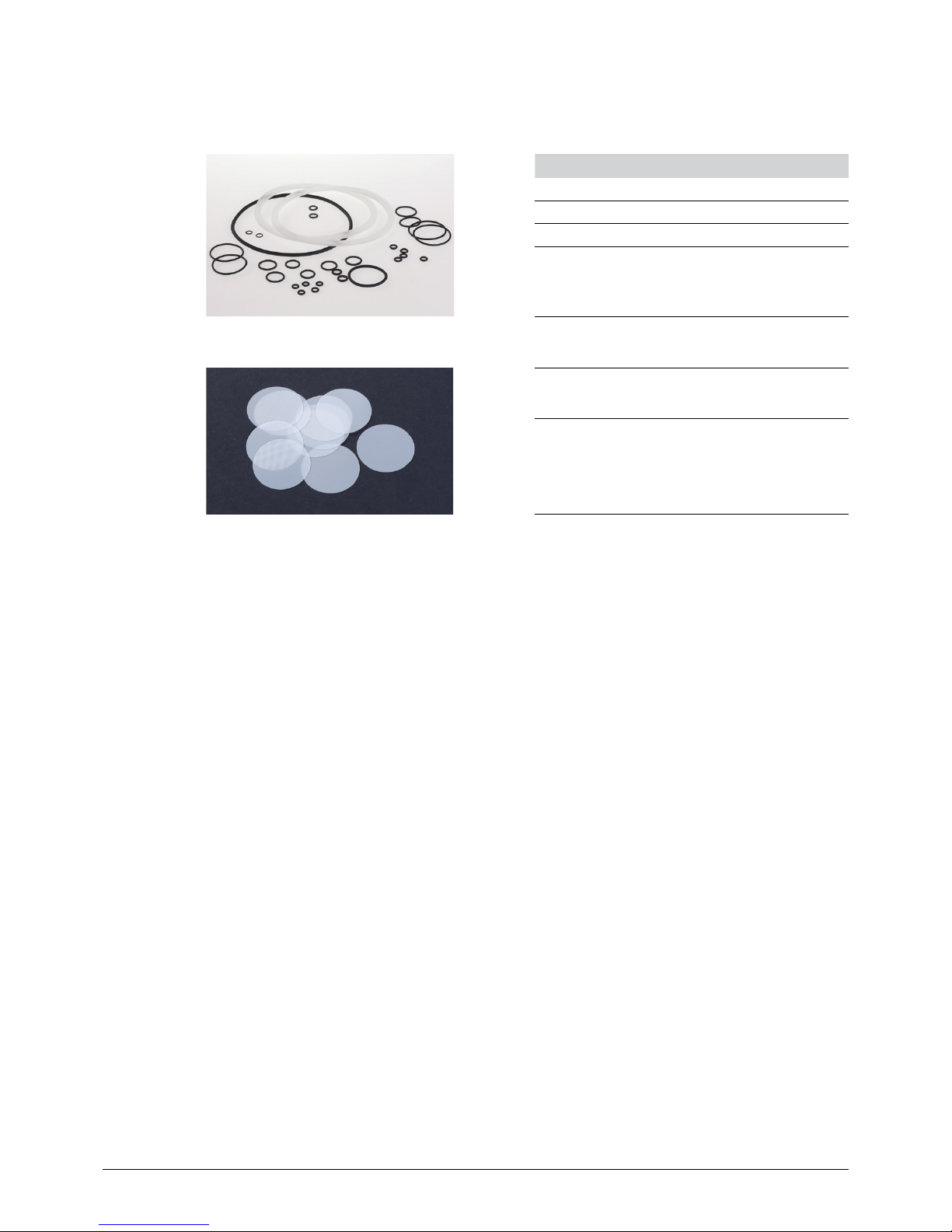
O-ring set for single nozzle 11057954
O-ring set for concentric nozzle 11057955
Pre-filters for nozzle,
diameter 7 mm (10 pcs.)
11057957
Drain filters for reaction vessel,
diameter 35 mm (10 pcs.)
11057958
Page 15

3 Technical data
15
B-390 Operation Manual, Version E
3.2 Technical data
Table 3-5: Technical data Encapsulator B-390
Power consumption max. 150 W
Connection voltage 100–240 VAC
Mains supply voltage fluctuations up to ±10% of the nominal voltage
Frequency 50/60 Hz
Fuse 3.15 A
Dimensions (W × H × D) 32×29×34 cm
Weight 7 kg
Nozzle diameter of single (= core) nozzles 0.08, 0.12, 0.15, 0.20, 0.30, 0.45, 0.75 and 1.00 mm
Nozzle diameter of shell nozzles 0.20, 0.30, 0.40, 0.50, 0.60, 0.70 and 0.90 mm
Droplet size range 0.15 to 2.00 mm
Vibration frequency 40 to 6,000 Hz
Electrode tension 250 to 2,500 V
Heating 30 to 70 °C
Pump rate by air pressure 0.5 to 200 mL/min
Maximal allowed air pressure in the system 1.5 bar
Reactor gross volume 4.5 liter
Reactor working volume 2 liter
Parts in contact with medium autoclavable
Sterile working conditions limited
Overvoltage category II
Pollution degree 2
Environmental conditions:
Temperature 5–40 °C for indoor use only
Altitude up to 2000 m
Max. relative humidity (curve parameter) Maximum relative humidity 80 % up to 31 °C, then
decreasing linearly to 50 % relative humidity at 40 °C
Table 3-6: Material and Approvals
Material in contact with sample stainless steel, silicone, glass, FEP, PTFE
Approvals CE, CSA
3.3 Materials used
Table 3-7: Materials used
Component Material description
Bead producing unit Stainless steel,
sealings: EPDM
Nozzles Stainless steel, sealings: EPDM
Pressure bottle Stainless steel, 3.3 boroscillate glass, FEP, PTFE
sealings: silicone, EPDM
Page 16

4 Description of function
16
B-390 Operation Manual, Version E
4 Description of function
This chapter explains the basic working principle of the Encapsulator B-390. It also shows how the
instrument is structured and provides a general functional description of its assembly.
4.1 Functional principle
The instrument provides the following key functions:
Reproducible bead size from one production to the next
– Adjustable parameters (nozzle size, liquid flow rate and vibration frequency) determine bead
size.
Reproducible bead formation
– In the range of 0.15 mm to 2.0 mm.
High bead size uniformity
– Due to the integrated Electrostatic Dispersion Unit (EDU); approximately 5 % relative standard
deviation of bead size using pure alginate.
Immediate process control
– Visual monitoring in the light of a stroboscope lamp.
High cell viability
– Bead formation technique is at low shear stress and under physiological conditions, thus
resulting in high cell survival.
Batch size
– T
he batch size is of 5 mL to 1’000 mL and the dead volume is approximately 2 mL.
Set of 8 single nozzles
– The 8 nozzle sizes of 0.08, 0.12, 0.15, 0.20, 0.30, 0.45, 0.75 and 1.0 mm cover the bead size
range of approximately 0.15 mm to 2.0 mm.
Delivery of the polymer mixture
– By air pressure with flow rates from 70 mL/h (0.08 mm nozzle) to 2’500 mL/h (1.0 mm nozzle).
High bead production
– Up to 6000 beads are produced per second depending on encapsulation conditions and
polymer mixture.
Page 17

4 Description of function
17
B-390 Operation Manual, Version E
Figure 4-1: Schematic representation of the Encapsulator B-390
a Pressure bottle
Bead producing unit
Vibration unit
Single nozzle
Electrode
Dispersion control
Vibration control
LED/stroboscope
Polymerization bath
Magnetic stirrer
(P) Air pressure
Page 18

4 Description of function
18
B-390 Operation Manual, Version E
The main parts of the Encapsulator B-390 are the control unit, the bead producing unit, and the pressure bottle. All parts of the instrument which are in direct contact with the immobilization mixture can
be sterilized by autoclaving.
The product to be encapsulated (active ingredients, enzymes, chemicals and cells) is mixed with an
encapsulating polymer (typically alginate) and the mixture put into the pressure bottle a see figure
4-1. The polymer-product mixture is forced into the bead producing unit by air pressure (P). The
liquid then passes through a precisely drilled nozzle and separates into equal size droplets on
exiting the nozzle. These droplets pass through an electrical field between the nozzle and the electrode resulting in a surface charge. Electrostatic repulsion forces disperse the beads as they drop
to the polymerization bath. The polymerization bath must be electrically grounded.
Bead size
The bead size is controlled by several parameters including the vibration frequency, nozzle size, flow
rate, and physical properties of the encapsulation mixture. In general, the bead size is twice the nozzle
diameter. But, by varying the jet velocity and the vibration frequency, the range can be adjusted by
about 1 - 15 %.
Optimal parameters for bead formation are indicated by visualization of real-time bead formation in the
light of a stroboscope lamp . When optimal parameters are reached, a standing chain of droplets is
clearly visible. Once established, the optimal parameters can be preset for subsequent bead production runs with the same encapsulating mixture.
Depending on several variables, up to 6000 beads are generated per second and collected in the
polymerization bath , which is continuously mixed by a magnetic stir bar. In addition, the reaction
solution must be electrically grounded to eliminate the electrostatic charges coming from the charged
bead surface. At the conclusion of the production run, the hardening solution is drained off, washing
solutions, or other reaction solutions, are added to further process the beads if needed.
4.2 Connections at the Encapsulator B-390
Front connections (See figure 5-2)
• Main switch
• Air out
• Electrode
• Ground
Rear connections (See figure 5-1)
• Electric supply
• Air inlet
• Vibration
• Optional plug(s)
Page 19

5 Putting into operation
19
B-390 Operation Manual, Version E
5 Putting into operation
This chapter describes how the instrument has to be installed. It also gives instructions for the initial
startup.
NOTE
Inspect the instrument for damages during unpacking. If necessary, prepare a status report immediately to inform the postal company, railway company or transportation company. Keep the original
packaging for future transportation.
5.1 Installation site
Put the instrument on a stable, horizontal surface. Consider the maximum product dimensions and
weight. The instrument must be set up in such a way that the main switch and the mains plug are
easily accessible at all times.
Obtain the environmental conditions as described in section 3.2 “Technical data”.
!
Warning
Death or serious injuries by use in explosive environments.
• Do not operate the instrument in explosive environments.
!
Warning
Death or serious poisoning by contact or incorporation of harmful substances.
• Wear safety goggles.
• Wear safety gloves.
• Wear a laboratory coat.
• Clean the instrument and all accessories thoroughly to remove possibly dangerous
substances.
• Do not clean dusty parts with compressed air.
• Store the instrument and its accessories at a dry place.
Page 20

5 Putting into operation
20
B-390 Operation Manual, Version E
5.2 Installing the Encapsulator B-390
Place the instrument on the lab bench with convenient access to an AC electrical outlet and to
compressed air. Place the instrument in a way that disconnection of the electric supply plug is
possible at all times.
Connect the external air/gas supply (=air inlet) and the vibration unit as shown in figure 5-1.
a Air inlet (blue tube 2.6×4.0 mm)
Electric supply socket with inte-
grated fuse
Socket for vibration unit
Optional socket
Figure 5-1: Rear view of the control unit
All controlling systems for bead production are incorporated in the control unit. Vibration frequency,
light intensity, electrostatic dispersion and heating, are controlled on the touch screen. Air pressure
is regulated with the pressure regulating valve. The pressure is electronically indicated on the touch
screen. The pumping rate of the polymer mixture is controlled with the liquid flow regulating valve.
The integrated stroboscope lamp allows real time jet breakup control. The main switch is on the front
panel. The bead producing unit is attached to the carrier plate with two screws (M3×25).
a Vibration unit
Touch screen
Pressure regulating valve
Mains switch
Plug for grounding wire
Air outlet
Liquid flow regulating valve
Liquid flow regulating valve
Heating block
Carrier plate
k Electrode
Stroboscope lamp
Figure 5-2: Front view of the control unit
Page 21

5 Putting into operation
21
B-390 Operation Manual, Version E
Installation of the air line
A 3 m air tube (2.6×4.0 mm) is included with each Encapsulator to connect it to external compressed
air or nitrogen.
1. Stick the air tube into the air inlet plug.
2. Attach the other side of the air tube to the external gas supply.
3. Deliver gas to the Encapsulator at 1.5 to 2 bar (23 to 30 psi) when running the instrument.
NOTE
The integrated pneumatic system (valve and fittings) will tolerate up to 7 bar (100 psi) at the inlet. An
over pressure safety valve, which opens at 1.5 bar, is incorporated after the pressure regulating valve, so
that the maximum air pressure at the air outlet is 1.5 bar. However the working range is from 0 to 1 bar.
5.3 Electrical connections
Verify that the electrical requirement of the unit, stated on the type plate of the control unit, corresponds to voltage of your local electrical network. Connect the power plug of the Encapsulator to the
mains supply.
!
Caution
Risk of instrument damage by wrong mains supply.
• External mains supply must meet the voltage given on the type plate.
• Check for sufficient grounding.
• Additional electrical safety measures such as residual current breakers may be necessary to
meet local laws and regulations! External connections and extension lines must be provided
with an earthed conductor lead (3-pole couplings, cord or plug equipment). All used power
cords shall be equipped with molded plugs only to avoid risks due to unobservant defective
wiring.
Page 22

5 Putting into operation
22
B-390 Operation Manual, Version E
5.4 Assembling of the bead producing unit
The bead producing unit is the central part of the Encapsulator B-390. It is fully autoclavable.
Figure 5-3 shows the different parts of the bead producing unit. The assembled bead producing unit
is attached with the screw on the carrier plate of the control unit. The vibration unit is placed on the
magnet holder without the need of further attachment.
a Magnet holder *
Membrane
Magnet
Flat gasket (14×1.78)
Pulsation chamber
Pre-filter with 50 µm mesh
O-ring (3.68x1.78)
Luer Lock
Screw M3×8
Screw M3×25
k Screw M3×6
*with attached fixation ring and
screws M3×5.
You can remove the fixation
ring for cleaning.
Figure 5-3: Parts of the bead producing unit
5.5 Single (inner) nozzles
A high quality nozzle is crucial for homogenous bead production. The holes of the Encapsulator
nozzles are precisely drilled using the newest technology. Every Encapsulator B-390 is delivered with
a set of 8 nozzles; nozzle aperture sizes are 80, 120, 150, 200, 300, 450, 750 µm and 1.0 mm. They
are made completely of stainless steel.
Figure 5-4: Set of 8 nozzles on the nozzle rack
The nozzle rack contains 8 nozzles (80, 120, 150, 200, 300, 450, 750 µm, and 1.0 mm). The size of
the O-ring is 4.47×1.78.
Page 23

5 Putting into operation
23
B-390 Operation Manual, Version E
5.6 Electrode
The electrode is part of the electrostatic dispersion unit. It is attached from below to the heating block.
The distance between the electrode and the nozzle tip can be changed as needed. This distance is
approximately 3 to 8 mm. It should be set so that the droplets are formed near the upper side of the
electrode.
When the beads pass through the electrode they pick up the electrostatic charge. This electrostatic
charge is transferred to the polymerization bath and accumulates if the vessel is not grounded. The
electrostatic field created by the accumulated charges can be so strong that small beads are repelled
over the bath and will no longer enter it. Therefore, the grounding hook attached to the grounding wire
is put into the polymerization bath so that the electrostatic charges will flow to ground, see figure 5-8.
a Electrode hole
Screws of the clip to change
the length of the clip
Figure 5-5: Electrode with two clips
Figure 5-6: Grounding set
Page 24

5 Putting into operation
24
B-390 Operation Manual, Version E
Figure 5-7: Position of the electrode below the carrier plate
Figure 5-8: Grounding the polymerization bath
Page 25

5 Putting into operation
25
B-390 Operation Manual, Version E
5.7 Pressure bottle
The pressure bottle is an autoclavable container used to push the encapsulation mixture by air pressure into the bead producing unit. Figure 5-9 shows the different parts of the pressure bottle. The
glass recipient has a guaranteed pressure resistance of 1.5 bar.
The liquid flow rate is controlled at two levels:
1. With the air pressure by the pressure regulation system, and
2. with the liquid flow regulating valve situated on top of the control unit. The reproducibility of the
liquid flow rate from one run to the other is usually ±5 %.
Figure 5-9: Pressure bottle with HEPA filter for sterile pumping of the immobilization mixture with air pressure
a Pressure stable flask of 500 mL or 1,000 mL
HEPA air filter
PTFE tube (4×6)
Silicone tube for liquid (4×7)
Silicone tube for air (5×8)
Luer lock male, 4.8 mm ID
Nipple for quick coupling
Two port cap
Cap with PTFE fitting for 6 mm tubes
The air passes through a silicone tube with an inner diameter of 5 mm (5×8 mm). The Hepa-filter
prevents contamination of the sterile immobilization mixture and should be replaced according to the
manufacturer’s instructions or if signs of reduced air passage are noticeable.
The liquid passes from the inside of the bottle through a PTFE tube (3×6 mm) to the silicone tube
outside of the bottle. This silicone tube is attached to the bead producing unit with the luer lock male .
Page 26

5 Putting into operation
26
B-390 Operation Manual, Version E
5.7.1 Installation of the pressure bottle
1. Assemble and – if needed - autoclave the
pressure bottle.
2. Fill the bottle with the immobilization mixture.
3. Attach the silicone tube of the pressure bottle
to the luer lock inlet of the bead producing
unit.
4. Pass the silicone tube in the liquid regulating
flow valve. Squeeze it so that no liquid can
pass.
5. Insert the nipple of the air tube into the quick
coupling of the air outlet at the control unit.
Figure 5-10: Installed pressure bottle
Page 27

5 Putting into operation
27
B-390 Operation Manual, Version E
5.8 Option: Concentric nozzle system
The concentric nozzle system (CN system) is an optional kit to the single nozzle unit. It is for the
production of capsules in a one-step procedure. The system consists of CN bead producing unit, a
set of 7 shell nozzles (0.20, 0.30, 0.40, 0.50, 0.60, 0.70 and 0.90 mm) and one pressure bottle of
1000 mL. The shell liquid is pumped by air pressure using the pressure bottle.
The main parts of the concentric nozzle unit are (refer to figure 5-12):
• the nozzle pair with shell a and core nozzle.
• CN bead producing unit with CN pulsation body and magnet
holder .
Figure 5-11: Capsule formation
a Shell nozzle
Core nozzle
CN pulsation body
Magnet holder
Luer connection, for
core liquid
Luer connection, for
shell liquid
Vibration unit
Carrier plate
Figure 5-12: Schematic description of the concentric nozzle system
Page 28

5 Putting into operation
28
B-390 Operation Manual, Version E
Figure 5-13: CN bead producing unit with set of 7 shell nozzles. The following nozzle apertures are standard:
0.20, 0.30, 0.4, 0.50, 0.60, 0.70 and 0.90 mm.
Figure 5-14: Single parts of the CN bead producing unit
a Screw M3×6
Luer-Lock
Pre-filter with 50 µm mesh
Flat gasket (18/14×1.5)
Screw M3×8
Screw M3×25
O-Ring (3.68×1.78)
CN pulsation chamber
O-Ring 12.42×1.78
CN magnet holder
k Membrane
Magnet
Page 29

5 Putting into operation
29
B-390 Operation Manual, Version E
5.8.1 Mounting of CN nozzles
Put the O-ring 12.42×1.78 in the grove of the CN
bead producing unit. Put the inner nozzle (with
attached O-ring) into the hole of the CN bead
producing unit. There is no thread. The inner
nozzle is centered and fixed by the shell nozzle.
a Exit of the shell liquid
O-ring 12.42×1.78
Figure 5-15: Mounting of the inner nozzle
Put carefully the shell nozzle over the inner
nozzle. Attach the shell nozzle with two screws
(M3×6). The shell nozzle centers and fixes the
inner nozzle.
Figure 5-16: Mounting of the shell nozzle
Figure 5-17: Installation of the concentric nozzle system
Page 30

5 Putting into operation
30
B-390 Operation Manual, Version E
Attach the complete CN bead producing unit to the carrier plate with two screws (M3×25). Attach the
silicone tube of the core liquid to the core inlet port and the silicone tube of the shell liquid to the shell
inlet port.
Pass the silicone tubes in the liquid regulating flow valves. Squeeze them so that no liquid can pass.
Figure 5-18: Connection of the pressure bottles to the air outlet. A T-piece feeds both pressure bottles.
5.9 Final installation check
This check has to be carried out after every installation and prior to the first encapsulation process. All
connected supply media (e.g. mains voltage and gas pressure) must match the technical data of the
installed system or system set-up.
• Inspect all glass components for damage.
• Check all other electrical connections for proper connection, such as optional or external components, e.g. magnetic stirrer, vibration unit, etc.
Page 31

6 Operation
31
B-390 Operation Manual, Version E
6 Operation
This chapter gives examples of typical instrument applications and instructions on how to operate the
instrument properly and safely. See also section 2.5 “Product safety” for general warnings.
6.1 Starting up the instrument
• Make sure the Encapsulator B-390 is properly connected to the mains supply.
• Carry out a final installation check (see section 5.9) before every bead production.
• Switch on the Encapsulator B-390. The system runs an internal check.
6.2 Screens and menu functions
All controlling systems for bead production are incorporated in the control unit. Vibration, frequency,
heating, light intensity of stroboscope lamp, and electrostatic dispersion (electrode) are controlled on
the touch screen. Air pressure is regulated with the pressure regulating valve. The pressure is indicated
on the touch screen.
The integrated stroboscope lamp allows real time jet breakup control.
When the Encapsulator is switched on the touch screen runs an initialization program for few seconds.
Then the screen shows the start menu with four sub-parts (see figure 6-1 to 6-5) for frequency, electrode, heating and more options concerning frequency. Further are on the screen the indication of the
pressure and the button “store” for saving the set values.
Screen 6-1: Start menu of the Encapsulator touch screen
a on/off switch for frequency control.
Indication of control parameter and status of control
(value or off).
Button for passing to screen 6-2 for setting frequency
parameters.
Button for storing set values: press twice within one
second. A sound indicates that the values are stored.
on/off switch for electrode control.
Button for passing to screen 6-3 for setting electrode
parameters.
Button for passing to screen 6-5 for setting more
frequency parameters.
on/off switch for heating control.
Button for passing to screen 6-4 for setting heating
parameters.
Indication of pressure.
NOTE
Icons with a thick bar at the bottom e.g.
on
off
activate/stop a process or lead to another screen.
Page 32

6 Operation
32
B-390 Operation Manual, Version E
The frequency regulation generates the appropriate electric oscillation in the vibration unit. Pressing on the (+) and
(–) buttons will change the frequency. Pressing the “on/off”
button activates or deactivates frequency. Pressing “Esc”
will return you to the start menu and the set value will be
kept.
Screen 6-2: Frequency regulation
The electrostatic dispersion unit is used to charge the
surface of the beads. The repulsion forces induced by the
equally charged surfaces prevent the beads from hitting
each other in flight, and from hitting each other as they enter
the hardening solution. The applied voltage often lies in the
range of 500 to 2000 V, depending primarily on the bead
size and the liquid flow velocity. In this way, the Encapsulator
B-390 can routinely generate bead batches with homogeneity greater than 95 %.
Pressing on the (+) and (–) buttons changes the electrostatic
dispersion parameter. The system needs few moments to
reach the set value. Pressing “Esc” will return you to the
start menu and the set value will be kept.
Screen 6-3: Electrostatic dispersion unit
Pressing on the (+) and (–) buttons will change the heating
parameter. The system will need several minutes to reach
the set value. Pressing the “on/off” button activates or
deactivates heating. Pressing “Esc” will return you to the
start menu and the set value will be kept.
Screen 6-4: Heating regulation
Note
The indicated temperature is the temperature near the heater. The temperature of the bead
producing unit and of the nozzle are some degrees lower.
When starting the heating; an internal program starts to compensate for this temperature difference
as much as possible. Therefore the real heating might be delayed for up to 2 minutes.
!
Caution
Hot surface while heating is switched on.
• Do not touch the heating block or the carrier plate while heating is switched on. The surface of
both elements becomes hot during heating!
• Allow both elements to cool down before touching them if heating has been switched on
before.
Page 33

6 Operation
33
B-390 Operation Manual, Version E
The light intensity of the stroboscope lamp and amplitude
( = intensity) of the vibration can be set from 1 to 9. Above
a frequency of 1500 Hz the amplitude can be set from 1
to 12. By increasing the amplitude the vibration becomes
stronger. Values above 3 are mainly for solutions with
viscosity > 100 mPa s. Pressing on the (+) and (-) buttons
will immediately change the parameters.
Pressing the “Esc”-button will cause a return to the start
menu and the set value will be kept.
Screen 6-5: More options concerning amplitude of vibration
and light Intensity of the stroboscope lamp.
6.3 Menu structure of the control unit
The figure below shows a schematic overview of all menus of the Encapsulator B-390, each with the
available functionality.
Heating [°C]
Heating On/Off
Set Temperature
Main menu
FrequencyOn/Off
ElectrodeOn/Off
Store function
Set Freq. | Set Elect. | Set Heat.
Electrode [V]
ElectrodeOn/Off
Set Electrode
Frequency[Hz]
FrequencyOn/Off
Set Frequency
more Frequency
Set Light Intensity
Set Amplitude
HeatingOn/Off
More
|
Figure 6-1: Menu structure of the control unit
Page 34

6 Operation
34
B-390 Operation Manual, Version E
6.4 Manual air pressure control
In the control unit the pressure is manually controlled by the pressure regulating valve, integrated in
the front panel of the control unit (see figure 6-2). Set the air pressure at a value which is 0.2 to 0.3 bar
higher than the maximal air pressure needed during the encapsulation procedure; but not higher than
1 bar. Turning the knob of the pressure regulating valve clockwise increases the pressure, counterclockwise decreases the pressure. The knob of the pressure regulating valve has two positions. If it
is pushed in, it is locked, if it is pulled out, it is unlocked. Turning the knob counter-clockwise reduces
the pressure via the self-venting system in the valve. The pressure is indicated on the touchscreen (see
screen 6-1).
Note
• The pressure of air or nitrogen entering the control unit on the rear panel of the Encapsulator
should be below 7 bar (100 psi). The prefered range is between 1.5 and 2 bar (20 to 30 psi).
• Be aware that the pressure regulation system reacts relatively slowly, because the displacement
of air in or out through the constriction valve is delayed.
• Do not leave the gas supply line on when the Encapsulator is not being used. The self-venting
system in the valve would drain the gas tank.
• The maximum pressure at the air outlet is 1.5 bar (20 psi). This value is controlled by an incorporated overpressure safety valve, which opens at 1.5 bar. However the working range is from 0 to
1 bar.
Figure 6-2: Air pressure regulating system for manual
air pressure control - turning the pressure regulating
valve clockwise increases the pressure.
Page 35

6 Operation
35
B-390 Operation Manual, Version E
6.5 Practicing with the Encapsulator, using water
Before working with encapsulation polymers, use water for practicing with the Encapsulator to
become familiar with the effects of the controls.
1. Assemble the bead producing unit, screw the 0.30 mm single nozzle to the bead producing unit
and attach all on the carrier plate with the screw (M3×25). Fix the electrode. Place the vibration
unit on the bead producing unit.
2. Fill the pressure bottle with 200 to 300 mL distilled water and screw on the assembled cap. Pass
the silicon tube (4×7 mm) between the blades of the flow regulating valve and attach the male luer
lock fitting of the silicon tube to the female luer lock fitting of the bead producing unit. Squeeze the
valve by turning the knob clock wise so that the silicon tube is closed.
3. Open the external pressurized air supply. The air inlet pressure is optimally at 1.5 to 2 bar (20 to 30
psi). However the system tolerates air inlet pressures of up to 7 bar (100 psi).
4. Set the air outlet pressure to 0.2 bar with the pressure regulating valve. Check the readout periodi-
cally to verify that the air pressure still corresponds to the set value. Activate the vibration control
system and set the frequency at 800 Hz.
5. Open the flow regulating valve by turning the knob counter-clock wise until the water flows
through the silicone tubing and the bead producing unit to the nozzle where it forms a continuous
liquid jet. Adjust the liquid flow and/or the frequency to obtain a good bead chain in the light of the
stroboscope lamp. The desired setting is when the beads within the bead chain are clearly separated for several centimeters, starting 3 to 5 mm below the nozzle. Record the position of the flow
regulating valve for this desired setting.
6. Increase the vibration frequency until the bead chain becomes unstable. Then increase the liquid
flow rate by slowly increasing the air pressure until a uniform bead chain is restored. Repeat this in
the opposite direction by decreasing the flow rate and compensating by decreasing the vibration
frequency. This may be done until you become familiar with the relationship between these two
settings. Record the values in table 6-1.
NOTE
• The liquid flow rate and the vibration frequency influence each other within a given working range.
The working range itself is mainly determined by the nozzle diameter and the viscosity of the polymer
mixture.
• An air pressure setting between 0.05 to 0.15 bar is sufficient to pump distilled water. Greater
working pressures indicate problems such as a clogged nozzle.
General Rules:
• Higher frequencies generate smaller bead sizes.
• Lower liquid flow rates generate smaller bead sizes.
Page 36

6 Operation
36
B-390 Operation Manual, Version E
Table 6-1: Determination of the working field (with pressure bottle)
Nozzle size:
Air pressure Clear bead chain without
electrostatic tension
Clear bead chain with
electrostatic tension
Lowest
frequency
Highest
frequency
Electrostatic
Voltage
Lowest
frequency
Highest
frequency
Nozzle size:
Air pressure Clear bead chain without
electrostatic tension
Clear bead chain with
electrostatic tension
Lowest
frequency
Highest
frequency
Electrostatic
Voltage
Lowest
frequency
Highest
frequency
Page 37

6 Operation
37
B-390 Operation Manual, Version E
7. Set the liquid flow rate and the vibration frequency to a value where a clear bead chain is obtained.
Activate the electrostatic dispersion unit at 300 V and increase the tension stepwise by 100 V until
the one-dimensional liquid jet is transformed into a funnel-like multi-line stream. The higher the
electrostatic charge the earlier the bead chain is separated. This prevents the beads from hitting
each other in flight, and from hitting each other as they enter the hardening solution. Therefore the
Encapsulator can routinely generate bead batches with homogeneity greater than 95 %. If nothing
happens, check that the electrode is connected to the control unit.
8. Change the vibration frequency and the flow rate and observe their influence on the electrostatic
tension needed to generate a jet separation. The use of electrostatic tension enlarges the working
range.
It can happen that after some time, the beads no longer enter, or actually jump out of the beaker.
This is due to the fact that electrostatic charges have accumulated in the electrically isolated
beaker. To avoid this phenomenon, place the supplied stainless steel clip of the grounding wire
over the edge of the beaker so it extends into the receiving liquid and connect the green-yellow
wire to the grounding plug on the front panel of the control unit. (See figure 6-3).
Figure 6-3: Grounding the open polymerization bath
General Rule:
The larger the beads, the higher the electrostatic voltage needed to seperate the jet.
9. Change the amplitude of the vibration. You will observe only slight changes of the bead chain.
Very often values between 1 and 3 are optimal for low viscous solutions. If using immobilization
mixtures with rather high viscosity (> 150 mPa s), values higher than 3 might be more appropriate.
10. Repeat this procedure with another nozzle size.
General Rule:
• Smaller nozzles generate smaller bead sizes.
• The final bead diameter will be approximately 2 times the nozzle size.
Page 38

6 Operation
38
B-390 Operation Manual, Version E
6.6 Practicing with the Encapsulator, using alginate solution
After getting comfortable with the bead formation controls, perform test runs with non-sterile alginate solutions. Sodium alginate is the most commonly used polymer, but there are others in use
with varying properties. We recommend the low viscosity grade alginate. The alginate concentration
strongly influences the viscosity and this in turn influences the pressure drop in the nozzle. Therefore, the maximum concentration of the alginate solution is a function of the nozzle diameter (see the
following table).
Table 6-2: Recommended alignate concentration (based on dry weight) for different nozzle diameters
Nozzle diameter Concentration of low viscosity grade alginate
Working range Recommended concentration
80 to 120 µm 0.75 to 1.4 % 1.1 to 1.2 %
120 to 200 µm 1.0 to 1.6 % 1.3 to 1.4 %
200 to 300 µm 1.2 to 1.8 % 1.5 to 1.6 %
300 to 500 µm 1.5 to 2.5 % 1.8 to 2.0 %
NOTE
Under normal storage conditions the alginate powder contains 10 - 12 % water. Therefore we refer to
the alginate concentration on a dry weight base.
6.6.1 Preparation of 1.5 % Na-alginate solution
1. Take a 400 mL beaker and weigh in 3.3 g Na-alginate powder of low viscosity grade.
2. Add 200 mL of deionized water and mix vigorously with a laboratory mixer for 1 to 2 minutes.
3. Alginate has the tendency to get lumpy. Remove the alginate lumps from the beaker and the mixer
blades with a spatula and mix again for 1 to 2 minutes. If lumps remain in the liquid, repeat mixing.
4. Then let the mixture stand so that the trapped air bubbles will escape from the liquid.
5. If needed, de-gas the mixture under reduced pressure.
6. Dissolution of alginate with a magnetic stirrer takes much more time and should be done over-
night.
NOTE
Alginate solutions will support the growth of microorganisms and are stable for about 2 weeks in a
refrigerator. An indication of microbial contamination is reduction of the mixture’s viscosity. Alginate
solutions can be stored for much longer time, even at room temperature, if sterilized or if preservatives are added, like 0.05 % NaN3.
Page 39

6 Operation
39
B-390 Operation Manual, Version E
6.6.2 Working with alginate solution
1. Attach a 200 µm or 300 µm nozzle to the assembled bead producing unit. Attach all to the carrier
plate. Check that the electrode is attached. Put the vibration unit on the bead producing unit. Put
a magnetic stirrer below the nozzle and a large beaker on the stirrer. Fill the beaker with 100 mM
CaCl2 so that at least 2 cm (approx. ¾”) is filled with the polymerization liquid. Put a magnetic stir
bar in the beaker and adjust the stirrer, so that a slight vortex is visible. Also, place the grounded
clip over the edge of the beaker and into the liquid. At this time, either cover the beaker with a
plate (petri dish) or move it and the stirrer out of the way and position an empty beaker (and the
grounding clip) under the nozzle in its place.
2. Fill the pressure bottle with the above described 1.5 % alginate solution and screw on the
assembled cap. Pass the silicon tube (4×7 mm) between the blades of the liquid flow regulating
valve and attach the male luer lock fitting of the silicon tube to the female luer lock fitting of the
bead producing unit. Squeeze the valve by turning the knob clock wise so that the silicon tube is
closed.
3. Open the external pressurized air supply. The air inlet pressure is optimally at 1.5 to 2 bar (20 to 30
psi). However the system tolerates air inlet pressures of up to 7 bar (100 psi).
4. Set the air pressure to 0.4 bar at the pressure regulation system. Check the readout periodically to
verify that the air pressure still corresponds to the set value. Activate the vibration control system
and set the vibration frequency at 1100 Hz for the 200 µm nozzle and at 800 Hz for the 300 µm
nozzle.
5. Open the liquid flow regulating valve by turning the knob counter-clock wise until the liquid flows
through the silicone tubing and the bead producing unit to the nozzle where it forms a continuous
liquid jet. Adjust the liquid flow and/or the frequency to obtain a good bead chain in the light of the
stroboscope lamp. The desired setting is when the beads within the bead chain are clearly separated for several centimeters, starting 3 to 5 mm below the nozzle. Record the position of the flow
regulating valve for this desired setting.
6. Increase the vibration frequency until the bead chain becomes unstable. Then increase the liquid
flow rate by slowly increasing the air pressure or by slowly opening the flow regulating valve until
a uniform bead chain is restored. Repeat this in the opposite direction by decreasing the flow rate
and compensating by decreasing the vibration frequency. This may be done until you become
familiar with the relationship between these two settings.
NOTE
An air pressure setting from 0.1 to 0.8 bar is generally sufficient to pump the polymer mixture.
Working pressures greater than 1.0 bar should be avoided and are indicative of problems such as:
• Clogged nozzle,
• Overly viscous polymer mixture,
• Under sized nozzle for the polymer mixture in use.
7. Activate the electrostatic dispersion unit at 500 V. Increase the voltage by steps of 100 V to get a
circular dispersal of the bead stream 3 to 10 cm (1” to 4”) after the electrode. An optimal distance
is about 5 cm (approx. 2”) below the electrode.
Page 40

6 Operation
40
B-390 Operation Manual, Version E
NOTE
The stronger the circular dispersal of the bead stream the better is the bead homogeneity. This does
not only depend on the electrostatic tension, but the liquid flow rate and the vibration frequency are
also factors. Ideally, the bead should separate from the liquid jet within the electrostatic field between
the nozzle and the end of the electrode.
8. As soon as a symmetrical and stable dispersal is obtained, remove the plate from the beaker
filled with polymerization solution or replace the beaker of water with the beaker of polymerization
solution and the stir plate (and the grounding forceps), and collect the beads for about 1 minute.
Record the process parameters in table 6-3 while the beads are accumulating. Cover or switch
the beaker and stop the bead production by turning off the electrostatic voltage and vibration
control.
NOTE
Clean the nozzle thoroughly immediately after each run with distilled water to avoid nozzle clogging or
partial occlusion due to dried out polymer mixture.
9. Check the beads under a microscope with a micrometer scale eyepiece, and record your obser-
vations of diameter, uniformity and shape in table 6-3.
10. Repeat this process for each change in process parameters.
Table 6-3: Encapsulator trial test work sheet (pressure bottle)
Nozzle size [µm]
Alginate concentr. [%]
Position of the flow regulating valve
Vibration frequency [Hz]
Amplitude
Approximate bead size [µm]
Homogeineity [%]
Comments
NOTE
When producing small beads with a diameter <500 µm, it may occur that their shape is not spherical
but somewhat oval. This is mainly due to the surface tension of the polymerization solution. A very
critical point for the bead is it‘s entrance into the polymerization solution. If the surface tension is
high, then the bead is partially held back at the surface and polymerization starts before the bead can
regain a round shape. This problem can be eliminated by adding a small quantity of surfactant like
Tween 20 to the polymerization mixture.
11. Compare the influence of the electrostatic tension by collecting beads at the same vibration
frequency and pumping rate with and without the electrostatic tension function turned on.
Page 41

6 Operation
41
B-390 Operation Manual, Version E
6.7 Theoretical background
Equ. 1:
When a laminar jet is mechanically disturbed at the frequency ƒ,
beads of uniform size are formed1. The optimal wavelength λ
opt
for
breakup, according to Weber2 is given by:
Equ. 2:
where: D = nozzle diameter
η = dynamic viscosity [Pa s]
ρ = density [kg/m3]
(ca. 1000 kg/m3 for alginate solutions)
σ = surface tension [N/m]
(ca. 55×10-3 N/m for alginate solutions)
λ
opt
is the optimal wavelength to get the best bead formation for the given nozzle diameter and the
viscosity of the encapsulation mixture. It is possible to change λ
opt
by 30 % and still achieve a good
bead formation.
The diameter of a bead = d [m] can be calculated with the flow rate = V’ [m3/s] and the frequency of
the pulsation ƒaccording to:
Equ. 3:
The jet velocity = v [m/s] and the nozzle diameter = D [m] are correlated to the flow rate (V’) according
to:
Equ. 4:
Figure 6-4 shows the dependence of the flow rate to the jet velocity and the nozzle diameter as calculated by Equation 4. Because the liquid must flow laminarly the working range of the jet velocity will
normally lay between 1.5 and 2.5 m/s, depending on the liquid viscosity and the nozzle diameter.
1
Lord Rayleigh 1878. Proc. London Math. Soc. 10:4.
2
Weber C. 1936. Zeitschrift für angewandte Mathematik und Mechanik. 11:136.
Page 42

6 Operation
42
B-390 Operation Manual, Version E
Figure 6-4: Influence of the liquid jet velocity and the nozzle diameter on flow rate, as calculated by Equation 4.
Figure 6-5 shows the correlation between the vibration frequency and the bead diameter for five
different flow rates as calculated by equation 4. Lower flow rates, which corresponds to lower
pumping rates, produce smaller beads. Higher vibration frequencies produce smaller beads also.
Figure 6-5: Influence of the vibration frequency and the flow rate on the bead diameter as calculated by Equation 4.
Page 43

6 Operation
43
B-390 Operation Manual, Version E
Table 6-4: Optimal working conditions for the Encapsulator determined with alginate solution
Nozzle diameter [µm] Flow rate * [mL/min] Frequency interval ** Amplitude Air pressure [bar]
1.0 mm 30 to 40 40 to 220 Hz 2 to 6 0.3 to 0.6
750 µm 19 to 25 40 to 300 Hz 2 to 5 0.3 to 0.5
450 µm 9 to 14 150 to 450 Hz 2 to 5 0.3 to 0.5
300 µm 5.5 to 7 400 to 800 Hz 1 to 3 0.3 to 0.5
200 µm 3.5 to 4.5 600 to 1200 Hz 1 to 3 0.4 to 0.6
150 µm 2.3 to 2.8 800 to 1800 Hz 1 to 3 0.4 to 0.6
120 µm 1.5 to 1.8 1000 to 2500 Hz 1 to 4 0.5 to 0.7
80 µm 1.1 to 1.3 1300 to 3000 Hz 1 to 4 0.5 to 0.7
* Tested with 2 % low viscosity grade alginate solution for 750 µm and 1.0 mm nozzle, with 1.5 %
alginate solution for the 150 to 500 µm nozzle and with 1.2 % alginate solution for the 80 and 120 µm
nozzles.
**Upper values with application of high voltage.
NOTE
For solutions with a viscosity different from the tested one, it can be said that:
• the higher the viscosity the higher the minimal jet velocity
• the higher the viscosity the higher the working flow rate
• the higher the viscosity the lower the optimal frequency
• the higher the viscosity the larger the beads
6.7.1 Bead productivity and cell density
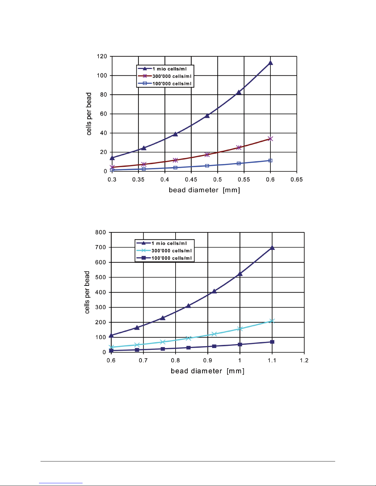
Figures 6-6 and 6-7 indicate the amount of beads formed from 1 mL of liquid. About 30,000 beads
with a diameter of 0.4 mm will be formed, but only 2,000 with a diameter of 1 mm.
Figures 6-8 and 6-9 indicate the number of cells which are encapsulated in one bead for a given
cell density and bead diameter. These figures may help you select the appropriate cell density in the
immobilization mixture. For example, if the immobilization mixture contains 1×10⁶ cells per mL, then
about 33 cells are, on average, in each 0.4 mm bead, but, about 520 cells will be in each 1 mm bead.
Page 44

6 Operation
44
B-390 Operation Manual, Version E
Figure 6-6: Amount of beads with a diameter of 0.3 to 0.6 mm formed from 1 mL of immobilization mixture.
Figure 6-7: Amount of beads with a diameter of 0.6 to 1.1 mm formed from 1 mL of immobilization mixture.
Page 45
6 Operation
45
B-390 Operation Manual, Version E
Figure 6-8: Amount of cells per bead made from different cell concentrations for bead diameters of 0.3 to 0.6 mm.
Figure 6-9: Amount of cells per bead made from different cell concentrations for bead diameters of 0.6 to 1.1 mm.
Page 46

7 Maintenance and repairs
46
B-390 Operation Manual, Version E
7 Maintenance and repairs
This chapter gives instructions on maintenance work to be performed in order to keep the instrument
in good and safe working condition. All maintenance and repair work requiring the opening or removal
of the instrument housing must be carried out by trained personnel and only with the tools provided
for this purpose.
Note
Use only genuine consumables and spare parts for any maintenance and repair work in order to
assure warranty and continued system performance. Any modifications of the Encapsulator B-390 or
parts of it need prior written permission of the manufacturer.
7.1 Customer service
Only authorized service personnel are allowed to perform repair work on the instrument. Authorization requires a comprehensive technical training and knowledge of possible dangers which might arise
when working at the instrument. Such training and knowledge can only be provided by BUCHI.
Addresses of official BUCHI customer service offices are given on the BUCHI website under:
www.buchi.com. If malfunctions occur on your instrument or you have technical questions or application problems, contact one of these offices.
The customer service offers the following:
• Spare part delivery
• Repairs
• Technical advice
7.2 Housing condition
Check the housing for visible defects (switches, plugs, cracks) and clean it regularly with a damp cloth.
The Encapsulator control unit should be handled as with any other piece of electrical equipment. The
front panel is covered by a polyamide sheet, so that it may be cleaned with a mild detergent solution
or alcohol.
7.3 Sealing conditions
It is recommended to check the integrity of the sealings on a regular base. Gaskets, O-rings and silicone tubing should be replaced periodically (approximately once per year). Check all parts before use
and replace if needed.
Page 47

7 Maintenance and repairs
47
B-390 Operation Manual, Version E
7.4 Cleaning
!
Warning
Pressure increase in the inlet-system due to clogged nozzles.
Bursting of the inlet system.
Death or serious poisoning by contact or incorporation of harmful substances at use.
• Clean nozzle immediately after use, see following section.
Wear laboratory coat
Wear protective goggles
Wear protective gloves
7.4.1 Cleaning the nozzle after each immobilization run
It is critical to clean the nozzle immediately after use so that the encapsulation medium (alginate, etc.)
will not dry and clog the system.
1. Leave the nozzle in place on the bead producing unit.
2. Attach a 20 mL or 60 mL syringe to the bead producing unit and inject 20 to 60 mL of distilled
water or of the solvent used for the encapsulation polymer.
3. If needed unscrew the nozzle from the bead producing unit, rinse with deionized water (see
figure 7-1) or an appropriate solvent and dry the nozzle with a flush of air.
Page 48

7 Maintenance and repairs
48
B-390 Operation Manual, Version E
Figure 7-1: Cleaning procedure of the nozzle
– Take a syringe containing air on top and water on the bottom.
– Push the air through the nozzle (left figure).
– Push the water through the nozzle immediately afterwards (right figure).
– Examine the nozzle tip under a stereoscopic microscope to make sure the passage is
clear and clean.
NOTE
If lipophilic immobilization solutions were used, then use appropriate solvents for cleaning. Do not use
acid solution for alginate, as this would create a precipitate.
7.4.2 Cleaning a clogged nozzle
Unscrew the nozzle. Pass air or water through the nozzle as shown in figure 7-1.
If the nozzle tip is not clear, soak the nozzle in water, the appropriate solvent, in 1N NaOH or 1N
sulfuric acid (never use HCl) according to the encapsulation mixture for 1 hour at room temperature,
with periodic agitation. Sonication of full stainless steel nozzles is also a helpful procedure. Wear
appropriate protection equipment. Rinse with distilled water, with air and let dry.
Examine the nozzle tip under a stereoscopic microscope to make sure the passage is clear and clean.
NOTE
If lipophilic immobilization solutions were used, then use appropriate solvents for cleaning. Do not use
acid solution for alginate, as this would create a precipitate.
7.4.3 Cleaning the bead producing unit
Disassemble the bead producing unit. However the magnet holder should not be disassembled!
Wash all parts, with a mild detergent solution, 0.01N NaOH or 0.01N sulfuric acid (never use HCl) as
appropriate.
Rinse thoroughly with hot water, then with distilled water and let dry.
Page 49

8 Troubleshooting
49
B-390 Operation Manual, Version E
8 Troubleshooting
8.1 Malfunctions and their remedy
The table below lists possible operating errors and their cause. As remedy set the parameter stepwise
in the opposite direction or fix the missing part.
Table 8-1: Possible cause
Problem Possible cause
Unstable liquid stream The liquid flow rate is too low.
The nozzle is not adequately cleaned (frequent cause).
The frequency is too high.
The amplitude is too high.
Unstable bead chain The frequency is too high or too low.
The liquid flow rate is too high or too low.
The Nozzle is not adequately cleaned.
The amplitude is too low or too high.
Non-homogenous bead-size-distribution The liquid flow rate is too high.
The frequency is too high.
The electrostatic tension is too low.
The immobilization mixture is a non-Newtonian liquid, making it
difficult to extrude or to prill.
The bead chain does not separate The electrode is not connected to the control unit.
The electrical tension is too low.
The electrode is not on.
Beads are not visible in the strobo light The vibration unit is not activated.
The vibration unit is not put on the bead producing unit.
The vibration frequency is too low or too high.
The viscosity of the immobilization mixture is too high.
Page 50

9 Shutdown, storage, transport and disposal
50
B-390 Operation Manual, Version E
9 Shutdown, storage, transport and disposal
This chapter instructs how to shut down and to pack the instrument for storage or transport. Specifications for storage and shipping conditions can also be found listed here.
9.1 Storage and transport
Switch off the instrument and remove the power cord. Wait until all hot parts (e.g. heating block and
carrier plate) have cooled down.
To disassemble the Encapsulator B-390 follow the installation instructions in section 5 in reverse
order. Remove all liquids and dusty residues before packaging the instrument.
!
Warning
Death or serious poisoning by contact or incorporation of harmful substances.
• Wear safety goggles
• Wear safety gloves
• Wear a laboratory coat
• Clean the instrument and all accessories thoroughly to remove possibly dangerous substances
• Do not clean dusty parts with compressed air
• Store the instrument and its accessories at a dry place in its original packaging
Page 51

9 Shutdown, storage, transport and disposal
51
B-390 Operation Manual, Version E
9.2 Disposal
For instrument disposal in an environmentally friendly manner, a list of materials is given in chapter 3.3.
This helps to ensure that the components can be separated and recycled correctly.
You have to follow valid regional and local laws concerning disposal. For help, please contact your
local authorities!
NOTE
When returning the instrument to the manufacturer for repair work, please copy and complete the
health and safety clearance form in section 10.2 and enclose it with the instrument.
Page 52

10 Declarations and requirements
52
B-390 Operation Manual, Version E
10 Declarations and requirements
10.1 FCC requirements (for USA and Canada)
English:
This equipment has been tested and found to comply with the limits for a Class A digital device,
pursuant to both Part 15 of the FCC Rules and the radio interference regulations of the Canadian
Department of Communications. These limits are designed to provide reasonable protection against
harmful interference when the equipment is operated in a commercial environment.
This equipment generates, uses and can radiate radio frequency energy and, if not installed and used
in accordance with the instruction manual, may cause harmful interference to radio communications.
Operation of this equipment in a residential area is likely to cause harmful interference in which case
the user will be required to correct the interference at his own expense.
Français:
Cet appareil a été testé et s’est avéré conforme aux limites prévues pour les appareils numériques
de classe A et à la partie 15 des réglementations FCC ainsi qu’à la réglementation des interférences
radio du Canadian Department of Communications. Ces limites sont destinées à fournir une protection adéquate contre les interférences néfastes lorsque l’appareil est utilisé dans un environnement
commercial.
Cet appareil génère, utilise et peut irradier une énergie à fréquence radioélectrique, il est en outre
susceptible d’engendrer des interférences avec les communications radio, s’il n’est pas installé et
utilisé conformément aux instructions du mode d’emploi. L’utilisation de cet appareil dans les zones
résidentielles peut causer des interférences néfastes, auquel cas l’exploitant sera amené à prendre les
dispositions utiles pour palier aux interférences à ses propres frais.
Page 53

10 Declarations and requirements
53
B-390 Operation Manual, Version E
10.2 Health and Safety Clearance form
Health and Safety Clearance
Declaration concerning safety, potential hazards and safe disposal of waste.
For the safety and health of our staff, laws and regulations regarding the handling of
dangerous goods, occupational health and safety regulations, safety at work laws and
regulations regarding safe disposal of waste, e.g. chemical waste, chemical residue or
solvent, require that this form must be duly completed and signed when equipment or
defective parts were delivered to our premises.
Instruments or parts will not be accepted if this declaration is not present.
Equipment
Model: Part/Instrument no.:
1.A Declaration for non dangerous goods
We assure that the returned equipment
has not been used in the laboratory and is new
was not in contact with toxic, corrosive, biologically active, explosive, radioactive or
other dangerous matters.
is free of contamination. The solvents or residues of pumped media have been
drained.
1.B Declaration for dangerous goods
List of dangerous substances in contact with the equipment:
Chemical, substance Danger classification
We assure for the returned equipment that
all substances, toxic, corrosive, biologically active, explosive, radioactive or
dangerous in any way which have pumped or been in contact with the equipment
are listed above.
the equipment has been cleaned, decontaminated, sterilized inside and outside and
all inlet and outlet ports of the equipment have been sealed.
2. Final Declaration
We hereby declare that
- we know all about the substances which have been in contact with the equipment
and all questions have been answered correctly
- we have taken all measures to prevent any potential risks with the delivered
equipment.
Company name or stamp:
Place, date:
Name (print), job title (print):
Signature:
Page 54

Page 55

Page 56

Quality in your hands
BUCHI Affiliates:
We are represented by more than 100 distribution partners worldwide.
Find your local representative at: www.buchi.com
BUCHI Support Centers:
Europe
Switzerland/Austria
BÜCHI Labortechnik AG
CH – 9230 Flawil
T +41 71 394 63 63
F +41 71 394 65 65
buchi@buchi.com
www.buchi.com
Benelux
BÜCHI Labortechnik GmbH
Branch Offi ce Benelux
NL – 3342 GT Hendrik-Ido-Ambacht
T +31 78 684 94 29
F +31 78 684 94 30
benelux@buchi.com
www.buchi.be
France
BUCHI Sarl
FR – 94656 Rungis Cedex
T +33 1 56 70 62 50
F +33 1 46 86 00 31
france@buchi.com
www.buchi.fr
Germany
BÜCHI Labortechnik GmbH
DE – 45127 Essen
T +800 414 0 414 0 (Toll Free)
T +49 201 747 49 0
F +49 201 747 49 20
deutschland@buchi.com
www.buechigmbh.de
Italy
BUCHI Italia s.r.l.
IT – 20010 Cornaredo (MI)
T +39 02 824 50 11
F +39 02 575 12 855
italia@buchi.com
www.buchi.it
Russia
BUCHI Russia/CIS
Russia 127287 Moscow
T +7 495 36 36 495
F +7 495 98 10 520
russia@buchi.com
www.buchi.ru
United Kingdom
BUCHI UK Ltd.
GB – Oldham OL9 9QL
T +44 161 633 1000
F +44 161 633 1007
uk@buchi.com
www.buchi.co.uk
Germany
BÜCHI NIR-Online
DE – 69190 Walldor f
T +49 6227 73 26 60
F +49 6227 73 26 70
nir-online@buchi.com
www.nir-online.de
China
BUCHI China
CN – 200052 Shanghai
T +86 21 6280 3366
F +86 21 5230 8821
china@buchi.com
www.buchi.com.cn
India
BUCHI India Private Ltd.
IN – Mumbai 400 055
T +91 22 667 75400
F +91 22 667 18986
india@buchi.com
www.buchi.in
Indonesia
PT. BUCHI Indonesia
ID – Tangerang 15321
T +62 21 537 62 16
F +62 21 537 62 17
indonesia@buchi.com
www.buchi.co.id
Japan
Nihon BUCHI K.K.
JP – Tokyo 110-0008
T +81 3 3821 4777
F +81 3 3821 4555
nihon@buchi.com
www.nihon-buchi.jp
Korea
BUCHI Korea Inc.
KR – Seoul 153-782
T +82 2 6718 7500
F +82 2 6718 7599
korea@buchi.com
www.buchi.kr
Malaysia
BUCHI Malaysia Sdn. Bhd.
MY – 47301 Petaling Jaya,
Selangor
T +60 3 7832 0310
F +60 3 7832 0309
malaysia@buchi.com
www.buchi.com
Singapore
BUCHI Singapore Pte. Ltd.
SG – Singapore 609919
T +65 6565 1175
F +65 6566 7047
singapore@buchi.com
www.buchi.com
Thailand
BUCHI (Thailand) Ltd.
TH – Bangkok 10600
T +66 2 862 08 51
F +66 2 862 08 54
thailand@buchi.com
www.buchi.co.th
Asia
America
Brazil
BUCHI Brasil Ltda.
BR – Valinhos SP 13271-200
T +55 19 3849 1201
F +55 19 3849 2907
brasil@buchi.com
www.buchi.com
USA/Canada
BUCHI Corporation
US – New Castle, DE 19720
T +1 877 692 8244 (Toll Free)
T +1 302 652 3000
F +1 302 652 8777
us-sales@buchi.com
www.mybuchi.com
South East Asia
BUCHI (Thailand) Ltd.
TH-Bangkok 10600
T +66 2 862 08 51
F +66 2 862 08 54
bacc@buchi.com
www.buchi.com
Middle East
BÜCHI Labortechnik AG
UAE – Dubai
T +971 4 313 2860
F +971 4 313 2861
middleeast@buchi.com
www.buchi.com
Latin America
BUCHI Latinoamérica Ltda.
BR – Valinhos SP 13271-200
T +55 19 3849 1201
F +55 19 3849 2907
latinoamerica@buchi.com
www.buchi.com
 Loading...