

Page 1
Operation Manual
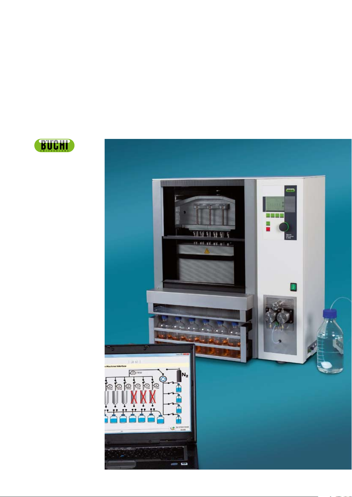
SpeedExtractor
Record 1.0
093266
en
Page 2

Page 3

Table of contents
Table of contents
1 About this manual and general information . . . . . . . . . . . . . . . . . . . . . . . . . 5
1.1 About this manual . . . . . . . . . . . . . . . . . . . . . . . . . . . . . . . . . . . . 5
1.2 Reference documents. . . . . . . . . . . . . . . . . . . . . . . . . . . . . . . . . . 5
1.3 Trademarks . . . . . . . . . . . . . . . . . . . . . . . . . . . . . . . . . . . . . . . 5
1.4 Abbreviations . . . . . . . . . . . . . . . . . . . . . . . . . . . . . . . . . . . . . . 5
2 Safety. . . . . . . . . . . . . . . . . . . . . . . . . . . . . . . . . . . . . . . . . . . . . . 6
2.1 Warning notices and messages used in this manual. . . . . . . . . . . . . . . . . . . 6
2.2 Software-related hazards . . . . . . . . . . . . . . . . . . . . . . . . . . . . . . . . 6
3 Technical data . . . . . . . . . . . . . . . . . . . . . . . . . . . . . . . . . . . . . . . . . 7
3.1 Minimum system requirements . . . . . . . . . . . . . . . . . . . . . . . . . . . . . 7
3.2 Program limitations . . . . . . . . . . . . . . . . . . . . . . . . . . . . . . . . . . . 7
3.3 Product feature list . . . . . . . . . . . . . . . . . . . . . . . . . . . . . . . . . . . 7
4 Description of function . . . . . . . . . . . . . . . . . . . . . . . . . . . . . . . . . . . . 8
4.1 Program window . . . . . . . . . . . . . . . . . . . . . . . . . . . . . . . . . . . . 8
4.2 Program structure overview . . . . . . . . . . . . . . . . . . . . . . . . . . . . . . . 9
4.3 Method handling . . . . . . . . . . . . . . . . . . . . . . . . . . . . . . . . . . . 10
4.4 Status . . . . . . . . . . . . . . . . . . . . . . . . . . . . . . . . . . . . . . . . . 10
4.5 Reporting . . . . . . . . . . . . . . . . . . . . . . . . . . . . . . . . . . . . . . . 10
4.5.1 Visualization . . . . . . . . . . . . . . . . . . . . . . . . . . . . . . . . . . . . . . 10
4.5.2 Report handling . . . . . . . . . . . . . . . . . . . . . . . . . . . . . . . . . . . . 10
4.6 Configuration . . . . . . . . . . . . . . . . . . . . . . . . . . . . . . . . . . . . . 10
5 Putting into operation . . . . . . . . . . . . . . . . . . . . . . . . . . . . . . . . . . . . 11
5.1 Step 1: Installing the program . . . . . . . . . . . . . . . . . . . . . . . . . . . . . 11
5.2 Step 2: Connecting a SpeedExtractor . . . . . . . . . . . . . . . . . . . . . . . . . 11
5.3 Step 3: Starting the program . . . . . . . . . . . . . . . . . . . . . . . . . . . . . 11
6 Operation . . . . . . . . . . . . . . . . . . . . . . . . . . . . . . . . . . . . . . . . . . 12
6.1 Initial program view . . . . . . . . . . . . . . . . . . . . . . . . . . . . . . . . . . 12
6.2 Method Handling . . . . . . . . . . . . . . . . . . . . . . . . . . . . . . . . . . . 13
6.2.1 Method handling view in detail: . . . . . . . . . . . . . . . . . . . . . . . . . . . . 14
6.3 Status . . . . . . . . . . . . . . . . . . . . . . . . . . . . . . . . . . . . . . . . . 16
6.4 Reporting . . . . . . . . . . . . . . . . . . . . . . . . . . . . . . . . . . . . . . . 17
6.4.1 Visualization . . . . . . . . . . . . . . . . . . . . . . . . . . . . . . . . . . . . . . 18
6.4.2 Report handling . . . . . . . . . . . . . . . . . . . . . . . . . . . . . . . . . . . . 19
6.4.3 Extraction report . . . . . . . . . . . . . . . . . . . . . . . . . . . . . . . . . . . 22
6.5 Configuration . . . . . . . . . . . . . . . . . . . . . . . . . . . . . . . . . . . . . 26
7 Workflow . . . . . . . . . . . . . . . . . . . . . . . . . . . . . . . . . . . . . . . . . . . 27
7.1 Software startup conditions . . . . . . . . . . . . . . . . . . . . . . . . . . . . . . 27
7.2 While recording . . . . . . . . . . . . . . . . . . . . . . . . . . . . . . . . . . . . 28
7.3 After recording . . . . . . . . . . . . . . . . . . . . . . . . . . . . . . . . . . . . 28
7.4 Creating a report . . . . . . . . . . . . . . . . . . . . . . . . . . . . . . . . . . . 28
7.5 Further report processing . . . . . . . . . . . . . . . . . . . . . . . . . . . . . . . 30
7.6 Method handling . . . . . . . . . . . . . . . . . . . . . . . . . . . . . . . . . . . 30
7.7 Method backup . . . . . . . . . . . . . . . . . . . . . . . . . . . . . . . . . . . . 31
8 Troubleshooting . . . . . . . . . . . . . . . . . . . . . . . . . . . . . . . . . . . . . . . 32
8.1 FAQ . . . . . . . . . . . . . . . . . . . . . . . . . . . . . . . . . . . . . . . . . . 32
3 SpeedExtractor Record 1.0 Operation Manual, Version A
Page 4

Table of contents
Read this manual carefully before installing and running the software and note the safety precautions
in section 2 in particular. Store the manual in the immediate vicinity of the instrument, so that it can be
consulted at any time.
No technical modifications may be made to the software without the prior written agreement of Buchi.
Unauthorized modifications may affect the system safety or result in accidents.
This manual is copyright. Information from it may not be reproduced, distributed, or used for competitive purposes, nor made available to third parties. The manufacture of any component with the aid of
this manual without prior written agreement is also prohibited.
If you need another language version of this manual, you can download available versions at
www.buchi.com.
4
SpeedExtractor Record 1.0 Operation Manual, Version A
Page 5

1 About this manual and general information
1.1 About this manual
This manual is part of the product. It describes the SpeedExtractor Record 1.0 software and provides
all information required for its use.
It is addressed to laboratory personnel and operators in particular.
Read the operating instructions before use.•
Observe all the safety instructions.•
Keep the operating instructions during the product lifetime.•
Pass the operating instructions to every subsequent owner or user of the product.•
1 About this manual
1.2 Reference documents
For information about the SpeedExtractor E-914/916, please refer to the corresponding manual.
Table of available language versions with their respective ordering numbers:
Language Ordering number
English 93218
German 93219
French 93220
Italian 93221
Spanish 93222
1.3 Trademarks
Trademarks
The following product names and any registered and unregistered trademarks mentioned in this
manual are used for identification purposes only and remain the exclusive property of their respective
owners:
SpeedExtractor™ is a trademark of Büchi Labortechnik AG•
Windows®•
1.4 Abbreviations
PC: Personal Computer
CD: Compact Disk
.csv: Comma-Separated Values (standard data-exchange format)
.xml: Extensible Markup Language
FAQ: Frequently Asked Questions
5 SpeedExtractor Record 1.0 Operation Manual, Version A
Page 6

2 Safety
This section highlights the safety concept of the SpeedExtractor Record Software 1.0 and contains
general rules of behavior and warnings from hazards concerning the use of the product.
The safety of users and personnel can only be ensured if these safety instructions and the safety
related warnings in the individual sections are strictly observed and followed. Therefore, the manual
must always be available to all persons performing the tasks described herein.
For further safety information and instruction about the SpeedExtractor, see section 1.2, Reference
documents for related documentation.
2.1 Warning notices and messages used in this manual
2 Safety
ATTENTION
With the general „read this“ symbol, ATTENTION indicates the possibility of software damage,
malfunctions or incorrect process results, if instructions are not followed.
NOTE
Useful tips for optimal use of the software.
2.2 Software-related hazards
ATTENTION
When the SpeedExtractor Record software is installed, the computer standby mode must be
deactivated within the power options to avoid loss of data during the use of the program!
6 SpeedExtractor Record 1.0 Operation Manual, Version A
Page 7

3 Technical data
3.1 Minimum system requirements
Operating System Requirements
Windows® XP Professional (32-bit only) 500 MHz CPU or faster
Windows® Vista™ Business (32-bit only) 1 GHz CPU or faster
3 Technical data
>100 MB of free harddrive space; 256 MB RAM
CD-ROM drive
>100 MB of free harddrive space; 1 GB RAM
CD-ROM drive
3.2 Program limitations
The SpeedExtractor Software 1.0 is a recording, method handling and report generating program only.
Thus, performing remote actions at the SpeedExtractor itself are not possible.
Due to software limitations, the program can only be used in configuration of a single SpeedExtractor
connected to a PC.
Linking one PC and to several SpeedExtractors will not be possible.•
Do not connect another SpeedExtractor to the PC, while the application is still running.•
3.3 Product feature list
The SpeedExtractor Record software provides the following features:
Managing and storage of methods•
Status view to visualize system and extraction status •
Graphical visualization of parameter chart and process reporting•
7 SpeedExtractor Record 1.0 Operation Manual, Version A
Page 8
4 Description of function
This section will introduce all basic functions provided by the software and its structure.
4.1 Program window
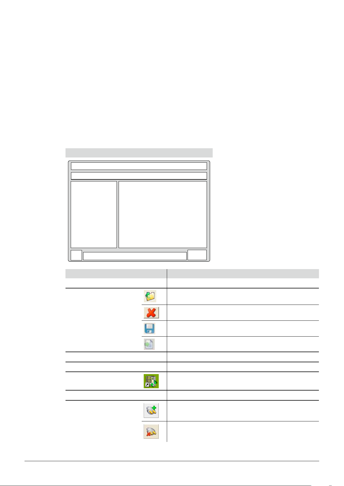
The concept drawing below displays the segmentation of the program window and the general icons.
The icon status depends on the actual program view:
Greyed-out icons are inactive and not operable•
Colored icons are active and operable•
Program window
4 Description of function
Position Icon Actions behind buttons
Menu bar
none Click on text, to activate drop down menus
Click this icon to open an existing extraction report
Click this icon to delete items
Toolbar with icons
Click this icon to safe items
Click this icon to export items in .csv format
Program tree view
Main view
Program icon
none To expand the tree-structure, click on the plus symbol
none Displays program information and configuration screens
Can be found on the desktop as a program shortcut
and in the program window
Progress bar
none Displays system status progress
PC is connected to the SpeedExtractor and
serial number of connected device (communication established)
Program status indication
PC is not connected to the SpeedExtractor (communication failed)
8 SpeedExtractor Record 1.0 Operation Manual, Version A
Page 9

4.2 Program structure overview
Program Entrance
Method Handling
Status
Reporting
Configuration
Visualization
Report handling
List of available reports
.
.
.
Main menu 1st submenu 2nd submenu Description and reference
4 Description of function
Start
Methods can be downloaded,
uploaded and configured
see section 4.3
Realtime visualization of the
SpeedExtractor system status
see section 4.4
Choice between ‘Visualization’ and
‘Report handling’
see section 4.5
Realtime extraction parameter
chart is displayed
see section 4.5.1
Open / save extraction reports and
empty report queue
see section 4.5.2
Reports are listed and directly
selectable for postprocessing
see section 4.5.2
Settings for user identification,
report logo and working directory
paths
see section 4.6
9 SpeedExtractor Record 1.0 Operation Manual, Version A
Page 10

4.3 Method handling
Methods are processing procedures for the SpeedExtractor. They contain the extraction processing
information like pressure, temperature, time and solvent.
Possible handling actions are:
Upload methods to the PC (e.g. for backup)•
Download methods to the SpeedExtractor (e.g. for restore)•
Configure or edit methods at the PC•
4.4 Status
The system state of the SpeedExtractor is visualized by an interface view. This interface has been
programmed to display the complex extraction cycles of the SpeedExtractor in terms of intuitive
reading. The user can follow every system status like valve positioning, extraction temperature and
pressure inside the extraction cells in realtime with ease.
4 Description of function
4.5 Reporting
Gives access to the below submenus.
4.5.1 Visualization
The ‘Visualization’ screen displays a realtime temperature and pressure chart. The stages including
stop, skip and error during extraction are indicated in the chart as well. In addition, all extraction and
method information are shown in a table. These information are used to generate the report.
4.5.2 Report handling
With every extraction, a report can be generated on the basis of previously recorded process data .
The ‘Report handling’ offers the following items:
New generated, • unsaved recordings (highlighted in red)
Unsaved extraction reports•
Previously saved extraction reports•
It is also possible to open a saved extraction report from file system and remove all reports in queue.
4.6 Configuration
The configuration item is used to configure the reports and to set working directories.
Available options are:
User identification (name, first name)•
Batch-no. for identification•
Logo in extraction report can be set•
The storage path of the • ‘Methods’, ‘Extraction reports’ and ‘Process data’ can be changed.
10 SpeedExtractor Record 1.0 Operation Manual, Version A
Page 11

5 Putting into operation
This section contains all steps to a working setup in chronologic order. If any errors occur, please
check every step carefully again from the beginning.
5.1 Step 1: Installing the program
The program must be installed on the PC following the installation guide on the CD-booklet.
The following prerequisites must be fulfilled:
For installation, the user must hold administrative rights on the computer•
The SpeedExtractor must be disconnected from the computer•
The PC must match the minimum system requirements for this software, see section 3.1•
5.2 Step 2: Connecting a SpeedExtractor
5 Putting into operation
To establish a connection, the following steps must be performed:
Switch on the SpeedExtractor and wait for its bootup process to be finished•
Use the delivered USB cable to connect the extractor to the PC. Check the program status •
indication icon for connection.
Note
The maximum cable length for USB cables without repeater must not exceed 5m
5.3 Step 3: Starting the program
To start the recording software, go to:
Start • > Programs > Buchi > SpeedExtractor Record1.0 > SpeedExtractor Record 1.0
Or double-click the program shortcut icon, which can be found on the desktop (see section 4.1)•
Note
The software is triggered to start recordings syncronized by the SpeedExtractor. Thus the software
must be started before performing an extraction! In case of a record interruption (e.g. loss of mains
power at the SpeedExtractor or broken communication) it is possible to store unfinished records.
11 SpeedExtractor Record 1.0 Operation Manual, Version A
Page 12

6 Operation
This section explains the different program views and handling steps.
6.1 Initial program view
After starting the program, the view below appears (Fig. 6.1). To expand the software tree in the
program tree window, click on the plus symbol.
6 Operation
Fig. 6.1: Main screen
The user has the choice to use the program tree window on the left or the blue hyperlinks of the main
view on the right to reach the different functions of the software.
12 SpeedExtractor Record 1.0 Operation Manual, Version A
Page 13

6.2 Method Handling
Fig. 6.2 shows the ‘Method handling’ view. This view offers an effective way to backup, add and
modify methods via the PC mouse and keyboard. Section 6.2.1 gives detailed information about the
handling possibilities in this view.
6 Operation
Fig. 6.2: Method Handling screen
Note
To get a short description of the items in this view, hold the mouse pointer over.
13 SpeedExtractor Record 1.0 Operation Manual, Version A
Page 14

6.2.1 Method handling view in detail:
The view is separated into different areas, which are listed and described as followed.
Working Directory:
To temporarily change the path of the ‘Working Directory’ on the PC, click on the folder icon and
choose the new storage / reading path for the methods.
Icon Actions behind buttons
Click to change storing path of methods temporarily
Note
The default storage path will be restored with every program restart! See section 6.5 for information
how to change the default system paths.
Methods On File System:
Methods stored on the PC file system are listed in the box. To select the listed methods, mark one or
more by mouse. It is also possible to start typing the first letters of a method for rapid access function.
By clicking the program icons the user can manipulate and create methods as listed below.
6 Operation
Icon Actions behind buttons
Select all methods in list
Create a new method
Delete selected methods from list
Refresh method list view
Print selected methods
Click this icon to safe a method
Additional icons for method exchange:
Methods can be transferred between the SpeedExtractor and the PC. Simply mark one or more
methods and click the corresponding icon to perform an upload or download action.
Icon Actions behind buttons
Upload selected methods from the SpeedExtractor to the PC
Download selected methods from the PC to the SpeedExtractor
Note
The method storage of the SpeedExtractor is limited to 100 entries. The maximum number of
methods to be stored on the PC is depending on the available harddisk space.
14 SpeedExtractor Record 1.0 Operation Manual, Version A
Page 15

6 Operation
Methods On Device:
Methods stored on the SpeedExtractor are listed in the box. To select the listed methods, mark one or
more by mouse. By clicking the program icons the user can manipulate and create methods as listed
below. If no SpeedExtractor is connected, this area stays inactive (greyed out).
Icon Actions behind buttons
Select all methods in list
Create a new method
Delete selected methods from list
Refresh method list view
Print selected methods (this includes all parameters)
Details Of Method:
This area displays all parameters of selected methods from the file system only.
To retrieve details from a stored method stored, first upload this item to the local file system!•
All indications are listed with their corresponding unit, including the amount of solvents, cycles and •
cycle details.
The list of solvents depends on the internal SpeedExtractor list. Due to technical limitations, •
changing solvents will not update the list on the SpeedExtractor!
Icon Actions behind buttons
Drop down arrow to select predefined options
Up / down arrows to increase or decrease values in predefined steps
Note
For details about specific method parameters, please refer to a corresponding method setup information.
15 SpeedExtractor Record 1.0 Operation Manual, Version A
Page 16

6.3 Status
The ‘Status’ view displays the SpeedExtractor system status in real-time. All important information are
visualized at a glance, thus as:
Note
No actions can be carried out here.
6 Operation
Number and position of active extraction cells•
System temperature, pressure and valve status•
Position valves with
pressure readings
at extraction positions 1 – 6
Temperature
heating block
Outlet valve
Pump pressure
Extraction position 1 – 6
Vial position 1 – 6
Waste
Solvent reservoir 1 – 4
with solvent valves
Solvent pump
Media valve
Fig. 6.3: Status view (E-916)
Note
This view is only visible when an instrument is connected.•
Vials and extraction cells are arranged in pairs. The number of available pairs depends on the type •
of SpeedExtractor (E-914 / E-916).
Filling levels can not be read out here!•
16 SpeedExtractor Record 1.0 Operation Manual, Version A
Page 17

6.4 Reporting
The ‘Reporting’ view offers entries for ‘Visualization’ and ‘Report handling’.
Description of offered program entry points:
‘Visualization’ to display temperature and pressure chart of the current measurement (see 6.4.1)•
‘Report handling’ to display temperature and pressure chart of previous measurements (see 6.4.2)•
To enter the program points, click the blue hyperlinks in the ‘Reporting’ view.
6 Operation
Fig. 6.4: ‘Reporting’ view
17 SpeedExtractor Record 1.0 Operation Manual, Version A
Page 18

6.4.1 Visualization
The ‘Visualization’ view displays a realtime pressure and temperature chart of the running extraction
process for recording. This includes any process interruption. It also shows details about the ongoing
extraction and its method.
Temperature and pressure chart
The legend in the upper right gives the corresponding colors and curve descriptions.
Additional chart features
Zoom-in feature:
Hold down the left mouse button and mark an area on the chart in a left-to-right, downwards •
directed movement.
Release the left mouse button, the previously marked area will appear zoomed.•
Zoom reset:
Hold down the left mouse button and drive the mouse-pointer in a right-to-left movement. This will •
reset the zoom.
Scrolling feature:
Hold down the right mouse button and move the mouse pointer on the chart area to move the •
chart freely.
6 Operation
Explanation Chart legend
The chart (Fig. 6.5) shows all possible events, highlighted by colors. Use the
checkboxes at the chart legend on the left to show or hide the different curves
or events.
Fig. 6.5: Visualization screen
Note
This view is only visible when an instrument is connected and an extraction is in process.
18 SpeedExtractor Record 1.0 Operation Manual, Version A
Page 19

Extraction information
The current extraction parameters and the detailed method information are displayed here. Changing
extraction parameters is not possible here.
6.4.2 Report handling
The ‘Reporting handling’ view offers three program entry points:
Click ‘Select Extraction report’, to select a new generated or previously opened extraction report •
via a drop-down menu
Click ‘Open Extraction report’, to open saved extraction reports from the file system•
Click ‘Remove all reports in queue’, to empty the report queue•
6 Operation
Fig. 6.6: Process Report screen
Select Extraction report
Use the drop-down menu for a listing or all reports created since the last software start-up and all
reports recently opened. Alternatively, use the list of reports in the program tree view. Click, to select a
specific report.
19 SpeedExtractor Record 1.0 Operation Manual, Version A
Page 20

6 Operation
Extraction Report Form
This pop-up window appears, after opening a red marked record entry. To create a useable extraction
report entry, fill out the form fields.
Note
Input fields marked with an asterisk (*) are mandatory and must be filled out.
Date and Time are automatically set to the
computer timebase.
Fill in the users data here.
The ‘Batch Nr.’ is a probe identification number.
The device ‘Serial Number’ is set automatically.
Use the ‘Notes’ box for any kind of extraction
related information.
To hide or show temperature and pressure
curve of the report, use the checkboxes under
Define Sequence to show in Report.
Fig. 6.7: Extraction Report Form
Note
A red record entry in the program tree view indicates a newly recorded data. To confirm the entry
and add a set of unique metadata, perform the following steps:
Click on the red entry (Fig. 6.6) and fill out the pop-up window ‘Extraction Report Form’ (Fig. 6.7)•
Subsequently, the extraction report is automatically created•
The report now appears in black with the previously chosen ‘Title of Report’.
Attention
Store the report on the file system after filling out the ‘Extraction Report Form‘! Otherwise, it will
remain in the queue and will be deleted after closing the program or emptying the queue!
20 SpeedExtractor Record 1.0 Operation Manual, Version A
Page 21

6 Operation
Open Extraction report
To access reports stored on the file system, click ‘Open Extraction report‘ for an explorer window
(Fig. 6.8). Choose the desired report by a mouse click and click ‘Open’ subsequently.
Fig. 6.8: Open Extraction Report
Note
If no reports appear in the explorer window, use the ‘Look in‘ drop-down menu to set the correct
path.
Remove all reports in queue
Click on the program entry link ‘Remove all reports in queue‘ to remove all non-saved reports created
since the last software start-up.
ATTENTION
Make sure to save the reports you want to keep before you click on ‘Remove all reports in queue‘ as
this function will unrecoverably delete all recently created reports and recordings.
21 SpeedExtractor Record 1.0 Operation Manual, Version A
Page 22

6.4.3 Extraction report
After opening up a report, view Fig. 6.9 appears. This view offers comprehensive editing and handling
possibilities that can be accessed via different program icons (see list of program icons below).
6 Operation
Fig. 6.9: Open Process Report
Program icon table (main window)
Icon Actions behind buttons
Open process reports folder to select a saved report
Delete the selected report from the report queue
Save the selected report on the file system
Export the selected report as .csv data for third party applications
(see also section 1.4 for list of abbreviations)
Note
All functions are available in the menu bar as well.
22 SpeedExtractor Record 1.0 Operation Manual, Version A
Page 23

6 Operation
Program icon table (‘Extraction report’ view)
Icon Actions behind buttons
Save the selected report on the file system
Print the selected report
Zoom out of the displayed report
Zoom into the displayed report
Go to the previous page of the displayed report
Go to the next page of the displayed report
About extraction reports
An ‘Extraction report’ can have several pages, depending on the amount of available information.
The report head contains details for its identification such as date and time, report title and the batchnumber of the probe.
The report body contains:
the process chart•
space for optional remarks•
a detailed list of the used method•
a list of the used cells•
the device serial number•
the event list•
For an example report, see following pages.
23
SpeedExtractor Record 1.0 Operation Manual, Version A
Page 24

Pressure [bar]
Temperature [°C]
Skip-event
Stop-period
Error-period
110
100
90
80
70
60
50
40
30
20
10
0
Time [hh:mm]
00:3500:3000:2500:2000:1500:1000:05
Pressure [bar]
Temperature [°C]
Skip-event
Stop-period
Error-period
110
100
90
80
70
60
50
40
30
20
10
0
Time [hh:mm]
00:3500:3000:2500:2000:1500:1000:05
Name: Dioxine_dust
Device type: E-916
Number of solvent ports: 2
Temperature: 100 °C
Pressure: 110 bar
Solvents: 100% Toluene
0%
Type of cell: 20 mL
Type of vial: 60 mL
Number of cycles: 2
Cycles:
Cycle 1: Hold time: 10 min
Discharge time: 1 min
Vial change: No
Cycle 2: Hold time: 10 min
Discharge time: 1 min
Vial change: No
Flush with solvent: 1 min
Flush with gas: 2 min
Used Method:
Remarks:
Serial Number of Device:
2403198299
This is a sample report.
This report shows the different possible information of a report.
For example an error period, a stop period, skip events or the note that a
cell was disabled during the extraction.
Used Cells:
1, 2
Position 3 disabled 00:16
Extraction report
Monday, 17 November 2008 11:25
Dioxine extraction (dust sample)
Batchnumber: 1232-a-0
Johan Kjeldahl
Page 1 of 2
Example report page 1 of 2
6 Operation
24 SpeedExtractor Record 1.0 Operation Manual, Version A
Page 25

Uncommon events during extraction:
Error-period start 00:00
Error-period end 00:00
Stop-period start 00:16
Stop-period end 00:17
Skip-event 00:17
Skip-event 00:33
Extraction report
Monday, 17 November 2008 11:25
Dioxine extraction (dust sample)
Batchnumber: 1232-a-0
Johan Kjeldahl
Page 2 of 2
Example report page 2 of 2
6 Operation
25
SpeedExtractor Record 1.0 Operation Manual, Version A
Page 26

6.5 Configuration
At the ‘Configuration’ view, program default settings can be adjusted.
6 Operation
Fig. 6.10: Configuration
Possible configuration settings
Activate the user defined radio buttons to change name, first name and batch-number of the user •
or use default settings instead.
At ‘Logo in extraction report’, use the radio buttons to change the report logo between the default •
company and a user defined one. When using a user defined logo, its position on the report can be
adjusted.
The ‘Working directories’ can be set independently for ‘Methods’, ‘Extraction reports’ and ‘Process •
data’. Use the folder button at the end of each directory path to open an explorer window. This
window allows you to choose a folder at will.
26 SpeedExtractor Record 1.0 Operation Manual, Version A
Page 27

7 Workflow
The section 7 is a step-by-step user guide for the software and extraction report handling.
7.1 Software startup conditions
To start the SpeedExtractor Record software, double-click the program shortcut on the desktop. Alter-
natively, you can start the program via the Windows start menu under programs (see section 5.3).
No Connection to SpeedExtractor established
If the SpeedExtractor is switched off or a communication problem (e.g. USB connection failure)
occurs, the program is limited to the following functions:
‘Method handling’ is only available for methods, stored on PC•
No SpeedExtractor system status is available in the ‘Status’ view•
In the ‘Reporting’ view, only stored extraction reports can be handled•
7 Workflow
Connection to SpeedExtractor is established
When the connection has been established successfuly, all software functionality is available to the
user.
If the connection has been established while the SpeedExtractor is already running an extraction the
software automatically recognizes this status. Then, the software offers the same reduced functionality
as listed above. Once the SpeedExtractor has finished its extraction process, all software functions
are available again.
Note
Changes in the ‘Configuration‘ view are possible in every software condition, but mostly require a
restart of the program to be done.
27 SpeedExtractor Record 1.0 Operation Manual, Version A
Page 28

7.2 While recording
The software automatically starts to record the system processing data once a new extraction has
been started.
The following views can be used to supervise the extraction process at the computer:
Visualization
During the recording process, use this view to supervise the extraction details as there are pressure,
temperature and progress indication in realtime.
Status
Use the ‘Status’ view for a realtime visualization of the technical status of the SpeedExtractor.
7.3 After recording
The recording is automatically stopped, once the SpeedExtractor finished its extraction or the extrac-
tion has been interrupted (e.g. loss of mains power at the SpeedExtractor or broken communication).
The user will be informed about it by a popup message.
7 Workflow
Fig. 7.1: Message Extraction done
7.4 Creating a report
As the message in Fig. 7.1 shows, to create a report some details have to be filled out first. Records,
which have not yet been saved are highlighted in red at the program tree area in the report queue.
Click on the checkmark to confirm
the message.
New recordings are highlighted in red.
Fig. 7.2: Message Extraction done
28 SpeedExtractor Record 1.0 Operation Manual, Version A
Page 29

7 Workflow
Report details
In the report queue, click on a red recording entry. This action brings up the ‘Extraction Report Form’
window (Fig. 7.3).
Date and Time are automatically set to the
computer timebase.
Fill in the users data here.
The ‘Batch Nr.’ is a probe identification number.
Fig. 7.3: Extraction Report Form
Click on this icon to confirm the form data (this will create a report, which has a black entry in the
report queue). The report is not yet saved on the file system!
Note
All data-fields marked with an asterisk (*) are mandatory. •
Save the report on the file system (see next section)!•
The device ‘Serial Number’ is set automatically.
Use the ‘Notes’ box for any kind of extraction
related information.
To hide or show temperature and pressure
curve of the report, use the checkboxes under
Define Sequence to show in Report.
29 SpeedExtractor Record 1.0 Operation Manual, Version A
Page 30

7.5 Further report processing
The new created report can be printed out, saved or exported as indicated by the table below.
7 Workflow
Icon
7.6 Method handling
In the ‘Method handling’ view, creation or modification of methods can be performed.
Creating a new method
Three steps are necessary to create a new method:
Step Click on this icon to create a new, empty method
Format
.xml =
.pdf = Portable document format (review is possible on computers, equipped with freely
.csv =
Description
Click on this icon to save the report as a .xml or as a .pdf-file.
Program internal data format (review will work with this program only)
available pdf-reader software)
Click on this icon to open the print dialogue
Click on this icon to export the report as a .csv-file
Comma separated export format, contains all measured values and can be
processed e.g. by spreadsheet programs
Step Name the method and adjust all parameter to your needs
Step Click on this icon to store the new method
30 SpeedExtractor Record 1.0 Operation Manual, Version A
Page 31

7.7 Method backup
It is recommended to make periodical backups of all methods, stored on the SpeedExtractor.
Performing a backup
Three steps are necessary to perform a method backup.
Step Click on this icon to select an appropriate file path for the backup
Step Click on this icon to select all methods at once
Step Click on this icon to transfer and store all methods on the file system
7 Workflow
Note
After the backup has been performed, you may have to set the ‘Working Directory‘ to the default
path.
31 SpeedExtractor Record 1.0 Operation Manual, Version A
Page 32

8 Troubleshooting
This section contains a list of frequently asked questions. Here you can find typical problems that
might occur during operation, whereby this list does not claim to be exhaustive.
8.1 FAQ
Is it possible to change any data in a stored record?1.
No, to avoid record manipulation this functionality is not available.
How many SpeedExtractor devices can be managed at the same time?2.
Due to technical limitations, only one device can be managed at a time.
The software does not record any data! What is wrong with it?3.
Check the program status indication icon. Make sure the SpeedExtractor is connected
to the PC (see also section 5).
8 Troubleshooting
Why does the software forget its Working Directory path after a restart, when it is set in the Method 4.
Handling view?
The Method Handling view only allows temporarily change of the path. To change
the path permanently, it must be changed in the Configuration view.
The liquid level in the Status view does not correspond with the real liquid level– why?5.
The liquid containers are dummy icons. Thus, these icons can not show the real liquid level.
I can not remember the functions behind the buttons. Where can I get these information easily?6.
To get a short description of items in a view, hold the mouse pointer over a button for a
second. This will work for most program elements.
How can I delete reports?7.
Use the Windows Explorer and choose your local ‚Working directory‘ path for the extraction
reports. It can be found at the ‚Configuration‘ view (see section 6.5).
Methods with new solvents, created on computer have been transferred to the SpeedExtractor 8.
successfully. But at the SpeedExtractor, the new solvent does not show up in the solvent list– why?
Due to technical limitations, solvents programmed on computer are not added to the Speed-
Extractors internal solvent list. They must be created at the SpeedExtractor directly, to be
available.
9. The device is connected to the computer. Why is it not possible to select and transfer methods to,
or from the SpeedExtractor?
Methods transfer is only possible when no extraction is beeing executed. Check, whether an
extraction is running first.
32
SpeedExtractor Record 1.0 Operation Manual, Version A
Page 33

Page 34

BÜCHI Labortechnik AG
CH-9230 Flawil 1 / Switzerland
T +41 71 394 63 63
F +41 71 394 65 65
www.buchi.com Quality in your hands
 Loading...