

Page 1

Operation Manual
Extraction Unit
E�812/816 SOX
093169
en
Page 2

Page 3

Table of contents
Table of contents
1 About this manual . . . . . . . . . . . . . . . . . . . . . . . . . . . . . . . . . . . . . . .5
1.1 Reference documents. . . . . . . . . . . . . . . . . . . . . . . . . . . . . . . . . .5
1.2 Abbreviations . . . . . . . . . . . . . . . . . . . . . . . . . . . . . . . . . . . . . . 5
2 Safety. . . . . . . . . . . . . . . . . . . . . . . . . . . . . . . . . . . . . . . . . . . . . .6
2.1 User qualification . . . . . . . . . . . . . . . . . . . . . . . . . . . . . . . . . . . . 6
2.2 Proper use . . . . . . . . . . . . . . . . . . . . . . . . . . . . . . . . . . . . . . . 6
2.3 Improper use . . . . . . . . . . . . . . . . . . . . . . . . . . . . . . . . . . . . . . 6
2.4 Safety warnings and safety signs used in this manual . . . . . . . . . . . . . . . . . . 7
2.5 Product safety. . . . . . . . . . . . . . . . . . . . . . . . . . . . . . . . . . . . . .9
2.5.1 General hazards. . . . . . . . . . . . . . . . . . . . . . . . . . . . . . . . . . . . .9
2.5.2 Warning labels on housing and assemblies . . . . . . . . . . . . . . . . . . . . . . 10
2.5.3 Personal protective equipment . . . . . . . . . . . . . . . . . . . . . . . . . . . . 10
2.5.4 Safety elements . . . . . . . . . . . . . . . . . . . . . . . . . . . . . . . . . . . . 11
2.6 General safety rules . . . . . . . . . . . . . . . . . . . . . . . . . . . . . . . . . . 11
3 Technical data . . . . . . . . . . . . . . . . . . . . . . . . . . . . . . . . . . . . . . . . 12
3.1 Scope of delivery . . . . . . . . . . . . . . . . . . . . . . . . . . . . . . . . . . . 12
3.1.1 Standard instrument. . . . . . . . . . . . . . . . . . . . . . . . . . . . . . . . . . 12
3.1.2 Standard accessories . . . . . . . . . . . . . . . . . . . . . . . . . . . . . . . . . 13
3.1.3 Optional accessories . . . . . . . . . . . . . . . . . . . . . . . . . . . . . . . . . 16
3.2 Technical data overview . . . . . . . . . . . . . . . . . . . . . . . . . . . . . . . . 17
3.3 Materials used. . . . . . . . . . . . . . . . . . . . . . . . . . . . . . . . . . . . . 17
4 Description of function . . . . . . . . . . . . . . . . . . . . . . . . . . . . . . . . . . . 18
4.1 Overview over the instrument . . . . . . . . . . . . . . . . . . . . . . . . . . . . . 18
4.2 Functional principle of a Soxhlet extraction . . . . . . . . . . . . . . . . . . . . . . 19
4.2.1 Step 1 - extraction . . . . . . . . . . . . . . . . . . . . . . . . . . . . . . . . . . 19
4.2.2 Step 2 - rinsing . . . . . . . . . . . . . . . . . . . . . . . . . . . . . . . . . . . . 20
4.2.3 Step 3 - drying . . . . . . . . . . . . . . . . . . . . . . . . . . . . . . . . . . . . 20
4.2.4 Solvent collection . . . . . . . . . . . . . . . . . . . . . . . . . . . . . . . . . . . 20
4.3 Controls of the Extraction Unit. . . . . . . . . . . . . . . . . . . . . . . . . . . . . 20
5 Putting into operation . . . . . . . . . . . . . . . . . . . . . . . . . . . . . . . . . . . . 21
5.1 Installation site. . . . . . . . . . . . . . . . . . . . . . . . . . . . . . . . . . . . . 21
5.2 Electrical connections . . . . . . . . . . . . . . . . . . . . . . . . . . . . . . . . . 22
5.3 Condensers . . . . . . . . . . . . . . . . . . . . . . . . . . . . . . . . . . . . . . 22
5.4 Soxhlet extractor . . . . . . . . . . . . . . . . . . . . . . . . . . . . . . . . . . . 23
5.5 Water supply connections. . . . . . . . . . . . . . . . . . . . . . . . . . . . . . . 23
5.6 Cooling water connection . . . . . . . . . . . . . . . . . . . . . . . . . . . . . . . 24
5.7 Cooling medium connection. . . . . . . . . . . . . . . . . . . . . . . . . . . . . . 25
5.7.1 Recirculating Chiller B-740/41 or equivalent model . . . . . . . . . . . . . . . . . . 25
5.7.2 Recirculating Chiller F-1xx . . . . . . . . . . . . . . . . . . . . . . . . . . . . . . . 25
5.8 Solvent hose connection . . . . . . . . . . . . . . . . . . . . . . . . . . . . . . . 26
3 E-812/816 Soxhlet Operation Manual, Version B
Page 4

Table of contents
6 Operation . . . . . . . . . . . . . . . . . . . . . . . . . . . . . . . . . . . . . . . . . . 27
6.1 Main screen . . . . . . . . . . . . . . . . . . . . . . . . . . . . . . . . . . . . . . 27
6.2 General information on buttons . . . . . . . . . . . . . . . . . . . . . . . . . . . . 28
6.3 Description of the menu functions . . . . . . . . . . . . . . . . . . . . . . . . . . . 29
6.3.1 Starting up the instrument. . . . . . . . . . . . . . . . . . . . . . . . . . . . . . . 29
6.3.2 Instrument settings . . . . . . . . . . . . . . . . . . . . . . . . . . . . . . . . . . 29
6.3.3 Occupying the positions. . . . . . . . . . . . . . . . . . . . . . . . . . . . . . . . 30
6.3.4 Defining a method. . . . . . . . . . . . . . . . . . . . . . . . . . . . . . . . . . . 31
6.3.5 Saving a method . . . . . . . . . . . . . . . . . . . . . . . . . . . . . . . . . . . 33
6.3.6 Opening a method . . . . . . . . . . . . . . . . . . . . . . . . . . . . . . . . . . 34
6.3.7 Deleting a method. . . . . . . . . . . . . . . . . . . . . . . . . . . . . . . . . . . 35
6.3.8 Abort function . . . . . . . . . . . . . . . . . . . . . . . . . . . . . . . . . . . . . 35
6.3.9 Skip function . . . . . . . . . . . . . . . . . . . . . . . . . . . . . . . . . . . . . 36
6.3.10 Service functions . . . . . . . . . . . . . . . . . . . . . . . . . . . . . . . . . . . 36
6.4 Example of an extraction process . . . . . . . . . . . . . . . . . . . . . . . . . . . 40
6.4.1 Material and equipment . . . . . . . . . . . . . . . . . . . . . . . . . . . . . . . . 40
6.4.2 Preparing an extraction . . . . . . . . . . . . . . . . . . . . . . . . . . . . . . . . 40
6.4.3 After the extraction process . . . . . . . . . . . . . . . . . . . . . . . . . . . . . . 41
6.4.4 Emptying the solvent tank . . . . . . . . . . . . . . . . . . . . . . . . . . . . . . . 41
6.4.5 Reusing the solvent . . . . . . . . . . . . . . . . . . . . . . . . . . . . . . . . . . 41
7 Maintenance . . . . . . . . . . . . . . . . . . . . . . . . . . . . . . . . . . . . . . . . . 42
7.1 Daily maintenance. . . . . . . . . . . . . . . . . . . . . . . . . . . . . . . . . . . 42
7.1.1 Housing . . . . . . . . . . . . . . . . . . . . . . . . . . . . . . . . . . . . . . . . 42
7.1.2 Hoses and hose connections . . . . . . . . . . . . . . . . . . . . . . . . . . . . . 42
7.1.3 Glass parts . . . . . . . . . . . . . . . . . . . . . . . . . . . . . . . . . . . . . . 42
7.1.4 Solvent tank. . . . . . . . . . . . . . . . . . . . . . . . . . . . . . . . . . . . . . 43
7.2 Weekly maintenance . . . . . . . . . . . . . . . . . . . . . . . . . . . . . . . . . 44
7.2.1 Heating elements . . . . . . . . . . . . . . . . . . . . . . . . . . . . . . . . . . . 44
7.3 Monthly maintenance . . . . . . . . . . . . . . . . . . . . . . . . . . . . . . . . . 44
7.3.1 Cleaning the seals. . . . . . . . . . . . . . . . . . . . . . . . . . . . . . . . . . . 44
7.3.2 Replacing the seals . . . . . . . . . . . . . . . . . . . . . . . . . . . . . . . . . . 44
7.3.3 Condenser . . . . . . . . . . . . . . . . . . . . . . . . . . . . . . . . . . . . . . 45
7.3.4 Flushing the tank valve . . . . . . . . . . . . . . . . . . . . . . . . . . . . . . . . 45
7.4 Customer service . . . . . . . . . . . . . . . . . . . . . . . . . . . . . . . . . . . 45
8 Troubleshooting . . . . . . . . . . . . . . . . . . . . . . . . . . . . . . . . . . . . . . . 46
8.1 Malfunctions and their remedy. . . . . . . . . . . . . . . . . . . . . . . . . . . . . 46
8.2 Error messages . . . . . . . . . . . . . . . . . . . . . . . . . . . . . . . . . . . . 47
8.3 Too high/too low results . . . . . . . . . . . . . . . . . . . . . . . . . . . . . . . . 48
9 Shutdown, storage, transport and disposal . . . . . . . . . . . . . . . . . . . . . . . . 49
9.1 Preparing the instrument for storage and transport . . . . . . . . . . . . . . . . . . 49
9.2 Storage and transport . . . . . . . . . . . . . . . . . . . . . . . . . . . . . . . . . 49
9.3 Disposal. . . . . . . . . . . . . . . . . . . . . . . . . . . . . . . . . . . . . . . . 50
10 Spare parts. . . . . . . . . . . . . . . . . . . . . . . . . . . . . . . . . . . . . . . . . . 51
11 Declarations and requirements. . . . . . . . . . . . . . . . . . . . . . . . . . . . . . . 52
11.1 FCC requirements (for USA and Canada) . . . . . . . . . . . . . . . . . . . . . . . 52
11.2 Declaration of conformity . . . . . . . . . . . . . . . . . . . . . . . . . . . . . . . 53
4 E-812/816 Soxhlet Operation Manual, Version B
Page 5

1 About this manual
This manual describes the Extraction Unit E-812/816 SOX and provides all information required for its
safe operation and to maintain it in good working order.
It is addressed to laboratory personnel and operators in particular.
Read this manual carefully before installing and running your system and note the safety precautions
in section 2 in particular. Store the manual in the immediate vicinity of the instrument, so that it can be
consulted at any time.
No technical modifications may be made to the instrument without the prior written agreement of
BUCHI. Unauthorized modifications may affect the system safety or result in accidents. Technical data
are subject to change without notice.
NOTE
The symbols pertaining to safety are explained in section 2.
1 About this manual
This manual is copyright. Information from it may not be reproduced, distributed or used for competitive purposes, nor made available to third parties. The manufacture of any component with the aid of
this manual without prior written agreement is also prohibited.
The English manual is the original language version and serves as basis for all translations into
other languages. If you need another language version of this manual, you can download available
versions at www.buchi.com.
1.1 Reference documents
For information on the Extraction Unit E-812/816 Hot Extraction, please refer to the corresponding
manuals as PDF on CD available in English, German, French, Italian and Spanish
• Extraction Unit E-812/816 Hot Extraction, Operation Manual number 93164 - 93168
1.2 Abbreviations
FEP: Fluorinated Ethylene Propylene
FPM: Fluorpolymer rubber
PMMA: Polymethyl methacrylate
PP: Polypropylene
PTFE: Ethylenetetrafluoroethylene
PVDF: Polyvinylidene difluoride
5 E-812/816 Soxhlet Operation Manual, Version B
Page 6

2 Safety
This chapter points out the safety concept of the instrument and contains general rules of behavior
and warnings from hazards concerning the use of the product.
The safety of users and personnel can only be ensured if these safety instructions and the safetyrelated warnings in the individual chapters are strictly observed and followed. Therefore, the manual
must always be available to all persons performing the tasks described herein.
2.1 User qualification
The instrument may only be used by laboratory personnel and other persons who on account of
training or professional experience have an overview of the dangers which can develop when
operating the instrument.
Personnel without this training or persons who are currently being trained require careful instruction.
The present Operation Manual serves as the basis for this.
2 Safety
2.2 Proper use
The instrument has been designed and built for laboratories. It serves for activities associated with fat
extraction.
It is used for:
• Soxhlet extraction with diethyl ether, hexane, petroleum ether and chloroform.
2.3 Improper use
Applications not mentioned above are improper. Also, applications, which do not comply with the
technical data, are considered improper. The operator bears the sole risk for any damages caused by
such improper use.
The following uses are expressly forbidden:
• Use of the instrument in rooms which require ex-protected instruments.
• Determination of samples, which can explode or inflame (example: explosives, etc.) due to shock,
friction, heat or spark formation.
• Use in overpressure situations.
• Use with other glassware than the original from BUCHI.
• Use with other solvents than diethyl ether, hexane, petroleum ether or chloroform.
• Use with more than the allowed maximum solvent amount (max. 150 ml).
• Use with samples that react with solvent.
6 E-812/816 Soxhlet Operation Manual, Version B
Page 7

2.4 Safety warnings and safety signs used in this manual
DANGER, WARNING, CAUTION and NOTICE are standardized signal words for identifying levels of
hazard seriousness of risks related to personal injury and property damage. All signal words, which are
related to personal injury are accompanied by the general safety sign.
For your safety it is important to read and fully understand the table below with the different signal
words and their definitions!
Sign Signal word Definition Risk level
!
DANGER
Indicates a hazardous situation which, if not avoided, will result in
death or serious injury.
2 Safety
★★★★
WARNING
!
CAUTION
!
NOTICE
no
Supplementary safety information symbols may be placed in a rectangular panel on the left to the
signal word and the supplementary text (see below example).
Space for
supplementary
safety
information
symbols.
Table of supplementary safety information symbols
The reference list below incorporates all safety information symbols used in this manual and their
meaning.
Indicates a hazardous situation which, if not avoided, could result
in death or serious injury.
Indicates a hazardous situation which, if not avoided, may result
in minor or moderate injury.
Indicates possible property damage, but no
practices related to personal injury.
!
SIGNAL WORD
Supplementary text, describing the kind and level of hazard / risk seriousness.
• List of measures to avoid the herein described, hazard or hazardous situation.
• ...
• ...
(property damage only)
★★★☆
★★☆☆
★☆☆☆
Symbol Meaning
General warning
Electrical hazard
Heavy weight, avoid overexertion
7 E-812/816 Soxhlet Operation Manual, Version B
Page 8

Symbol Meaning
Harmful to life-forms
Pinch point, mechanical hazards
Fire hazard
Hot item, hot surface
2 Safety
Device damage
Inhalation of substances
Chemical burns by corrosives
Wear laboratory coat
Wear protective goggles
Wear protective gloves
Heavy weight, lifting requires more than one person
Additional user information
Paragraphs starting with Note transport helpful information for working with the device / software or its
supplementaries. Notes are not related to any kind of hazard or damage (see following example).
8 E-812/816 Soxhlet Operation Manual, Version B
Page 9

NOTE
Useful tips for the easy operation of the instrument / software.
2.5 Product safety
The Extraction Unit is designed and built in accordance with state-of-the-art technology. Nevertheless, risks to users, property, and the environment can arise when the instrument is used carelessly or
improperly.
The manufacturer has determined residual dangers emanating from the instrument
• if the instrument is operated by insufficiently trained personnel.
• if the instrument is not operated according to its proper use.
Appropriate warnings in this manual serve to make the user alert to these residual dangers.
2.5.1 General hazards
Pay attention to the following safety notices:
!
WARNING
Death or serious injuries by formation of explosive atmospheres inside the instrument.
• Before operation, check all tube connections for correct installation
• Check for proper system tightness
2 Safety
!
DANGER
Death or serious injuries by use in explosive environments.
• Do not store or operate the instrument in explosive environments
• Provide sufficient ventilation and make sure to directly withdraw fumes
!
WARNING
Death or serious burns by flammable vapors.
• Remove all sources of flammable vapors
• Do not store flammable chemicals in the vicinity of the device
!
CAUTION
Risk of burns by hot heating glass plate (up to 250°C).
• Do not touch hot parts or surfaces
• Let the system and inserted extraction cells cool down safely
• Do not move the instrument or parts of it when hot
Risk of instrument damage by liquids or mechanical shocks.
• Do not spill liquids over the instrument or its components
• Do not move the instrument when it is loaded with sample liquid
• Do not drop the instrument or its components
• Keep external vibrations away from the instrument
• Safely attach the instrument to the bench in earthquake prone regions
• Do not operate the instrument without the safety shield installed
NOTICE
9 E-812/816 Soxhlet Operation Manual, Version B
Page 10

2 Safety
Risk of instrument damage by wrong mains supply.
• External mains supply must meet the voltage given on the type plate
• Check for sufficient grounding
2.5.2 Warning labels on housing and assemblies
The following warning sticker(s) can be found on the housing or assemblies of the instrument:
Symbol Meaning Location
Hot item, hot surface Sticker / label, located at the heating block
2.5.3 Personal protective equipment
Always wear personal protective equipment such as protective eye goggles, protective clothing and
gloves. The personal protective equipment must meet all requirements of the supplementary data
sheets for the chemicals used.
NOTICE
!
WARNING
Serious chemical burns by corrosives.
• Observe supplementary data sheets of all used chemicals.
• Handle corrosives in well ventilated environments only.
• Always wear protective goggles.
• Always wear protective gloves.
• Always wear protective clothes.
• Do not use damaged glassware.
10 E-812/816 Soxhlet Operation Manual, Version B
Page 11

2.5.4 Safety elements
Electronics
• The heating element is equipped with an electronic over-temperature protection.
• If no cooling water is detected at the cooling water output (for example, due to a leak in the
condenser), the electronic over-protection will stop all processes.
• To start a program at least one extraction position must be activated in the software.
• Safety shield: The protective shield protects operators from broken glass, solvent splashes and
prevents burns from the hot plates.
• Safety shield sensor: To start an extraction the protective shield must be closed.
Optional
• The protective shield (optional accessory) for the condenser protects operators from broken glass
in case of an accident or explosion.
2.6 General safety rules
2 Safety
Responsibility of the operator
The head of laboratory is responsible for training his personnel.
The operator shall inform the manufacturer without delay of any safety-related incidents which might
occur during operation of the instrument. Legal regulations, such as local, state and federal laws
applying to the instrument must be strictly followed.
Duty of maintenance and care
The operator is responsible for ensuring that the instrument is operated in proper condition only, and
that maintenance, service, and repair jobs are performed with care and on schedule, and by authorized personnel only.
Spare parts to be used
Use only genuine consumables and genuine spare parts for maintenance to assure good system
performance and reliability. Any modifications to the spare parts used are only allowed with the prior
written permission of the manufacturer.
Modifications
Modifications to the instrument are only permitted after prior consultation with and with the written
approval of the manufacturer. Modifications and upgrades shall only be carried out by an authorized
BUCHI technical engineer. The manufacturer will decline any claim resulting from unauthorized modifications.
11 E-812/816 Soxhlet Operation Manual, Version B
Page 12

3 Technical data
This chapter introduces the reader to the instrument specifications. It contains the scope of delivery,
technical data, requirements and performance data.
3.1 Scope of delivery
Check the scope of delivery according to the order number.
NOTE
For detailed information on the listed products, see www.buchi.com or contact your local dealer.
3.1.1 Standard instrument
3 Technical data
Table 3-1: Standard instrument
Product Order number
Extraction Unit E-816 Soxhlet
(6 place; 100 - 120 VAC / 200 - 240 VAC;
50/60 Hz; 1950/1200 W)
Extraction Unit E-812 Soxhlet
(2 place; 100 - 120 VAC / 200 - 240 VAC;
50/60 Hz; 700/1200 W)
47581
49111
12 E-812/816 Soxhlet Operation Manual, Version B
Page 13

3.1.2 Standard accessories
2
3
3 Technical data
Table 3-2: Standard accessories
1
E-812 E-816 Product Order number
1 1 Beaker pliers, 50 mm a 02004
1 1 Pliers for glass sample tubes with frit
4
b
47609
1 1 Turix wrench c 44349
5 5 Hose clamp, Ø 10.1 mm d 28737
- 1 Holder for 6 beakers (for E-816) 47643
1 3 Set of glass sample tubes, 2 pieces 49430
1 1 Set of holders for glass sample tubes
49432
with frits, set of 6 pieces
1 3 Set of beakers Soxhlet, 2 pieces 49427
1 3 Set of Soxhlet glass chamber, 2 pieces 49452
13 E-812/816 Soxhlet Operation Manual, Version B
Page 14

3 Technical data
Table 3-2: Standard accessories (cont.)
E-812 E-816 Product Order number
2 2 Paper thimbles 25 x 100 mm,
41882
set of 6 pieces
2 2 Paper thimbles 33 x 94 mm,
41883
set of 6 pieces
1 1 Set of holders for paper thimbles
49428
25 x 100 mm, 6 pieces
1 1 Set of holders for paper thimbles
49429
33 x 94 mm, 6 pieces
1 1 Boiling stones, 10 g 42864
1 1 Plastic funnel 51167
1 1 Hose adapter for cooling media input 49151
1 1 Cooling water hose complete,
37780
G3/4”, G1/2”, L = 1.5 m
1 1 Solvent hose, Tygon SE 200, 1 m a 49450
1 1 PTFE hose, 500 mm b 25315
2
1
14 E-812/816 Soxhlet Operation Manual, Version B
Page 15

3 Technical data
Table 3-2: Standard accessories (cont.)
E-812 E-816 Product Order number
3
1
5
2 2 Knurled screw (for solvent hose) a 43237
2 2 Clamping ring (for solvent hose) a 43238
4
2
5 5 Hose clamp, Ø 9.6 mm b 27738
2 2 Hose, silicone, Ø 6/9
43940
L = 1.5 m c
2 2 Condenser connection hose, silicone,
49161
L = 0.35 m, mounted
1 5 Condenser hose, silicone, L = 0.20 m
49163
d
2 2 Hose coupling (wide and small) e 43565
2 6 Set of seals, Viton, 2 pieces 49431
2 6 Seal PVDF holder 47610
1 1 Set of seals PTFE 49433
1 1 Sound absorber 15641
2 6 Glass valve unit complete 47590
1 1 Power cable
Type CH 10010
Type Schuko 10016
Type GB 17835
Type USA 10020
Type AUS 17836
1 1 Operation Manual E-812/816 SOX
English 93169
German 93170
French 93171
Italian 93172
Spanish 93173
15 E-812/816 Soxhlet Operation Manual, Version B
Page 16

3.1.3 Optional accessories
3 Technical data
Table 3-3: Optional accessories
Product Order number
Holder for glass sample tubes, microwavable (6 positions), PTFE
Holder for glass sample tubes,
(4 positions), PP
Condenser complete, including connector,
straight
49424
37462
47604
Protective shield E-816 SOX 51923
Protective shield E-812 SOX 51968
Expansion element 51957
16 E-812/816 Soxhlet Operation Manual, Version B
Page 17

3.2 Technical data overview
Table 3-4: Technical data
Dimensions (L x H x D) 275 x 776 x 456 mm 635 x 776 x 456 mm
Connection voltage 100 - 120 VAC / 200 - 240 VAC
Power consumption max. 700/1200 W max. 1950/1200 W
Weight 21 kg 36 kg
Overvoltage category II II
Pollution degree 2 2
Environmental conditions
Temperature
Altitude
Humidity
3 Technical data
Extraction Unit E-812 Soxhlet Extraction Unit E-816 Soxhlet
100 - 120 VAC / 200 - 240 VAC
± 10%, 50/60 Hz
for indoor use only
5 – 40 °C
up to 2000 m above sea level
maximum relative humidity 80% for
temperatures up to 31 °C, and then
linearly decreasing to 50% at 40 °C
± 10%, 50/60 Hz
for indoor use only
5 – 40 °C
up to 2000 m above sea level
maximum relative humidity 80% for
temperatures up to 31 °C, and then
linearly decreasing to 50% at 40 °C
3.3 Materials used
Table 3-5: Materials used
Component Material designation Material code
Housing Stainless steel
Glass parts Borosilicate glass 3.3
Axial seal FPM 80-Shore A 170-A
Solvent hose inside instrument FEP DN 3.18/2.18; FEP DN 8/6
Solvent hose Tygon with FEP veneer
Solvent tank Borosilicate glass 3.3
Solvent valve and valve piston Body: Al Mg Si Sn Bi (Stanal-32)
Cooling media hoses Silicone
Condenser holder PVDF
Heating plate Ceran-Hightrans
Protective shield PMMA transparent green 777
Membrane glass valve Fluorez
Surface: Ematal, plane, high corrosive-compressed
®
17 E-812/816 Soxhlet Operation Manual, Version B
Page 18

4 Description of function
This chapter explains the basic principle of the instrument, shows how it is structured and gives a
functional description of the assemblies.
4.1 Overview over the instrument
4 Description of function
1
a Condensers
b Protective shield
c Soxhlet extraction chambers with sample tube
Fig. 4.1: Overview over the instrument
2
3
4
5
6
d Beaker
e Heating plate
f Operating panel
18 E-812/816 Soxhlet Operation Manual, Version B
Page 19

4.2 Functional principle of a Soxhlet extraction
The Extraction Unit E-812/816 Soxhlet is designed to extract fat quickly and product-friendly from
food and feed. Thereby the sample is extracted in running cycles. The extraction process consists of 3
steps decribed in the following.
1
1
2
3
4 Description of function
4
6
a Cooling water
b Receiving funnel
c Solvent tank connection
Fig. 4.2: Schematic overview over an extraction position
4.2.1 Step 1 - extraction
The solvent evaporates and the vapor rises up to the condenser. From there the condensed solvent
flows into the 10 ml receiving funnel. When the receiver is full, the solvent flows back into the sample
through the 5 holes of the receiving funnel.
The tank valve and the glass valve are closed.
The solvent level increases up to the optical sensor. The sample is extracted.
The optical sensor detects the solvent level and opens the glass valve. The solvent containing the
extract flows back into the solvent beaker.
When the programmed number of cycles is reached and /or if the extraction time is over the system
goes to the next step.
5
7
d Optical sensor
e Soxhlet extraction chamber with glass sample tube
f Magnetic glass valve
g Beaker
19 E-812/816 Soxhlet Operation Manual, Version B
Page 20

4.2.2 Step 2 - rinsing
The glass valve is open. The condensed solvent flows into the receiving funnel, drops down into the
extraction chamber and flows back into the beaker.
When the programmed rinsing time is over, the system goes to the next step.
4.2.3 Step 3 - drying
The tank valve is open and removes the solvent. In the end the extract is dried as much as possible.
The glass valve is still open.
4.2.4 Solvent collection
After the extraction is finished, all solvent is collected in the tank.
4.3 Controls of the Extraction Unit
1
2
2 2
3
4
2
4 Description of function
a Display
b Functional buttons
c START button
d STOP button
5
e Selection knob
Fig. 4.3: Controls of the Extraction Unit
20 E-812/816 Soxhlet Operation Manual, Version B
Page 21

5 Putting into operation
This chapter describes how the instrument is installed and gives instructions on initial startup.
NOTE
Inspect the instrument for damages during unpacking. If necessary, prepare a status report immediately to inform the postal company, railway company or transportation company.
Keep the original packaging for future transportation.
5.1 Installation site
Put the instrument on a stable, horizontal surface. Consider the maximum product dimensions and
weight. Conform to the environmental conditions as described in section 3.2, technical data.
Installation prerequisites:
• Do not place any objects on top or below the instrument.
• The instrument must be installed with 5 cm clearance from any other objects or walls to allow
sufficient cooling.
• Do not store containers, chemicals or other items behind the instrument.
5 Putting into operation
!
WARNING
Death or serious injuries by use in explosive environments.
• Do not operate the instrument in explosive environments
• Do not operate the instrument with explosive gas mixtures
• Before operation, check all gas connections for correct installation
• Directly withdraw released gases and gaseous substances by sufficient ventilation
CAUTION
!
Risk of minor or moderate injury by heavy weight of the instrument.
• Consult three further persons to transport the instrument
• Do not drop the instrument
• Place the instrument on a stable, even and vibration-free surface
• Keep limbs out of crushing zone
Risk of instrument damage by liquids or mechanical shocks.
• Do not spill liquids over the instrument or its components
• Do not move the instrument when it is loaded with sample liquid
• Do not drop the instrument or its components
• Keep external vibrations away from the instrument
• Safely attach the instrument to the bench in earthquake prone regions
• Do not operate the instrument without the protection cover installed at the front
NOTICE
21 E-812/816 Soxhlet Operation Manual, Version B
Page 22

5.2 Electrical connections
NOTE
External connections and extension lines must be provided with a grounded conductor lead (3-pole
couplings, cord or plug equipment). All used power cords must meet the input power requirements.
5 Putting into operation
5.3 Condensers
To install the glass condensers proceed as follows:
• Dip your fingertip into distilled water and run over the black O-ring of the receiving funnel. Make
sure that no water drops remain in the funnel.
• Carefully put the condenser into the receiving funnel.
Risk of instrument damage by wrong mains supply.
• External mains supply must meet the voltage given on the type plate
• Check for sufficient grounding
NOTICE
Fig. 5.1: Installing the glass components
22 E-812/816 Soxhlet Operation Manual, Version B
Page 23

5.4 Soxhlet extractor
a
b
Fig. 5.2: Adjusting the Soxhlet chambers
To adjust the Soxhlet chambers, proceed as follows:
1. Move the rack up.
2. Pull the tray out.
3. Remove the safety shield by loosing the screws on the side of the instrument.
4. Remove the sealing holder from the extraction chambers.
5. Fix the magnet valve at the glass valve of the extraction chamber (b).
6. Connect the magnetic valve cable to the instrument (a).
7. Place the extraction chamber in position (d) and fix it with the sealing holder (e). Make sure that
the PTFE sealing ring is in correct position.
8. Adjust the optical sensor (c). It detects the solvent level. The solvent must cover the sample
during the extraction process. To achieve the optimum extraction efficiency adjust the optical
sensor directly above the sample.
9. Fix the safety shield after having fixed all extraction chambers.
5 Putting into operation
e
d
c
5.5 Water supply connections
The condensers have to be connected in series.
• Condensers connected in
series.
First connect the cooling water hoses (two longer hoses) to the rear panel. Put a hose clamp over the
cooling water hose. Take a pincer to fix the hose clamp. Begin with the left condenser position. Screw
it into the collection vessel (see chapter 5.3 Condensers) and connect the cooling water hoses (hose
clamp and GL-14 plug). To connect them among each other use the short hoses.
NOTE
Do not forget the grommet otherwise cooling water may leak.
• For safety reasons, secure the hoses with pivoting clamps.
• To save cooling water use a chiller.
• Fixing the clamp. • Hose with pivoting connec-
tion and clamp.
23 E-812/816 Soxhlet Operation Manual, Version B
Page 24

5.6 Cooling water connection
Connect the cooling water to the cooling water input a. The cooling water hose has to be secured
on both the instrument and the water connection side by means of hose clamps. The water pressure
should have a maximum of 4 bar. The built in valve reduces the water flow to 1.2 liters per minute.
The flanged screw coupling for the water connection has a standard screw thread of G 3/4“.
2
5 Putting into operation
a Cooling water input
b Cooling water output
1
Fig. 5.3: Cooling water connection
Fix the silicon hose to the cooling water output b. The drain hose for the cooling water should be
placed directly into the drain. For this purpose, shorten the silicone hose to the optimal length. The
drain hose should not show any kinks, sharp bends and/or siphoning effect. Prevent flooding inside
and outside the instrument by securing the drain hose.
Check the cooling water hoses for bends.
To save water the instrument switches off the flow 5 minutes after the extraction has ended.
NOTE
The condensers can be filled with cooling medium in the Service mode. In this case, proceed as
follows:
• Change to the service mode (click Menu, go to Mode and change from Extraction to Service, then
confirm with OK).
• Open the cooling medium valve (click Menu, go to Service functions, then to Valve testing, select
Cooling water and press Open).
• Open the cooling medium flow (open the water tap).
• After all condensers are filled with cooling medium, close the valve again and set the instrument
back to the Extraction mode (click Menu, go to Mode and change from Service to Extraction, then
confirm with OK).
NOTE
The temperature of the cooling water must be at least 25 °C below the boiling point of the organic
solvent used. If this is not possible use a chiller.
24 E-812/816 Soxhlet Operation Manual, Version B
Page 25

5.7 Cooling medium connection
5.7.1 Recirculating Chiller B-740/41 or equivalent model
When you operate with a BUCHI Recirculating Chiller B-740/41 or an equivalent model of another
manufacturer, use the adapter (see figure below) to connect the water input to the chiller output. Make
sure, that the axial seal is inserted.
A temperature of 10 °C is recommended.
• Adapter • Axial seal within the adapter
5 Putting into operation
5.7.2 Recirculating Chiller F-1xx
To connect the chiller models F-1xx to the extraction unit use the chiller connection set (article no.
11058415).
NOTE
F-100: to be used with one E-812, F-108: to be used with one E-816 or two E-812, F-114: to be
used with two E-816.
Fig. 5.3: Cooling water connection with mounted chiller connection set
Before starting an extraction make a test start to fill the condensers as the flow control unit for
cooling water gets no signal until all condensers are filled. Fill the condensers with cooling medium as
described in the chapter “Cooling water connection”.
25 E-812/816 Soxhlet Operation Manual, Version B
Page 26

5.8 Solvent hose connection
Fix the solvent hose to the solvent connection on the left of the instrument by pushing it on the
connector and tightening the knurled screw.
Fig. 5.6: Solvent hose connection
The solvent hose consists of two parts, a transparent Tygon hose (with FEP veneer) and a white PTFE
hose. The PTFE hose is solvent resistant, thus it has to be inserted into the Tygon hose.
5 Putting into operation
NOTE
Only the PTFE hose must come into contact with solvent, see picture below.
The solvent container should be placed in a
lower position than the instrument.
Fig. 5.7: PTFE hose in the solvent container
26 E-812/816 Soxhlet Operation Manual, Version B
Page 27

6 Operation
This chapter gives examples of typical instrument applications and instructions on how to operate the
instrument properly and safely.
6.1 Main screen
6 Operation
11
9
12
10
8
1
Fig. 6.1: Display elements on the main screen
2
a Functional button to open the solvent tank valve
b Functional button to open the main menu
c Functional button to move the rack down
d Symbol for the heating (on or off)
e Symbol for the solvent tank valve (open/close)
f Symbol for cooling medium valve (open/close)
g Symbol for cooling medium running (on/off)
h Current beaker situation (Extraction, Rinsing,
7
6
5
4
Drying, Beaker active, Beaker inactive Error,
Abort) with position number
i Remaining time for the running method
j Extraction step / status
k Selected solvent / operation mode
l Method name
3
27 E-812/816 Soxhlet Operation Manual, Version B
Page 28
6.2 General information on buttons
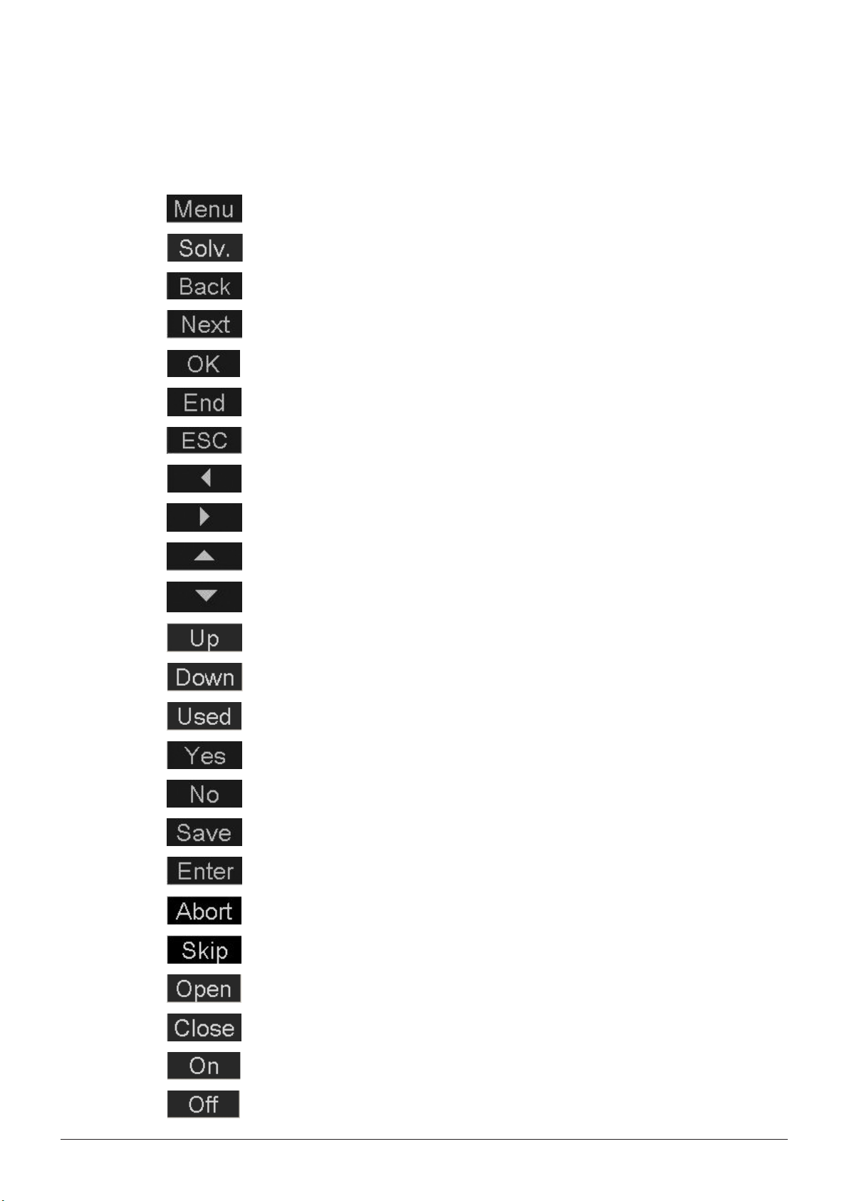
The following control buttons are available in the software for navigation and input confirmation:
Open the main menu
Open the solvent valve and thus emptying the solvent tank
Get back to the previous screen
Get on to the next screen
Confirm and save a setting and get back to the main / previous screen
Leave the current screen and get back to the main screen
Get back to the start screen without saving possible settings
6 Operation
Backward button to move backward within in the submenu structure
Forward button to move forward within in the submenu structure
Move up within the entries of a screen
Move down within the entries of a screen
Move rack up
Move rack down
When entering a name for a method the names of already existing methods can be found when
pressing the button
Affirm a screen message
Negate a screen message
Save a program under the entered name
Confirm the entry of a character when naming a program
Abort a single position during an extraction process
Skip the process to the next step
Open a valve for test purposes
Close a valve for test purposes
Switch the pump on for test purposes / switch the sound off
Switch the pump off for test purposes / switch the sound off
28 E-812/816 Soxhlet Operation Manual, Version B
Page 29

6.3 Description of the menu functions
6.3.1 Starting up the instrument
Make sure, that the instrument is correctly connected to the mains supply and the cooling water. Then
switch on the instrument at the main switch. The main screen appears:
6 Operation
Fig. 6.1: Main screen
6.3.2 Instrument settings
To define the instrument settings, press the Menu button. The following screen opens:
Fig. 6.2: Menu
Select instrument settings and press the forward button.
Fig. 6.3: Instrument settings
29 E-812/816 Soxhlet Operation Manual, Version B
Page 30

You can now change the settings by turning the selection knob and pressing OK to confirm. Press the
move up or move down button to switch between the settings. When the Beep key function is on, a
beep sound is audible whenever a key is pressed. When the Beep end function is on a beep sound is
audible when the extraction process is finished.
Max. cycle time: If a cycle is not reached after this time, an error message apears.
Standard setting: 30 min.
Press the backward button to get back to the main menu.
6.3.3 Occupying the positions
To occupy the positions, press the Menu button. The following screen opens:
6 Operation
Fig. 6.4: Menu
Select Occupied positions and press the forward button. The software will now ask you whether you
want to occupy all positions or not. To occupy all positions, press Yes. You will then get back to the
main menu and the positions 1 to 6 are occupied and ready for use.
If you do not want to occupy all but only some manually defined positions, press No. The following
screen appears:
Fig. 6.5: Occupied positions
You can now switch individual positions by turning the selection knob and pressing OK. Press the
backward button to get back to the main menu.
30 E-812/816 Soxhlet Operation Manual, Version B
Page 31

6.3.4 Defining a method
In the main menu select Program. The following screen opens:
Fig. 6.6: Extraction solvent
You can now select the desired solvent by turning the selection knob.
6 Operation
NOTE
The Extraction Unit is only tested with the solvents petroleum ether, diethyl ether, chloroform and
hexane. The use of other solvents can be done by choosing “Custom” but is on the risk of the user.
Please check chemical resistance of all parts in contact with the solvent prior to use.
Press OK to confirm and then Next to proceed with the Extraction step.
Fig. 6.7: Extraction step
Set the extraction time and/or the number of cycles by means of the selection knob and press OK to
confirm it.
NOTE
If the extraction time and the number of cycles are programmed, both criteria need to be fulfilled to
go to the next step.
Positions that have fulfilled the criteria will be heated until the last position has fulfills the criteria as
well.
If you have to change the default heater setting, you can regulate it between 50 - 110%. Use the
default setting for general extraction purposes.
Press Next to proceed with the Rinse step.
31 E-812/816 Soxhlet Operation Manual, Version B
Page 32

6 Operation
Fig. 6.8: Rinse step
Set the rinse time by means of the selection knob and press OK to confirm it.
NOTE
We recommend to use the default heater setting of 100% for general extraction purposes.
Press Next to continue with the drying step.
Fig. 6.9: Drying step
Set the drying time by means of the selection knob and press OK to confirm it.
NOTE
We recommend to use the default heater setting of 100% for general extraction purposes.
Your method is now created. Press End to get back to the menu.
32 E-812/816 Soxhlet Operation Manual, Version B
Page 33

6.3.5 Saving a method
Define a method according to the chapter “Defining a method” and save it as follows:
In the main menu select File.
Fig. 6.10: Main screen
Press the forward button to get to the submenu File.
6 Operation
Fig. 6.11: File
Press the forward button to enter a name for your new method.
Fig. 6.12: Enter name
Use the selection knob to select the letters for the name and press Enter each time. To delete a letter,
select BACKSPACE and then Enter.
When you have finished, press Save to save the name. You will get back to the submenu File.
33 E-812/816 Soxhlet Operation Manual, Version B
Page 34

NOTE
To overwrite an existing method, select Used and press OK. To carry out minor changes in the
method name, select Used, select the name you want to change, carry out the changes and press
OK.
6.3.6 Opening a method
In the File submenu go to Open.
6 Operation
Fig. 6.13: File
Select the method you want to open with the selection knob and press OK. The method now appears
on the main screen ready for carrying out a corresponding extraction process.
Fig. 6.14: Main screen with selected program
34 E-812/816 Soxhlet Operation Manual, Version B
Page 35

6.3.7 Deleting a method
In the File submenu go to Delete.
Fig. 6.15: File
Select the method you want to open with the selection knob and press OK. A message appears
asking you whether you really want to delete this program. Press Yes to confirm and the backward
button to get back to the main menu.
6 Operation
6.3.8 Abort function
It is possible to abort a specific position during an extraction process. For all other positions the
extraction is continued. For this purpose, press Abort. The first defined beaker symbol starts flashing.
Select the position you want to abort by means of the selection knob and press Abort.
Fig. 6.16: Abort
35 E-812/816 Soxhlet Operation Manual, Version B
Page 36

6.3.9 Skip function
During the extraction process it is possible to skip one step and go directly to the next step, e.g. from
the extraction step to the rinse step. For this purpose, press Skip and confirm the appearing message
by pressing Yes.
Fig. 6.17: Skip
6 Operation
6.3.10 Service functions
In the main menu the submenu Service functions is available. Here you have an overview over all
sensors, functional efficiency of the valves, heating elements, information on the extraction unit and
the operating hours. Part of this information (all testing functions) is only available in the Service mode.
To change to the Service mode proceed as follows:
In the main menu select Mode, turn the selection knob to Service and press OK.
Fig. 6.18: Go to the Service Mode
Now go to the Service functions with the move up button and press the forward button. The following
screen appears:
36 E-812/816 Soxhlet Operation Manual, Version B
Page 37

Fig. 6.19: Service functions
Heater testing
Select Heater temperatures.
6 Operation
Fig. 6.20: Heater temperatures
Here you get an overview over the current temperatures at the individual heating positions.
NOTE
The indicated temperature is the temperature within the heating element, not on top of the heating
plate.
To get back to the Service functions press the backward button.
37 E-812/816 Soxhlet Operation Manual, Version B
Page 38

6 Operation
Valve testing
Select Valve testing. The following screen opens:
Fig. 6.21: Valve testing
You can now test the functioning of the three valves by changing their status. For this purpose, select
a valve and press Open or Close. You will hear a corresponding sound and see a corresponding reaction, depending on your setup.
NOTE
Close all valves before you leave this submenu, otherwise it is not possible to start an extraction.
NOTE
The tank valve may overheat if it is open for more than 10 s, the valve therefore closes after 10 s and
cannot be reopened for another 20 s afterwards.
To get back to the Service functions press the backward button.
Sensor testing
Select sensor testing. The following screen opens:
Fig. 6.23: Sensor testing
The “X” behind the sensor name signalizes that the sensor is activated. This is the case when:
• the solvent tank is completely full (Solvent)
• the cooling water is flowing (Flow)
• the protective shield is down (Shield)
For the rack, the “X” has a special meaning:
• Pos. up: [X] Pos. down [X]: Rack is up
38 E-812/816 Soxhlet Operation Manual, Version B
Page 39

• Pos. up: [ ] Pos. down [ ]: Rack is down
• Pos. up: [ ] Pos. down [X]: Rack is in between
To get back to the Service functions press the backward button.
Operating hours
Select operating hours. The following screen opens:
6 Operation
Fig. 6.24: Operating hours - 1
Here you see the operating hours of each heating position. To see the second page press Next. The
following screen appears:
Fig. 6.25: Operating hours - 2
Here you can see for how many hours the instrument was switched on, how many extractions were
carried out already and what extraction time was needed up to now.
To get back to the Service functions press the backward button.
39 E-812/816 Soxhlet Operation Manual, Version B
Page 40

Unit information
Select unit information. The following screen opens:
Fig. 6.26: Unit information
Here you get a short overview over technical instrument data.
6 Operation
6.4 Example of an extraction process
6.4.1 Material and equipment
Before starting an extraction process all necessary materials and chemicals must be present:
• Fume hood (only when working with diethyl ether or chloroform)
• Cooling water connection
• Analytical balance (± 0.1 mg; minimal weight 200 g)
• Spatula
• Funnel
• Desiccator
• Solvent
• 2 or 6 beakers
• 2 or 6 glass sample tubes or thimbles
• Waste container for organic solvents
• Depending on the application: Silica sand, celite, glass wool and paper thimbles
NOTE
The holders for the glass sample tubes and the paper thimbles are not microwavable.
6.4.2 Preparing an extraction
To prepare the instrument for extraction, proceed as follows:
1. Dry the clean solvent beakers with three boiling stones each in the drying oven for 30 minutes, let
the beakers cool down to ambient temperature in the desiccator and weigh them.
2. Prepare the sample as required in the glass sample tubes with frits or in the paper thimbles, e.g.
hydrolysis and/or drying.
3. Place the prepared glass sample tube or paper thimble with the corresponding holder in the
extraction chamber.
4. Adjust the optical sensor above sample level.
5. Fill the organic solvent directly into the beakers.
40 E-812/816 Soxhlet Operation Manual, Version B
Page 41

6. Place the beakers on the corresponding positions directly on the heating plate.
7. Lower the rack.
8. Activate the occupied positions.
9. Select a previous program or enter a new one.
10. Open the cooling water flow or switch on the connected chiller.
11. Start the extraction process.
6.4.3 After the extraction process
The end of an extraction process is indicated on the display and audible by a beep sound (if selected
in the instrument settings).
After an extraction process is finished, proceed as follows:
• Confirm the message on the screen by pressing the backward button.
• Empty the solvent tank.
• Move up the rack.
• Carefully remove the glass tubes or thimbles from the beakers by means of the pliers.
• Place the glass sample tubes or thimbles on a tissue and let them dry under the fume hood.
• Dry the beakers in a drying oven at 100 °C or in a vacuum oven at 200 mbar and 70 °C until they
have a constant weight.
• Let the beakers cool down to ambient temperature in a desiccator.
• Weigh the beakers and calculate the resulting fat content.
6 Operation
6.4.4 Emptying the solvent tank
• To empty the solvent tank put the solvent outlet hose into the waste container.
• Press Solv. and confirm the appearing message by pressing Yes.
NOTE
Make sure to empty the solvent tank after each extraction.
6.4.5 Reusing the solvent
• The solvent can be reused directly or after being distilled in a rotary evaporator.
When the instrument was used for the first time:
• Waste the solvent
When a different solvent was used before
• Waste the solvent
After incorrect procedure:
• Clean the glass assembly
• Clean the solvent tank
• Waste the solvent
NOTE
When working with petroleum ether from 40 - 60 °C: Renew the whole solvent after 10 extractions
to achieve a reproducible extraction behaviour. The mixture changes within time because the light
fraction evaporates and the heavy fraction accumulates.
41 E-812/816 Soxhlet Operation Manual, Version B
Page 42

7 Maintenance
This chapter gives instructions on all maintenance work to be performed in order to keep the instrument in good working condition.
7 Maintenance and repairs
WARNING
!
Death or serious burns by electric current at cleaning.
• Switch off the instrument
• Disconnect the power cord and prevent unintentional restart
• Wait until the instrument is completely dry before reconneting to mains
Risk of housing and instrument damage by liquids and detergents.
• Do not spill liquids over the instrument or parts of it
• Wipe off any liquids instantly
• Use ethanol or soapy water as detergent only
NOTICE
7.1 Daily maintenance
7.1.1 Housing
Check the housing for defects (switches, plugs) and clean it regularly with a damp cloth.
7.1.2 Hoses and hose connections
Check the hoses and hose connections for defects (cracks, brittle areas) and replace damaged hoses
immediately.
7.1.3 Glass parts
Visually inspect all glass parts for defects (cracks, stars, and splintering) regularly.
Beakers
After extraction, rinse the beakers with hot water and dish washing liquid and use a brush to clean
them thoroughly. Subsequently wash them in a laboratory dish washer.
Sample tubes
Empty the sample tubes into a waste and rinse them with water. They can be washed in a dish
washer as well. Make sure that they do not get in contact with the metal cones.
All glass parts, except for the condenser spiral, must be clean and dry before they are used again. The
glass parts can be dried in a drying oven at 100 °C for 30 minutes or in a vacuum oven at 70 °C for 20
minutes. Afterwards let the glass parts cool down slowly before reusing them, as they are under too
high tension when they are warm/hot.
42 E-812/816 Soxhlet Operation Manual, Version B
Page 43

7.1.4 Solvent tank
Empty the solvent tank after each extraction process. The solvent in the tank can be reused when
the extraction process was normal. In case of an incident during the extraction, the solvent can be
cleaned e.g. in a rotary evaporator.
NOTE
In case you empty the tank after you have already filled in the solvent for the next extraction, be
aware that the 10 ml of solvent in the receiving funnel are withdrawn as well, because the tank valve
has to be opened to empty the solvent tank.
In case it is not possible to empty the solvent tank automatically because of a software breakdown,
the instrument has to be opened manually by the emergency opening. For this purpose, proceed as
follows:
7 Maintenance and repairs
• Unscrew all screws on the back side of the
instrument and remove the back cover.
Fig. 7.1: Emptying the solvent tank manually
• Loosen the outer left screw cap (solvent feed
from the collection valve to the tank) and lift it
a little as to provide air to the system.
• Provide a vessel to collect the outflowing
solvent.
• Remove the solvent screw on the left bottom
side by means of a hexagonal socket or a flat
pincer.
43 E-812/816 Soxhlet Operation Manual, Version B
Page 44

7.2 Weekly maintenance
7.2.1 Heating elements
The ceramic heating plates should be cleaned regularly after they have cooled down. Remove dirt
adhering to the plate with e.g. ethanol. Then clean the plate with a moist cloth and dry it.
7.3 Monthly maintenance
7.3.1 Cleaning the seals
NOTE
When replacing the seals, take care not to damage them. To avoid damaging the seals, never apply
grease and never touch them with sharp objects.
To prolong the lifetime of the seals, rinse them regularly with distilled water. Afterwards, dry them with
a soft cloth.
7 Maintenance and repairs
7.3.2 Replacing the seals
Seals are subject to wear and tear, thus you should check them regularly and replace them, if necessary.
To replace the seals on the extraction chambers, proceed as follows:
• Remove the protective shield.
• Slide the rack forward, so that you have free access to the extraction chambers.
• Remove the extraction chamber for which you want to replace the seal.
• Now proceed as shown in the figures below:
Fig. 7.2: Replacing the seals on the extraction chambers
• Now refix the extraction chamber, slide back the rack and remount the protective shield.
To replace the seals on the beakers, proceed as shown in the figures belows:
44 E-812/816 Soxhlet Operation Manual, Version B
Page 45

Fig. 7.3: Replacing the seals on the beakers
7.3.3 Condenser
Unscrew the condenser connections, remove the condenser and place it in a laboratory dish washer
for cleaning with a conventional agent.
Use an appropriate cleaner to remove possible contaminations adhering to the condenser spiral, e.g.
algae. Let the spiral soak for a while.
7 Maintenance and repairs
NOTE
To remove the condensers moisten the seal with water.
7.3.4 Flushing the tank valve
The tank valve has to be flushed in regular intervals to prevent clogging.
For this purpose, we recommend to carry out an extraction process with fresh solvent at least every
six months (or earlier, denpending on your extraction processes and frequency).
7.4 Customer service
Only authorised service personnel are allowed to perform repair work on the instrument. These
persons have a comprehensive technical training and knowledge of possible dangers which might
arise from the instrument.
Addresses of official BUCHI customer service offices are given on the BUCHI website under:
www.buchi.com. If malfunctions occur on your instrument or you have technical questions or application problems, contact one of these offices.
The customer service offers the following:
• Spare part delivery
• Repairs
• Technical advice
45 E-812/816 Soxhlet Operation Manual, Version B
Page 46

8 Troubleshooting
This chapter helps to resume operation after a minor problem has occurred with the instrument. It lists
possible occurrences, their probable cause and suggests how to remedy the problem.
The troubleshooting table below lists possible malfunctions and errors of the instrument. The operator
is enabled to correct some of those problems or errors by him/herself. For this, appropriate corrective
measures are listed in the column “Corrective measure”.
The elimination of more complicated malfunctions or errors is usually performed by a BUCHI technical
engineer who has access to the official service manuals. In this case, please refer to your local BUCHI
customer service agent.
8.1 Malfunctions and their remedy
Table 8-1: General malfunctions and their remedy
Malfunction Possible cause Corrective measure
Instrument does not work Incorrect or no mains connection Connect the instrument correctly to the mains
Instrument not switched on Switch on the instrument
Method cannot be started Service mode active Change to Extraction mode
Rack is in upper position Lower the rack
Solvent tank is full Empty the tank
Protective shield is open Close the protective shield
Software does not show the main
screen
Method stops Cooling water flow is too low Check the cooling water connection and all
Cooling water sensor is defective (may be the feeding water is
contaminated with algae, lime, etc.)
Evaporation of extraction
solvent
Boiling retardation Incorrect positioning of the beaker Place the beaker directly onto the heating plate
No boiling Incorrect positioning of the beaker Place the beaker directly onto the heating plate
Seals wrong, deformed or
damaged
Spring deflection downwards Contact the BUCHI customer service
Incorrect positioning of the beaker/
glassware and seals
No anti-bumping granules were
used
Beaker position is not active
8 Troubleshooting
supply
Go back to the main screen
hoses for bends and remove them, if necessary
Contact the BUCHI customer service
Exchange the seals
Contact the BUCHI customer service
Put anti-bumping granules into the beakers
Activate the beaker position
Heater power is set too low
Elution of celite Too much organic solvent for
extraction
Sand/celite layers mixed up Clean the extraction chambers
46 E-812/816 Soxhlet Operation Manual, Version B
Use 100% for general purpose
Choose correct solvent
Stick to the standard application parameters
Page 47

Table 8-1: General malfunctions and their remedy (cont.)
Malfunction Possible cause Corrective measure
Empty solvent tank not
possible
8.2 Error messages
NOTE
In the following table X refers to the position in the instrument starting from left to right.
Table 8-2: Error messages
Error number Display information Possible cause Corrective measure
0001 No cooling water flow detected.
Please verify if a proper flow is
possible
0002 Please close safety shield
completely
0003 The Line Voltage is too low Voltage is out of the range Make sure the power supply is
0004 The Line Voltage is too high Voltage is out of the range Make sure the power supply is
0005 Rack not in rear position The rack is not properly
0006 Heating malfunction. Please
contact service
0010 to
0015
0020 Error during extraction process:
0021 to
0026
0051 Error during rack positioning.
0053 to
0058
0077 to
0082
0083 Solvent tank is full. Please empty
any other - Technical errors Contact the BUCHI customer service
Extraction stopped on position
X. Soxhlet cycle has not been
completed
All tasks stopped
Overtemperature Heater X:
Heater was turned off
Motor was shut off
Transfer valve at position X is not
connected
Malfunction of heater at position X
occurred. Please check heater
tank and restart again.
8 Troubleshooting
Software breakdown Retry to empty the solvent tank. If this does not
work, manually empty the tank by opening the
emergency opening
No cooling water started or
Open the cooling water flow
connected
Safety shield is open Close safety shield correctly
stable and start again
stable and start again
Bring rack in upper position and
pushed back to rear
push it back to rear position
position
Heating defective Contact the BUCHI customer service
Maximum cycle time is
exceeded
Check for possible leakages and add
solvent
Error during process Start again
Overtemperature on
respective position
Cool down the heating and start
again
Motor error Contact the BUCHI customer service
Transfer valve not
connected
Check plug connection at the instrument
Heater defective Contact the BUCHI customer service
Solvent tank was not
cleared. There is too much
Empty solvent tank by pressing the
button “Solv.”
solvent in the tank
47 E-812/816 Soxhlet Operation Manual, Version B
Page 48

8.3 Too high/too low results
There are many reasons for too high or too low results even though the extraction process ran without
problems. The most important reasons are listed in the following:
Results too high
• Work with clean and dry hands and material (weighing and sample preparation).
• Dry the beakers completely after extraction until a constant weight is reached.
• Use clean and pure solvent.
• Make sure that the components in contact with solvent are out of solvent resistant material (solvent
resistant funnel, dispensette organic, for example).
Results too low
• Insufficient sample homogenisation
• Sample was wet before extraction.
• Fat is combusted during drying due to high temperature in the drying oven.
• Use clean and pure solvent.
Problems during hydrolysis with B-411/E-416
• If the hydrolysing temperature is too high fat of sample can combust or the sample solution can
boil over.
• If the hydrolysing time is too long sample fat might be destroyed.
• If the hydrolysing time is too short the fat is not unhinged completely of the matrix.
• If the temperature of the rinsing water (hydrolysis) is too hot, fat is washed out.
• If the celite content is too small the sample fat can not be bounded sufficiently.
• Fat can combust during too hot drying (too high temperature/power in microwave, drying oven or
vacuum drying oven).
8 Troubleshooting
48 E-812/816 Soxhlet Operation Manual, Version B
Page 49

9 Shutdown, storage, transport and disposal
9 Shutdown, storage, transport and disposal
This chapter instructs how to shut down the instrument, how to pack it for storage or transport, and
specifies the storage and shipping conditions.
9.1 Preparing the instrument for storage and transport
To prepare the instrument for storage and transport, lower the rack, unplug the power cord, remove
the cooling water, and remove all glass parts from the instrument.
Emptying the condenser
Place the cooling water out hose into a drain. Disconnect the silicon hose (cooling water in) at the rear
of the instrument and place it into a waste container. Loosen the upper condenser screws by half a
turn.
Dismantling the condenser
Moisten the connection between condenser and holder before removing the condenser.
By doing so, turn it a little.
Emptying the solvent tank
Make sure, that the solvent tank is empty before transporting the instrument.
9.2 Storage and transport
Store the instrument at a dry place. Store and transport the instrument in its original packaging.
!
Death or serious poisoning by contact or incorporation of harmful substances.
• Wear safety goggles
• Wear safety gloves
• Wear a laboratory coat
• Flush the instrument and clean all accessories thoroughly to remove possibly dangerous
substances
• Do not clean dusty parts with compressed air
• Store the instrument and its accessories at a dry place in its original packaging
WARNING
49 E-812/816 Soxhlet Operation Manual, Version B
Page 50

9.3 Disposal
To dispose of the instrument in an environmentally friendly manner, a list of materials is given in
chapter 3. This helps to ensure that the components are separated and recycled correctly.
Please follow valid regional and local laws concerning disposal.
9 Shutdown, storage, transport and disposal
CAUTION
!
Risk of minor or moderate injury by heavy weight of the instrument.
• Consult three further persons to transport the instrument
• Do not drop the instrument or its transport box
• Place the instrument on a stable, even and vibration-free surface
• Keep limbs out of crushing zone
50 E-812/816 Soxhlet Operation Manual, Version B
Page 51

10 Spare parts
This chapter lists spare parts, accessories, and options including their ordering information.
Order the spare parts from BUCHI. Always state the product designation and the part number when
ordering spare parts.
Use only genuine BUCHI consumables and genuine spare parts for maintenance and repair to assure
good system performance and reliability. Any modifications to the spare parts used are only allowed
with the prior written permission of the manufacturer.
Table 10-1: Spare parts
Product Order number
Plastic funnel 51167
Beaker pliers, 50 mm 02004
Turix wrench 44349
Pliers for glass sample tubes with frit 47609
Hose adapter for cooling media input 49151
Hose coupling (wide and small) 43565
Hose clamp 28737
Cooling water hose complete, G3/4”, G1/2”, L = 1.5 m 37780
Hose, silicone Ø 6/9, L = 1.5 m 43940
Solvent hose, Tygon SE 200 49450
PTFE hose 500 mm 25315
Knurled screw (for solvent hose) 43237
Clamping ring (for solvent hose) 43238
Condenser connection hose, silicone, L = 0.35 m 49161
Condenser hose, silicone, L = 0.20 m 49163
Set of holders for glass sample tubes with frits, set of 6 pieces 49432
Set of holders for paper thimbles, 25 x 100 mm, 6 pieces 49428
Set of holders for paper thimbles, 33 x 94 mm, 6 pieces 49429
Holder for 6 beakers (for E-816) 47643
Set of beakers Soxhlet, 2 pieces 49427
Set of beakers Soxhlet, 12 pieces 45675
Condenser complete, including connector, straight 47604
Protective shield E-816 SOX 51923
Protective shield E-812 SOX 51968
Set of seals, Viton, 2 pieces 49431
Set of sealing ring PTFE SOX, 6 pieces 49433
Holder for glass sample tubes, micro-wavable, 6 positions, PTFE 49424
Solvent hose Soxhlet, including coupling 49164
Set of Soxhlet glass chamber, 2 pieces 49452
Glass valve unit, complete 47590
Sound absorber 15641
Membrane with anchor for glass valve 37534
Chiller connection set 11058415
IQ/OQ-set E-812/816 SOX 45657
10 Spare parts
51 E-812/816 Soxhlet Operation Manual, Version B
Page 52

11 Declarations and requirements
11.1 FCC requirements (for USA and Canada)
English:
This equipment has been tested and found to comply with the limits for a Class A digital device,
pursuant to both Part 15 of the FCC Rules and the radio interference regulations of the Canadian
Department of Communications. These limits are designed to provide reasonable protection against
harmful interference when the equipment is operated in a commercial environment.
This equipment generates, uses and can radiate radio frequency energy and, if not installed and used
in accordance with the instruction manual, may cause harmful interference to radio communications.
Operation of this equipment in a residential area is likely to cause harmful interference in which case
the user will be required to correct the interference at his own expense.
Français:
Cet appareil a été testé et s'est avéré conforme aux limites prévues pour les appareils numériques
de classe A et à la partie 15 des réglementations FCC ainsi qu’à la réglementation des interférences
radio du Canadian Department of Communications. Ces limites sont destinées à fournir une protection adéquate contre les interférences néfastes lorsque l’appareil est utilisé dans un environnement
commercial.
Cet appareil génère, utilise et peut irradier une énergie à fréquence radioélectrique, il est en outre
susceptible d’engendrer des interférences avec les communications radio, s’il n’est pas installé et
utilisé conformément aux instructions du mode d’emploi. L’utilisation de cet appareil dans les zones
résidentielles peut causer des interférences néfastes, auquel cas l’exploitant sera amené à prendre les
dispositions utiles pour palier aux interférences à ses propres frais.
11 Declarations and requirements
52 E-812/816 Soxhlet Operation Manual, Version B
Page 53

11.2 Declaration of conformity
11 Declarations and requirements
53 E-812/816 Soxhlet Operation Manual, Version B
Page 54

Page 55

Page 56

BÜCHI Labortechnik AG
CH-9230 Flawil 1 / S witzerlan d
T +41 71 394 63 63
F +41 71 394 65 65
www.buchi.com Quality in your hands
 Loading...