

Page 1

BROOKFIELD DV-I PRIME
Digital Viscometer
Operating Instructions
Manual No. M/07-022-D0613
Page 2

Page 3

TABLE OF CONTENTS
I. INTRODUCTION ..................................................................................................5
I.1 Components .................................................................................................................................................6
I.2 Utilities ............................................................................................................................................................7
I.3 Components and Dimensions ...............................................................................................................8
I.4 Specications ............................................................................................................................................ 10
I.5 Setup ............................................................................................................................................................ 11
I.6 Safety Symbols and Precautions ........................................................................................................ 11
I.7 Key Functions ............................................................................................................................................ 12
I.8 Preventative Maintenance and Cleaning ........................................................................................ 13
II. GETTING STARTED ............................................................................................ 14
II.1 Auto Zero .................................................................................................................................................... 14
II.2 Spindle Selection ..................................................................................................................................... 15
II.2.1 Spindle Selection for Models WITHOUT Temperature Display ....................................15
II.2.2 Spindle Section for Models WITH Temperature Display ................................................. 16
II.3 Speed Selection & Setting .................................................................................................................... 17
II.4 Autorange .................................................................................................................................................. 18
II.5 CGS or SI Units Selection ....................................................................................................................... 19
II.6 Temperature Display in °F or °C .......................................................................................................... 19
II.7 Out of Range ............................................................................................................................................. 19
II.8 Operation ................................................................................................................................................... 20
II.9 Timed Modes for Viscosity Measurement ....................................................................................... 21
II.9.1 Set Up ............................................................................................................................................... 21
II.9.2 Timed Stop ...................................................................................................................................... 21
II.9.3 Time to Torque ............................................................................................................................... 23
II.9.4 Temperature Oset ...................................................................................................................... 25
II.10 Print Modes ............................................................................................................................................. 26
II.11 Communication with Wingather Software ................................................................................. 27
II.12 Math Models .......................................................................................................................................... 31
II.12.1 The Power Law (Ostwald) Model .......................................................................................... 31
II.12.2 The Herschel-Bulkley Model .................................................................................................. 32
II.12.3 The Bingham Model ..................................................................................................................34
II.12.4 The Casson Model ......................................................................................................................35
II.12.5 Other Common Rheological Models .................................................................................. 37
III. MAKING VISCOSITY MEASUREMENTS ........................................................... 39
III.1 Quick Start ................................................................................................................................................. 39
III.2 Preparations for Making Measurements ...................................................................................... 39
III.3 Selecting a Spindle/Speed ................................................................................................................. 40
III.4 Multiple Data Points ............................................................................................................................. 40
Page 4

Appendix A - Cone/Plate Viscometer Set-Up ........................................................................ 42
Appendix B - Viscosity Ranges .................................................................................................... 47
Appendix C - Variables in Viscosity Measurement ............................................................... 51
Appendix D - Spindle and Model Codes ................................................................................. 53
Appendix E - Calibration Check Procedures ........................................................................... 55
Appendix F - The Brookeld Guardleg ..................................................................................... 62
Appendix G - Communications .................................................................................................. 64
Appendix H - Laboratory Stands with Parts Identication ............................................... 65
Appendix I - DVE-50A Probe Clip ............................................................................................... 67
Appendix J - Fault Diagnosis and Troubleshooting ............................................................. 68
Appendix K - Online Help and Additional Resources ......................................................... 69
Appendix L - Warranty Repair and Service ............................................................................. 70
Appendix M - Viscosity Test Report ........................................................................ 71(tear out page)
Brookeld Engineering Laboratories, Inc. Page 4 Manual No. M/07-022-D0613
Page 5

I. INTRODUCTION
Tp
Tp
The Brookeld DV-I PRIME Viscometer measures uid viscosity at given shear rate. Viscosity
is a measure of a uid’s resistance to ow. You will nd a detailed description of the science of
viscosity in the Brookeld publication “More Solutions to Sticky Problems”, a copy of which
was included with your DV-I PRIME.
The principle of operation of the DV-I PRIME is to drive a spindle (which is immersed in the test
uid) through a calibrated spring. The viscous drag of the uid against the spindle is measured by
the spring deection. Spring deection is measured with a rotary transducer. This system provides
continuous sensing and display of the measurement during the entire test. The measurement range
of a DV-I PRIME (in centipoise or milliPascal-seconds) is determined by the rotational speed
of the spindle, the size and shape of the spindle, the container the spindle is rotating in, and the
full-scale torque of the calibrated spring.
There are four basic spring torque series offered by Brookeld:
Spring Torque
Model dyne-cm milli Newton-m
LVDV-I
RVDV-I
HADV-I
HBDV-I
PRIME 673.7 0.0673
PRIME 7,187.0 0.7187
PRIME 14,374.0 1.4374
PRIME 57,496.0 5.7496
The higher the torque calibration, the higher the measurement range. The viscosity measurement
range for each torque calibration may be found in Appendix B.
Spring torque decals, on peel-off labels, are being supplied with your instrument. Please select
the appropriate decal and attach to the viscometer.
The DV-I PRIME is available with a built-in temperature probe option, which allows temperature
readout over the range -100ºC to +300ºC (-148ºF to + 572ºF). This option allows ambient
temperature measurement or temperature measurement of the sample during viscosity testing.
Contact Brookeld or your local Brookeld agent for more information on this instrument option.
All units of measurement are displayed according to either the CGS system or the SI system.
1. Viscosity appears in units of centipoise (shown as “cP”) or milliPascal-seconds (shown
as mPa•s) on the DV-I PRIME Viscometer display.
2. Torque appears in units of dyne-centimeters or Newton-meters (shown as percent “%”)
in both cases) on the DV-I PRIME Viscometer display.
3. Temperature appears in units of Celsius (shown as C) or Fahrenheit ( shown as F) on the
DV-I PRIME Viscometer display.
The following applies to DV-I PRIME Viscometers with the temperature probe option. Look for
the symbol
Viscometers with temperature probe option.
throughout this manual for instructions pertaining specically to DV-I PRIME
Brookeld Engineering Laboratories, Inc. Page 5 Manual No. M/07-022-D0613
Page 6

The equivalent units of measurement in the SI system are calculated using the following
Tp
conversions:
SI CGS
Viscosity: 1 mPa•s = 1 cP
7
Torque: 1 Newton-m = 10
dyne-cm
References to viscosity throughout this manual are done in CGS units. The DV-I PRIME
Viscometer provides equivalent information in SI units.
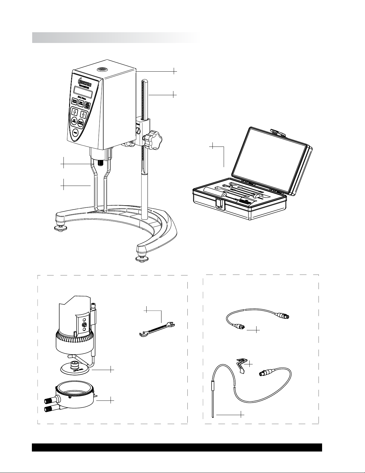
I.1 Components
Component Part Number Quantity
DV-I PRIME varies 1
Model G Laboratory Stand Model G 1
Spindle Set with Case* varies 1
LVDV-I PRIME set of four spindles (#61 through #64) (SSL)
RVDV-I PRIME set of six spindles (#02 through #07) (SSR)
HA/HBDV-I PRIME set of six spindles (#02 through #07) (SSH)
Shipping Cap* B-30-3Y 1
Power Cord (115V/230V) DVP-65/66 1
Guardleg* (not supplied with HA/HB versions) varies 1
LVDV-I PRIME B-20Y
RVDV-I PRIME B-21Y
Carrying Case DVE-106 1
Operating Manual M07-022 1
Torque Decals T05-1012 1
For cone/plate versions
Spindle wrench CP-23 1
Cone spindle CPE-XX 1
Sample cup varies 1
Standard CPE-44Y
With embedded temperature probe and cable CPE-44PY
The following applies to DV-I PRIME Viscometers with the temperature probe option. Look for
the symbol
throughout this manual for instructions pertaining specically to DV-I PRIME
Viscometers with temperature probe option.
OPTIONAL ITEMS
RTD Temperature Probe DVP-94Y 1
Probe Clip DVE-50A 1
RTD Cable when supplied with Cone/Plate version SC4-61Y 1
Please check to be sure that you have received all components and that there is no damage. If
you are missing any parts, please notify Brookeld Engineering or your local Brookeld agent
immediately. Any shipping damage must be reported to the carrier.
* Not supplied with Cone/Plate version.
Brookeld Engineering Laboratories, Inc. Page 6 Manual No. M/07-022-D0613
Page 7

I.2 Utilities
Input Voltage: 115 VAC or 230 VAC
Input Frequency: 50/60 Hz
Power Consumption: 22 WATTS
Power Cord Color Code:
United States Outside United States
United States
Outside United States
Hot (live) Black Brown
Neutral White Blue
Ground (earth) Green Green/Yellow
Brookeld Engineering Laboratories, Inc. Page 7 Manual No. M/07-022-D0613
Page 8
I.3 Components and Dimensions
:
use in beake
:
Shipping
Cap
LV Guard
Leg
DV-I Prime Viscometer
Model G Laboratory Stand
Spindle Set
Cone/Plate Option
Temperature Probe Option
• For use with SSA or C/P
Wrench
Temperature Cable
SC4-61Y
• For
Cone Spindle
Sample Cup
r
Temperature Probe Clip
Temperature Probe
Figure I-1
Brookeld Engineering Laboratories, Inc. Page 8 Manual No. M/07-022-D0613
Page 9

Figure I-2
Brookeld Engineering Laboratories, Inc. Page 9 Manual No. M/07-022-D0613
Page 10

I.4 Specications
Tp
Tp
Tp
Speeds: 0.0, 0.3, 0.6, 1.5, 3, 6, 12, 30, 60,
(rpm) 0.5, 1, 2, 2.5, 4, 5, 10, 20, 50, 100
Weight: Gross Weight 20 lb 9 kg
Net Weight 17 lb 7.7 kg
Carton Volume 1.65 cu ft 0.05 m
3
Operating Environment: 0°C to 40°C Temperature Range (32°F to 104°F)
20% - 80% R.H.: non-condensing atmosphere
Analog Torque Output: 0 - 1 Volt DC (0 - 100% Torque)
Viscosity Accuracy: ±1% Full Scale Range in Use (See Appendix D for range
calculation)
Viscosity Repeatability: 0.2% of Full Scale Range in Use
Temperature Sensing Range: -100°C to +300°C (-148°F to +572°F)
Temperature Accuracy: ±1°C: -100°C to +149°C
±2°C: +150°C to +300°C
Analog Temperature Output: 0-4 Volt DC (10 mV/°C)
Electrical Certications:
Conforms to CE Standards:
BSEN 61326: Electrical equipment for measurement, control and laboratory use - EMC
requirements
BSEN 61010-1: Safety requirements for electrical equipment, for measurement, control
and laboratory use
Notice to customers:
This symbol indicates that this product is to be recycled at an appropriate collection center.
Users within the European Union:
Please contact your dealer or the local authorities in charge of waste management on how to
dispose of this product properly. All Brookeld ofces and our network of representatives and
dealers can be found on our website: www.brookeldengineering.com
Users outside of the European Union:
Please dispose of this product according to your local laws.
Brookeld Engineering Laboratories, Inc. Page 10 Manual No. M/07-022-D0613
Page 11
I.5 Setup
Tp
1. To assemble the Model S Laboratory Stand, place the upright rod into the base (refer to
2. Be sure that the clamp screw, VS-41Y, is loose. Insert the mounting rod on the back of
3. Tighten the VS-41Y clamp screw. Adjust the Viscometer to be as close to level as possible
assembly instructions in Appendix H). The rack gear and clamp assembly should face
the front of the base. The upright rod is held in place with a screw, which is attached from
the bottom of the base. Tighten this screw with a screwdriver.
the DV-I PRIME Viscometer into the hole on the clamp assembly.
while tightening the clamp screw.
4. Connect the optional RTD temperature probe to the temperature port
panel of the DV-I PRIME, if provided.
5. The Viscometer must be level. The level is adjusted using the two Leveling Screws (VS-3)
on the base. Adjust so that the bubble level on top of the DV-I PRIME is centered within
the circle. Check level periodically during use.
6. Remove Shipping Cap
7. Make sure that the AC power switch at the rear of the DV-I
Connect the power cord to the socket on the back panel of the instrument and plug it into
the appropriate AC line.
8. For Cone/Plate models, refer to Appendix A.
I.6 Safety Symbols and Precautions
Safety Symbols
The following explains safety symbols, which may be found in this operating manual.
The AC input voltage and frequency must be within the appropriate range as
shown on the nameplate of the viscometer. The DV-I
grounded to ensure against electronic failure!
PRIME is in the OFF position.
PRIME must be earth
on the rear
Precautions
The user should ensure that the substances placed under test do not release poisonous,
Brookeld Engineering Laboratories, Inc. Page 11 Manual No. M/07-022-D0613
Indicates hazardous voltages may be present.
Refer to the manual for specic warning or caution information to avoid personal injury
or damage to the instrument.
If this instrument is used in a manner not specied by the manufacturer, the protection
provided by the instrument may be impaired.
This instrument is not intended for use in a potentially hazardous environment.
In case of emergency, turn off the instrument and then disconnect the electrical cord
from the wall outlet.
toxic or ammable gases at the temperatures to which they are subjected to during the
testing.
Page 12
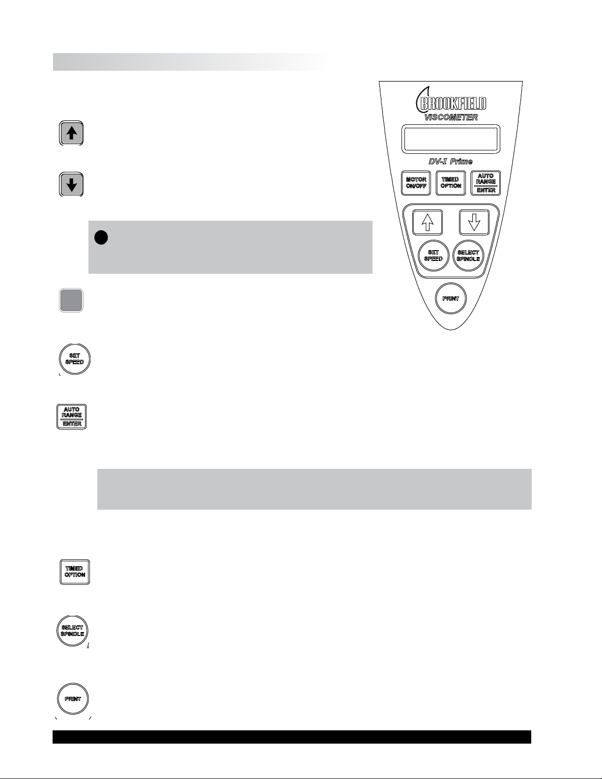
I.7 Key Functions
Figure I-3 shows the control keys on the face of the DV-I PRIME
Viscometer. The following describes each key’s function.
UP ARROW
This key is used to scroll UP (in an increasing value
direction) through the available speed or spindle tables.
DOWN ARROW
This key is used to scroll DOWN (in a decreasing value
direction) through the available speed or spindle tables.
TpNote: Pressing and holding the DOWN ARROW
key during the POWER ON will change the
temperature display between °C and °F.
MOTOR
ON/OFF
MOTOR ON/OFF
Turns the motor ON or OFF.
Figure I-3
Causes the DV-I
SET SPEED
PRIME to begin running at the currently selected speed. Used for Time to
Torque and Timed Stop tests. (see Section II.9 - Timed Modes for Viscosity Measurement.)
AUTO RANGE/ENTER
Auto range presents the maximum (100% torque) viscosity attainable (known as Full Scale
Range) for the spindle/speed selected. This feature is functional when the motor is running.
Viscometer accuracy is 1% of the maximum (100% torque) viscosity value; minimum
recommended viscosity range is 10% of the maximum viscosity value.
Note: Pressing and holding the AUTO RANGE key during power on will enable the
viscosity display to be changed between CGS and SI units (see Section II.5).
ENTER Use to enter parameters in the Timed Stop Mode(see Section II.9.2).
TIMED OPTION
Used to select timed modes for viscosity measurement (see Section II.9), and to select temperature
offset mode (see Section II.9.4).
SELECT SPINDLE
This initiates spindle selection on the rst press and then selects the currently scrolled-to
spindle when pressed a second time. Used for Time to Torque and Timed Stop tests (see
Section II.9 - Timed Modes for Viscosity Measurement).
PRINT
Initiates print modes (see Section II.10.)
Brookeld Engineering Laboratories, Inc. Page 12 Manual No. M/07-022-D0613
Page 13

I.8 Preventative Maintenance and Cleaning
Make sure the instrument is in a decent working environment (dust-free, moderate
temperature, low humidity, etc.)
Make sure the instrument is on a level surface.
Hands/ngers must be clean and free of residual sample. Not doing so may result in
deposit build up on the upper part of the shaft and cause interference between the
shaft and the pivot cup.
Be sure to remove spindle from the instrument prior to cleaning. Note left-hand
thread. Severe instrument damage may result if spindle is cleaned in place.
Instrument and Keypad: Clean with dry, non-abrasive cloth. Do not use solvents or cleaners.
Immersed Components: Spindles and guard leg are made of stainless steel. Clean with
non-abrasive cloth and solvent appropriate for sample material
that is not aggressive to immersed components.
When cleaning, do not apply excessive force, which may result in bending spindles.
Brookeld Engineering Laboratories, Inc. Page 13 Manual No. M/07-022-D0613
Page 14
II. GETTING STARTED
II.1 Auto Zero
Before readings may be taken, the Viscometer must be Autozeroed. This action is performed
each time the power switch is turned on. The display window on the Viscometer will guide you
through the procedure as follows:
NOTE: Check instrument level before proceeding - see Section I.5.
Turn the power switch (located on the rear panel) to the ON position. This will result in the
following screen display:
BROOKFIELD DV-I
PRIME VISCOMETER
Figure II-1
After a few seconds, the following screen appears:
BROOKFIELD DV-I
Instrument Torque
RV V6.0
Firmware Version
Figure II-2
No key press is required at this point. After a short time, the display will clear and the following
will be displayed:
REMOVE SPINDLE
PRESS ANY KEY
Figure II-3
After removing the spindle and pressing a key, the DV -I PRIME begins its Autozero. The screen
will ash “Autozeroing Viscometer”.
AUTOZEROING
VISCOMETER
Figure II-4
NOTE: Be sure that the viscometer is level before initiating Autozero.
Brookeld Engineering Laboratories, Inc. Page 14 Manual No. M/07-022-D0613
Page 15
After approximately 15 seconds, the ashing stops and the following screen appears:
Tp
REPLACE SPINDLE
PRESS ANY KEY
Figure II-5
Pressing a key at this point results in the display of the DV-I PRIME default screen:
Calculated Viscosity
Speed
cP 0.0 S01
OFFRPM % 0.0
Spindle Selected
% Torque
(without Temperature Probe)
Figure II-6a
cP 0.0 70.1°F
Temperature
OFFRPM % 0.0
(with Temperature Probe)
Figure II-6b
The display will vary slightly depending upon the status of the last spindle entry.
II.2 Spindle Selection
LVDV-I PRIME Viscometers are provided with a set of four spindles and a narrow guardleg;
RVDV-I PRIME Viscometers come with a set of six spindles and a wider guardleg; HADV-I
PRIME and HBDV-I PRIME Viscometers come with a set of six spindles and no guardleg (see
Appendix F for more information on the guardleg.)
The spindles are attached to the viscometer by screwing them on to the lower shaft. Note that the
spindles have a left-hand thread. The lower shaft should be held in one hand and lifted up. The
spindles should be screwed to the left. The face of the spindle nut and the matching surface on
the lower shaft should be smooth and clean to prevent eccentric rotation of the spindle. Spindles
can be identied by the number on the side of the spindle nut.
The DV-I PRIME requires a Spindle Entry Code number to calculate viscosity values. The
two-digit entry code for each spindle can be found in Appendix D.
NOTE: The DV-I PRIME will remember the Spindle Entry Code that was in use when the
power was turned off.
II.2.1 Spindle Selection for Models WITHOUT Temperature Display
Pressing the
to blink. It will blink for about three seconds. If the
Brookeld Engineering Laboratories, Inc. Page 15 Manual No. M/07-022-D0613
SELECT SPINDLE key will cause the characters on the top line of the display to begin
UP or DOWN ARROW keys are pressed (while
Page 16
S is blinking) the two character spindle value to the right of the S character will begin to change
Tp
(in either an increasing or decreasing direction depending upon which
each press of the key. If the
spindle codes for as long as the
ARROW key is pressed and held, the display will scroll through the
ARROW key is depressed. When it reaches the last item in the list
(either at the top or bottom of the list) the spindle code displayed will “roll-over” to either the
rst or last spindle code and the scroll action will continue.
ARROW key is pressed) for
When the desired spindle code is displayed, release the
SELECT SPINDLE key once again. This will cause the S character to cease blinking and the new
the
ARROW key to halt further scrolling. Press
spindle code will be accepted for use in viscometer calculations.
NOTE: You have approximately three seconds in which to press the SELECT SPINDLE
key before the blinking stops. If you fail to press the SELECT SPINDLE key
before the blinking stops you will have to repeat the above steps and re-select the
desired spindle.
The DV-I PRIME will begin to calculate using the new spindle parameters as soon as the SELECT
SPINDLE key is pressed the second time.
NOTE: The number 99 spindle is for use with special spindles when using Brookeld’s
WINGATHER32 computer program. Refer to WINGATHER32 operator manual
for further information on using “99” spindles.
DV-I PRIME remembers last spindle selected when power is shut down.
II.2.2 Spindle Section for Models WITH Temperature Display
The steps for selecting and accepting a spindle entry are the same as Section II.2.1 except that
when SELECT SPINDLE is depressed, the temperature display is temporarily replaced by the spindle
entry code until the entry code is accepted (Figure II-7):
cP 123.4 S31
10 RPM % 89.7
Figure II-7
Once the spindle entry code is accepted, the screen will return to the default display:
cP 123.4 70.1°F
10 RPM % 89.7
Figure II-8
Brookeld Engineering Laboratories, Inc. Page 16 Manual No. M/07-022-D0613
Page 17
II.3 Speed Selection & Setting
Table II-1 shows the available speed selections.
DV-I PRIME SPEEDS SETS
Beginning 0.0
When scrolling 0.6
“UP” 1.5
0.3
3.0
6.0
12
30
60
0.0
0.5
1.0
2.0
2.5
4.0
5.0
10
20
50
100
Table II-1
NOTE: DV-I PRIME speeds are organized to conform to the historical speed sets available on
the Brookeld Dial Reading viscometer. Speeds from 0.3-60 RPM are traditionally
found on the LVT viscometer. Speeds from 0.5-100 RPM are traditionally found
on RVT, HAT, and HBT viscometers.
To select a viscometer speed rst press either the UP or DOWN ARROW keys which will cause the
area to the right of RPM (on the bottom line) to display the currently selected speed. Figure II-9
shows the DV-I PRIME had been operating at 10 RPM, and the current selected speed is 10 RPM.
cP 872.0 S01
10RPM10 % 87.2
“Selectable” Speed Operating Speed
Figure II-9
Brookeld Engineering Laboratories, Inc. Page 17 Manual No. M/07-022-D0613
Page 18
If the ARROW key is pressed just once and then released, the characters RPM will blink for three
seconds, then will cease blinking resulting in no change to the speed entry.
NOTE: The speed selection process remembers the last value of scrolled-to speed so that
the next time you initiate a speed change (by pressing an
ARROW key), the DV-I
PRIME will begin its scroll display from the last entered value.
The last scrolled-to-speed does not necessarily have to be the same as the speed at which the
DV-I PRIME is currently running. The user may operate at a given speed and pre-set the DV-I
PRIME to the next desired speed before that speed will be used. For example, if the DV-I PRIME
is currently running at 10 RPM and was previously scrolled to 20 RPM, a single press of either
ARROW key would result in the Figure II-10 screen display:
cP 872.0 S01
10 RPM20 % 87.2
Scrolled to Selected Speed Operating Speed
Figure II-10
Pressing the
If motor is off, pressing the
the last scrolled-to-speed. If you had been running at 10 RPM, pressed
re-started the DV-I PRIME by pressing
SET SPEED key would cause the DV-I PRIME to begin running at 20 RPM.
MOTOR ON/OFF key immediately starts the DV-I PRIME running at
MOTOR ON/OFF and then
MOTOR ON/OFF once again, you would again be running
at 10 RPM. However, if while the motor was off you had scrolled to a new speed of 20 RPM,
pressing the
MOTOR ON/OFF key would start the DV-I PRIME running at 20 RPM.
DV-I PRIME remembers last speed selected when power is shut down.
NOTE: During both spindle or speed selection and scrolling operations, the DV-I PRIME
will continue to calculate and display viscosity (cP) and torque (%).
II.4 Autorange
The AUTO RANGE key allows you to determine the maximum calculated viscosity (full scale reading)
possible with the current spindle/speed setting. Pressing the key at any time will cause the current
viscosity display to change and show that maximum viscosity. The screen torque display will
now display a ashing “%100.0” to indicate this special condition. This maximum viscosity and
ashing %100.0 value will be displayed for as long as the
II-11 shows the
AUTO RANGE function for the situation where the No. 3 RV spindle is rotating at
20 RPM. The Full Scale Range is 5000 cP (or 5000 mPa
AUTO RANGE key is depressed. Figure
.
s).
cP 5000 S03
20 RPM %100.0
Figure II-11
Brookeld Engineering Laboratories, Inc. Page 18 Manual No. M/07-022-D0613
Page 19

NOTE: If the motor is off or the RPM is 0.0, the maximum viscosity displayed will be 0.0
.
cP (or 0.0 mPa
s).
II.5 CGS or SI Units Selection
Pressing and holding the AUTO RANGE key during power on will enable the viscosity display to
be read in either CGS or SI units. To change the unit format:
1. Turn the power off.
2. Press and hold the
AUTO RANGE key and turn the power ON.
The DV-I PRIME will retain the unit selection when the viscometer is turned OFF.
CGS SI
Viscosity cP mPa
•s
II.6 Temperature Display in °F or °C
Pressing and holding the DOWN ARROW key during power on will enable the temperature display
to be read in either degrees Fahrenheit or degrees Centigrade. To change the units format:
1. Turn the power OFF.
2. Press and hold the
DOWN ARROW key and turn power ON.
The DV-I PRIME will retain the unit selection when the viscometer is turned OFF.
Figure II-12 depicts the changes to the default screen when displaying temperature in the Fahrenheit
scale and viscosity display in SI units:
mPas123.4 70.1°F
10 RPM % 89.7
Figure II-12
II.7 Out of Range
Brookeld recommends taking viscosity readings between 10% and 100% of scale. The DV-I
PRIME gives indications for out of specication or out-of-range operation. When % (Torque)
readings exceed 100.0 % (over-range), the display changes to that shown in Figure II-13:
cP EEEE S01
10 RPM % EEEE
Figure II-13
You must change either speed or spindle to correct this condition. If you operate at spindle speeds
that produce % (Torque) below 10.0 % (under-range), the DV -I PRIME ashes both % (Torque)
and cP (Viscosity) on and off:
Brookeld Engineering Laboratories, Inc. Page 19 Manual No. M/07-022-D0613
Page 20

cP 78.0 S01
10 RPM20 % 7.8
Figure II-14
Negative % (Torque) will be displayed as shown in Figure II-15:
cP ---- S01
10 RPM20 % -0.2
Figure II-15
Viscosity values will be displayed as “- - - -” when the % (Torque) is below zero.
II.8 Operation
The following procedure is outlined for making a viscosity measurement in a 600 mL low form
Grifn beaker.
1. Mount the guardleg on the DV-I PRIME Viscometer (LV and RV series). Attach the spindle
to the lower shaft. Lift the shaft slightly, holding it rmly with one hand while screwing
the spindle on with the other (note left-hand thread). Avoid putting side thrust on the shaft.
2. Insert and center spindle in the test material until the uid’s level is at the immersion
groove in the spindle’s shaft. With a disc-type spindle, it is sometimes necessary to tilt
the spindle slightly while immersing to avoid trapping air bubbles on its surface. You
may nd it more convenient to immerse the spindle in this fashion before attaching
it to the Viscometer.
3. To make a viscosity measurement, select the desired speed setting. Allow time for the
indicated reading to stabilize. The time required for stabilization will depend on the
speed at which the Viscometer is running and the characteristics of the sample uid. For
maximum accuracy, readings below 10% should be avoided. Additional information on
making viscosity measurements is available in Appendix C or the Brookeld publication
“More Solutions to Sticky Problems”.
4. Record the reading and relevant test parameters. Brookeld recommends you record both
% torque and viscosity in centipoise. Relevant test parameters might include: viscometer
model, spindle, speed, temperature, container and time of test.
5. Press the
MOTOR ON/OFF key to turn the motor “OFF” when changing a spindle or changing
samples. Remove spindle and guardleg before cleaning. Clean spindles and guardleg after
use, see Section I.8 for general cleaning recommendations.
6. Interpretation of results and the instrument’s use with non-Newtonian and thixotropic
materials is discussed in the booklet, “More Solutions to Sticky Problems”, and in
Appendix C: Variables in Viscosity Measurements.
Brookeld Engineering Laboratories, Inc. Page 20 Manual No. M/07-022-D0613
Page 21

II.9 Timed Modes for Viscosity Measurement
The Timed Modes allow the viscometer user to implement Timed Stop and Time to Torque
capabilities with the DV-I PRIME Viscometer. This feature will allow the user to set up the
viscometer (i.e. select spindle and speed) and then record readings for a xed period of time
(Timed Stop) or until a set torque value is attained (Time to Torque). A series of menus will ask
the user to input minutes and seconds (Timed Stop) or % torque (Time to Torque) and will then
begin timing when the user presses the
MOTOR ON/OFF key to ON. A message will be displayed
showing time remaining (or time elapsed) and the appropriate display item (viscosity or torque)
will be updated continuously during the event. Upon completion, the viscometer will display a
screen stating that the test is complete and will also display the nal recorded value for the viscosity
in the rst case, and the time in minutes and seconds to reach the torque limit in the second case.
II.9.1 Set Up
1. The user must pre-select the display unit option: CGS or SI (see Section II.5).
2. The user then selects (via the
NOTE: If 0.0 RPM is the selected speed setting (the default after executing
3. Next, the user selects the spindle number corresponding to the spindle attached.
4. Now, the user presses the MOTOR ON/OFF key to ensure that the motor is OFF. Setting
the motor to the OFF condition sets up the viscometer for executing the Timed Modes.
5. The user presses the TIMED OPTION key to enter either of the timed test modes. Immediately,
the following screen appears:
The user presses either the
will be ashing.
UP and DOWN arrows) the spindle speed (see Section II.3).
AUTOZERO) the timed modes can be executed; however, the results will
be meaningless showing no viscosity values.
TIMED STOP
TIME TO TORQUE
Figure II-16
UP or DOWN ARROW key to select the test method of choice, which
II.9.2 Timed Stop
1. After pressing the ENTER key when in the display of Figure II-16, the user is presented
with the following screen:
TIMED STOP
SET MIN’S:00
Figure II-17
Brookeld Engineering Laboratories, Inc. Page 21 Manual No. M/07-022-D0613
Page 22

Using the UP and DOWN ARROW keys, the user enters a value for the minutes portion of
the time to stop. This value can be as high as 99 minutes.
2. When satised, the user presses the ENTER key again to enter the seconds setting display:
TIMED STOP
SET SEC’S:00
Figure II-18
Using the
UP and DOWN ARROW keys, the user enters a value for the seconds portion of the time
to stop. This value will be between 0 and 59 seconds.
The user presses the
ENTER key one more time at which point the viscometer will display the
following screen:
TIMED STOP:PRESS
MOTOR ON/OFF
Figure II-19
3. At this point, the user need only press the
MOTOR ON/OFF key to begin the timed stop
operation.
4. We will assume that the user pressed the MOTOR ON/OFF key to ON and is now presented
with the following screen for the duration of the timed run:
CP 123456789
MIN: 15 SEC: 13
Figure II-20
NOTE: When this mode has begun, a press of the MOTOR ON/OFF key will
interrupt the Timed Stop sequence and return the user to normal operation.
The seconds display will decrement from 59 to zero (0) in one (1) second intervals. When
seconds reaches zero (0), the minutes value will decrement by one (1) minute. This will
continue until all of the time has elapsed at which point the viscometer will display the
following screen:
cP 123456789
TIMED STOP DONE
Figure II-21
At this point, the viscometer will stop the motor and continue to display this screen until
the user presses the
UP or DOWN ARROW keys to view the Torque and Speed that were
current at the Timed Stop completion. This display would appear as follows:
Brookeld Engineering Laboratories, Inc. Page 22 Manual No. M/07-022-D0613
Page 23

%=76.4 RPM=100
TIMED STOP DONE
Figure II-22
The display will switch between that of Figures II-21 and II-22 for each press of either the
UP or DOWN ARROW key.
The test can be repeated by pressing the motor ON/OFF key.
Pressing any key except the UP or DOWN ARROW keys or motor ON/OFF will cause the
viscometer to exit the Timed Stop mode and resume normal operation.
NOTE: For the Timed Stop method, the DV-I PRIME Viscometer will retain the last
value for the time interval in MEMORY so that it will become the default
the next time the user elects to use this method.
II.9.3 Time to Torque
1. After pressing the
UP OR DOWN key when in the display of Figure II-16, the user selects
time to torque when ashing and presses enter.
The following screen will be presented:
TIMED TORQUE
SET TORQUE:00%
Figure II-23
Using the
UP and DOWN ARROW keys, the user enters a value for the torque level, which
the viscometer must achieve. This value can be as high as 99%.
2. The user presses the
ENTER key one more time to end the torque input at which point the
viscometer will display the following screen:
TIMED TORQ:PRESS
MOTOR ON/OFF
Figure II-24
3. At this point, the user need only press the
operation.
MOTOR ON/OFF key to begin the timed torque
4. We will assume that the user pressed the
MOTOR ON/OFF key to ON and is now presented
with the following display for the duration of the timed torque run:
Brookeld Engineering Laboratories, Inc. Page 23 Manual No. M/07-022-D0613
Page 24

TORQUE = 24.2%
MIN: 15 SEC:13
Figure II-25
NOTE: When this mode has begun, a press of the MOTOR ON/OFF key will
interrupt the time to torque operation and return the user to normal operation.
The seconds display will increment from zero (0) to 59 in one (1) second intervals and the
current value of the viscometer torque will be updated continuously. When seconds reach
59, the minutes value will increment by one (1) minute. This will continue until the user
selected torque value is attained at which point the viscometer will display the following
screen:
TORQUE = 85.0%
TIMED TORQ DONE
Figure II-26
At this point, the viscometer will stop the motor and continue to display this screen until
the user presses the
UP or DOWN ARROW keys to view the viscosity that was current at the
Timed Torque completion. The display would appear as follows:
22M 54S TO 85%
TIMED TORQ DONE
Figure II-27
CP 123456789
TIMED TORQ DONE
Figure II-28
The display will switch between that of Figures II-27 and II-28
UP or DOWN ARROW key.
for each press of either the
The test can be repeated by pressing the motor ON/OFF key.
Pressing any key except the UP or DOWN ARROW key or motor ON/OFF will cause the
viscometer to exit the Timed Torque mode and resume normal operation.
The time to torque value can be as high as 99 minutes and 59 seconds.
Brookeld Engineering Laboratories, Inc. Page 24 Manual No. M/07-022-D0613
Page 25

NOTE: For the Time to Torque method, the DV-I PRIME Viscometer will retain the
last entered torque in MEMORY for use when the user elects to perform
a time to torque test again.
Tp II.9.4 Temperature Oset
When the optional temperature probe is available with the DV-I PRIME, it is sometimes useful
to be able to adjust the temperature readout to agree with an external temperature device. This
can be accomplished utilizing the Temp Offset mode.
1. Enter the Timed Options menu by pressing the TIMED OPTION key. Use the up or
down arrow key to select Temp Offset. The following screen will be presented.
TEMP OFFSET
TIMED STOP
Figure II-29
2. Press ENTER. Figure II-30 will appear.
SET TEMP OFFSET?
NO $# THEN ENTER
Figure II-30
3. Press the UP/DOWN keys for YES or NO.
4. If NO is entered, temperature offset is disabled and display will return to default screen.
5. If YES is entered, the screen in Figure II-31 appears.
ENTER TEMP
$# +0.0 OFFSET
Figure II-31
6. Use UP/DOWN arrows to scroll from +5.0 to -5.0 degrees C offset in 0.1º increments.
(When temperature units are set to Fahrenheit, offset range is -9.0 to +9.0 degrees F)
7. Press ENTER to choose Temp Offset. The offset will be conrmed by the following
screen, which will be displayed for 5 seconds, then returns to default screen.
TEMP OFFSET ENABLED
Figure II-32
Brookeld Engineering Laboratories, Inc. Page 25 Manual No. M/07-022-D0613
Page 26

When Temp Offset is enabled the temperature units display will be underlined.
08
08
08
08
Cp 0.0 70.1°F
0.0 RPM % 0.0
Figure II-33
NOTE: Temp. offset remains active when unit is powered down and powered up again.
II.10 Print Modes
NOTE: The print key is inactive when the motor is off. The printer must be attached to
the appropriate rear panel output connector. See Appendix G.
1. Press the print key once (less than 3 seconds) and DV-I PRIME will print one standard
line to a printer through the serial port output.
Figure II-34 shows examples of the print strings for CGS and SI units.
For the case of CGS units with non-exponential results:
11020304050607
RPM=XXX M=XXXXX S=XX %=XXX.X cP=XXXXX D/CM2=XXXXX 1/SEC=XXXXX T=XX.XC ZXX:XX
and CGS units with exponential results.
11020304050607
RPM=XXX M=XXXXX S=XX %=XXX.X cP=XXXeX D/CM2=XXXeX 1/SEC=XXXXX T=XX.XC ZXX:XX
Similarly, for SI units with non-exponential results.
11020304050607
RPM=XXX M=XXXXX S=XX %=XXX.X mPas=XXXXX N/M2=XXXXX 1/SEC=XXXXX T=XX.XC ZXX:XX
and SI units with exponential results.
11020304050607
RPM=XXX M=XXXXX S=XX %=XXX.X mPas=XXXeX N/M2=XXXeX 1/SEC=XXXXX T=XX.XC ZXX:XX
M = Torque T = Temperature Z = Time
Figure II-34
2. T o initiate a continuous print mode, press and hold the print key for more than 3 seconds
and the following screen appears.
0
0
0
0
Brookeld Engineering Laboratories, Inc. Page 26 Manual No. M/07-022-D0613
Page 27

PRINT INTERVAL
SET MIN’S: 00
Figure II-35
3. Use up and down arrows to enter desired minutes for print interval (00 to 99).
4. Press enter to accept minute value and advance to set sec (00 to 59).
PRINT INTERVAL
SET SEC’S: 00
Figure II-36
5. Press enter and the instrument will start to print at the interval, which has been set.
The instrument display will show a ashing P in front of the % sign when operating in
continuous print mode.
CP123.4 S01
10RPM P% 19.7
Figure II-37
6. To pause printing, turn motor off.
7. To stop continuous print mode, press print key.
II.11 Communication with Wingather Software
The DV-I PRIME can be used in conjunction with the Brookeld software program Wingather.
Wingather will collect the data output from the DV-I PRIME and allow for; data storage, data
printing, graphing, and mathematical analysis.
NOTE: Wingather must be version 3.0 or higher for use with DV-I PRIME.
The DV-I Prime must be set to continuous print mode for proper communication to Wingather
(Refer to Section II.10 for instruction). Set the print interval to 00MIN and 01SEC. Data collection
modes are detailed in the Wingather Help les. All test controls will remain at the DV-I PRIME
(spindle selection, speed selection, speed change). The communication cable (part number DVP-
80) for connecting the DV-I PRIME to the computer is supplied with the Wingather software.
Important features and benets in Wingather, which enhance operator versatility in performing
viscosity tests, include the following:
• 32-bit operation for rapid performance.
• Wingather version 3.0 is compatible with Windows™ 2000, NT, XP, Vista, and Windows™
7 operating systems for exible operation.
Brookeld Engineering Laboratories, Inc. Page 27 Manual No. M/07-022-D0613
Page 28

• Brookeld’s DV Loader software (for setting up test programs) is integrated into WINGATHER.
DV Loader is an easy-to-use, structured command language, which makes detailed viscosity
tests simple to program (see Section V).
• Easy-to-use data gather modes including automatic follow up events (save data, analyze
data, print data).
• Manual scaling of plot axes.
• Auto range feature which shows in screen display the complete viscosity range which can
be measured at any shear rate for a specic spindle geometry.
• Concurrent plotting of six data sets on one graph.
The following gures show the principal screens associated with Wingather:
Figure II-38: Dashboard Screen
Brookeld Engineering Laboratories, Inc. Page 28 Manual No. M/07-022-D0613
Page 29

Figure II-39: Gather Screen
Figure II-40: DV Loader Screen
Brookeld Engineering Laboratories, Inc. Page 29 Manual No. M/07-022-D0613
Page 30

Figure II-41: Run/Data Screen
Figure II-42: Analysis Screen
Brookeld Engineering Laboratories, Inc. Page 30 Manual No. M/07-022-D0613
Page 31

II.12 Math Models
t
Math models provide parameters that indicate how materials will behave in various circumstances
where shear stress and shear rate vary. The data and calculated model parameters can be used
to help QC and R&D characterize how a product will behave for the customer and how it will
behave during processing.
When selecting a math model, it is important to take into consideration the parameters that need
to be measured, as well as, the condence of t (CoF). A CoF above 98 is recommended. This
appendix discusses the parameters of the following four models, what kinds of materials they
should be used with, and provides an example of each. All models discussed are available with
Brookeld’s Rheocalc™, Wingather™, and RHEO 3000™ software.
• Power Law (Ostwald)
• Herschel-Bulkley
• Bingham
• Casson
In addition to the above models, this section also briey covers the NCA/CMA Casson model
and the IPC Paste Model. These can be found at the end of this section.
II.12.1 The Power Law (Ostwald) Model
(
= shear stress, k = consistency index, = shear rate, and n = ow index)
What does it tell you?
The Power Law model provides a consistency index, k, which is a product’s viscosity at one
reciprocal second. (Reciprocal seconds are the units of measurement for shear rate.) It also
provides a ow index, n, which indicates the degree with which a material exhibits non-Newtonian
ow behavior. Since Newtonian materials have linear shear stress vs. shear rate behavior and
n describes the degree of non-Newtonian flow, the flow index essentially indicates how
“non-linear” a material is.
Figure II-43
Brookeld Engineering Laboratories, Inc. Page 31 Manual No. M/07-022-D0613
Page 32

When n < 1 the product is shear-thinning or Pseudoplastic. This means the apparent viscosity
t
t
o
t
o
t
o
decreases as shear rate increases. The closer n is to 0, the more shear thinning the material is.
When n > 1 the product is shear-thickening or Dilatant. Their apparent viscosity increases as
shear rate increases.
When should you use it?
This model should be used with non-Newtonian, time-independent uids that do not have a yield
stress. These uids will begin to ow under any amount of shear stress. Graphs of such material
generally intersect the y-axis at 0.
An Example of the Power Law Model at Work
Formulators at a personal care company
would like to use a substitute ingredient to
Shampoo
decrease cost. They use the Power Law model
to evaluate the eect the new ingredient
will have on the behavior of their shampoo.
Flow Index (n) = 0.08
Consistency Index (k) = 91071cP
They need to know how it will behave during
processing and how it will behave when it is
being used be the consumer
With the new ingredient the shampoo has a ow index (n) of 0.08. This indicates that the
shampoo is shear-thinning enough to ow properly during processing and that it will ow
properly for the end-user. The consistency index, k, indicates how the shampoo behaves
when it experiences low shear rates. The power law values show that the shampoo
becomes quite thin at process shear rates and therefore it can be easily pumped into lling
equipment, hold tanks, etc. The consistency index of 91,071 cP shows that the shampoo
is very viscous at low shear rates, and as a result, it will appear to customers to be “rich and
creamy” while still being easy to apply.
II.12.2 The Herschel-Bulkley Model
(
= shear stress,
= yield stress, k = consistency index, = shear rate, and n = ow index)
What does it tell you?
The Herschel-Bulkley model is simply the Power Law model with the addition of
stress. Yield stress,
, denotes how much shear stress is required to initiate ow. This model also
for yield
provides a consistency index, k, which is a product’s viscosity at 1 reciprocal second, and a ow
index, n, which indicates the degree with which a material exhibits non-Newtonian ow behavior.
Since Newtonian materials have linear shear stress vs. shear rate behavior and n describes the
degree of non-Newtonian ow, the ow index essentially indicates how “non-linear” a material
is. For Herschel-Bulkley uids, n will always be greater than or less than 1.
When n < 1 the product is shear-thinning or Pseudoplastic. This means the apparent viscosity
decreases as shear rate increases. The closer n is to 0, the more shear thinning the material is.
Brookeld Engineering Laboratories, Inc. Page 32 Manual No. M/07-022-D0613
Page 33

When n > 1 the product is shear-thickening or Dilatant. It’s apparent viscosity increases as shear
t
o
rate increases.
Figure II-44
When should you use it?
The Herschel-Bulkley model should be used with non-Newtonian, time-dependent materials that
have a yield stress. Products with a yield stress only begin to ow after a certain amount of shear
stress is applied. As a result, the ow curve intersects the y-axis at a point greater than 0. After
yielding, the product creates a ow curve and behaves as a Power Law uid so that n indicates
where there is a shear-thinning or shear-thickening tendency. (In this case, if n =1, the material
is behaving as a Bingham uid, which is discussed next.)
An Example of the Herschel-Bulkley Model at Work
A company uses a gel-like substance as part
of their production process. Upon arrival
they test the material and apply the HerschelBulkley model to ensure it will perform
correctly during process. The results in Figure
II-44 show that the consistency index is 8,550
Gel-Like Substance
n = 0.66
= 51.0 dynes/cm
k = 8550 cP
2
cP, the ow index is 0.66, and the yield stress
is 51.0 dynes/cm2. These results indicate that
this batch of gel does not quite meet specication. While the consistency index is within
spec, the yield value is higher than normal so the uid will not begin to ow as easily. With
a ow index of 0.66, this batch is also less shear thinning than normal. Pump and mixer
speeds must be adjusted before using this material.
Brookeld Engineering Laboratories, Inc. Page 33 Manual No. M/07-022-D0613
Page 34

II.12.3 The Bingham Model
t =
t
o
hD
t
t
o
t
o
t
o
(
+
= shear stress,
What does it tell you?
= yield stress, h = plastic viscosity, and D = shear rate)
The Bingham model indicates a product’s yield stress,
, which is the amount of shear stress
required to initiate ow. It also provides the plastic viscosity,
product yields.
h, which is the viscosity after a
Figure II-45
When should you use it?
This model should be used with non-Newtonian materials that have a yield stress and then behave
in a Newtonian fashion once they begin to ow. As a result, the shear stress-shear rate plot forms
a straight line after yielding. (Products that have a yield stress only begin to ow after a certain
amount of shear stress is applied. They are also called “viscoplastic”. Their shear stress vs. shear
rate graphs intersect the y-axis at a point greater than 0.)
An Example of the Bingham Model at Work
A manufacturer of drilling uid applies the
Bingham Model to ensure the quality of their
Drilling Fluid
product. Results from a recent batch, shown
in Figure II-45, showed that the yield stress
and plastic viscosity were both below the
Plastic Viscosity (
Yield Stress (
h) = 6621 cP
) = 166.4 dynes/cm
2
pass/fail criteria, which would cause the uid
to insuciently hold-up the cuttings. The
shipment was cancelled and the root-cause
of the problem was identied.
Brookeld Engineering Laboratories, Inc. Page 34 Manual No. M/07-022-D0613
Page 35

II.12.4 The Casson Model
D
t
t
o
t
o
t
o
t = to+ h
= shear stress,
= yield stress, h = plastic viscosity, and D = shear rate)
(
What does it tell you?
The Casson model provides parameters similar to that of the Bingham model. However, unlike
the Bingham model, it was developed for materials that exhibit non-Newtonian ow after yielding.
The Casson model indicates the product’s yield stress (
required to initiate ow, and the product’s plastic viscosity,
), which is the amount of shear stress
h, which is the viscosity of the product
after it yields.
Figure II-46
When should you use it?
The Casson model should be used with non-Newtonian materials that have a yield stress and that
do not exhibit a “Newtonian-like” behavior once they begin to ow. This model is most suitable
for uids that exhibit Pseudoplastic or shear thinning, ow behavior after yielding.
These uids have a non-linear ow curve. The point at which it crosses the y-axis is the product’s
yield stress (
). To protect the point at which the curve will intersect with the y-axis, the Casson
model linearizes or straightens the plot by taking the square root of the data. To ensure accurate
extrapolation to yield stress it is best to take some data at low shear rates.
Brookeld Engineering Laboratories, Inc. Page 35 Manual No. M/07-022-D0613
Page 36

An Example of the Casson Model at Work
t
o
t
o
Before releasing a new over the counter gel, a
pharmaceutical company needs to learn how
it will behave which it is being used by the
end consumer. They perform a full viscosity
prole and apply the Casson model. From the
Pharmaceutical Gel
Plastic Viscosity (
Yield Stress (
h) = 329.8 cP
) = 325.8 dynes/cm
2
results, shown in Figure II-46, they learn that
their ointment has a higher yield stress,
lower plastic viscosity,
h, than they originally
, and
intended. As a result it is difcult or dispense from its container (due to the high yield stress)
and it does not hold it shape very well (due to the low plastic viscosity), making it difcult to
apply a small amount to the affected area of the skin. Based on this data, formulators are able
to modify the ingredients accordingly. Once a formulation is established, multi-point tests and
the Casson model are performed as a QC tool to check batches before and after processing.
Brookeld Engineering Laboratories, Inc. Page 36 Manual No. M/07-022-D0613
Page 37

II.12.5 Other Common Rheological Models
t
2 t
+
hg
t
t
o
The NCA/CMA Casson Model
(1 + a)
=
o
(1 + a)
(
= shear stress
,
= yield stress, h = plastic viscosity, and = shear rate)
The NCA/CMA Casson model is designed by the National Confectioners Association and the
Chocolate Manufacturers Association as the standard rheological model for the industry. This
model determines yield and ow properties under specied conditions and closely approximates
the plastic behavior of chocolate before nal processing.
Figure II-47
When chocolate is used for enrobing, it must have a yield stress high enough to stay in place once
it enrobes the lling. In the case of decorating chocolate, the yield stress must be high enough so it
can keep its shape once it has been squeezed into place through a nozzle. For molding chocolate,
the plastic viscosity must be low enough to completely ll the mold.
(The NCA/CMA lists Brookeld’s HA-spring range viscometer with a Small Sample Adapter,
SC4-27 spindle and SC4-13R sample chamber as the approved apparatus.)
The IPC Paste Model
n
h=kR
(h = viscosity, k = consistency index, R = rotational speed, n = shear sensitivity factor)
The IPC Paste Model was developed for solder pastes. It calculates the viscosity of solder pastes
at 10rpm. The IPC Paste Model requires that the product be tested with a Brookeld Spiral
Adapter at multiple speeds. More details can be found in the IPC-TM-650 Test Methods Manual
(methods 2.4.34.2 and 2.4.3).
Brookeld Engineering Laboratories, Inc. Page 37 Manual No. M/07-022-D0613
Page 38

This model is a variation of the Power Law Model. Unlike the Power Law Model, which relates
apparent viscosity to shear rate, the IPC Paste Model relates apparent viscosity to the testing
speed (rpm).
Figure II-48
Figure II-49
Brookeld Engineering Laboratories, Inc. Page 38 Manual No. M/07-022-D0613
Page 39

III. MAKING VISCOSITY MEASUREMENTS
III.1 Quick Start
Viscosity Measurement
The DV-I PRIME Viscometer uses the same methodology for viscosity measurement as the
Brookeld Dial Reading Viscometer and DV series of Digital Viscometers. If you have experience
with other Brookeld equipment, this section will give you the quick steps for taking a viscosity
reading. If you have not used a Brookeld Viscometer before, skip this section and go to Section
III.2 for a detailed description.
A) Assemble and level the viscometer (Section I.5).
B) Autozero the viscometer (Section II.1).
C) Enter the spindle number using the SELECT SPINDLE key (Section II.2).
D) Introduce the spindle into the sample and attach the spindle to the coupling nut.
NOTE: Left-hand threads.
E) Enter the speed of rotation using the ARROW KEYS and SET SPEED key (Section II.3).
F) Record % torque and viscosity.
III.2 Preparations for Making Measurements
A) VISCOMETER: The DV-I PRIME should be turned on, leveled and autozeroed. The
level is adjusted using the two feet on the bottom of the base and conrmed using the
bubble on the top of the head. Adjust the feet until bubble is inside the center target. Set
the level prior to autozero and check the level prior to each measurement.
Proper level is essential for correct operation of the DV-I PRIME.
B) SAMPLE: The uid to be measured (sample) must be in a container. The standard spindles,
supplied with the DV-I PRIME (LV (1-4), RV (2-7), or HA/HB (2-7)), are designed to be
used with a 600 mL low form Grifn beaker (or equivalent container with a diameter of
8.25cm). The same applies to the optional RV1, HA/HB1. Many other spindle systems
are supplied from Brookeld with specic sample chambers such as the Small Sample
Adapter, UL Adapter and Thermosel.
Brookeld recommends that you use the appropriate container for the selected spindle.
You may choose to use an alternate container for convenience; however, this may have an
effect on the measured viscosity. The DV-I PRIME is calibrated considering the specied
container. Alternate containers will provide results that are repeatable but not “true.”
The LV (1-4) and RV (1-7) spindles are designed to be used with the guardleg attached.
Measurements made without the guardleg will provide repeatable results but may not
provide “true” results.
Brookeld Engineering Laboratories, Inc. Page 39 Manual No. M/07-022-D0613
Page 40

When comparing data with others, be sure to specify the sample container and
presence/absence of the guardleg.
Many samples must be controlled to a specic temperature for viscosity measurement.
When conditioning a sample for temperature, be sure to temperature control the container
and spindle as well as the sample.
Please see our publication, “More Solutions to Sticky Problems”, for more details relating
to sample preparation.
III.3 Selecting a Spindle/Speed
The DV-I PRIME has the capability of measuring viscosity over a wide range (for example, the
RVDV-I PRIME can measure uids within the range of 100-13,000,000 cP) (see Appendix B).
This range is achieved through the use of several spindles over many speeds.
The process of selecting a spindle and speed for an unknown uid is normally trial and error. An
appropriate selection will result in measurements made between 10-100 on the instrument
% torque scale. Two general rules will help in the trial and error process.
1. Viscosity range is inversely proportional to the size of the spindle.
2. Viscosity range is inversely proportional to the rotational speed.
In other words: to measure high viscosity, choose a small spindle and/or a slow speed. If the
chosen spindle/speed results in a reading above 100%, then reduce the speed or choose a smaller
spindle.
Experimentation may reveal that several spindle/speed combinations will produce satisfactory
results between 10-100%. When this circumstance occurs, any of the spindles may be selected.
Non-Newtonian uid behavior can result in the measured viscosity changing if the spindle and/
or speed is changed. See our publication, “More Solutions to Sticky Problems,” for more detail.
When viscosity data must be compared, be sure to use the same test methodology: the same
instrument, spindle, speed, container, temperature and test time.
III.4 Multiple Data Points
The majority of viscosity measurements are made at the quality control level and often consist
of a single data point. The test is conducted with one spindle at one speed. The data point is a
useful benchmark for the go/no-go decision in a production setting. The DV-I PRIME can be
used for single point measurement.
Many uids exhibit a characteristic change in viscosity and yield stress with a change in applied
force. This non-Newtonian ow behavior is commonly seen in paints, coatings and food products
as a decrease in viscosity as shear rate increases or an increase in yield stress as rotational speed
Brookeld Engineering Laboratories, Inc. Page 40 Manual No. M/07-022-D0613
Page 41

increases. This behavior cannot be detected or evaluated with the single point measurement.
Non-Newtonian ow is analyzed through the collection of viscosity data over a range of shear rates
and the generation of a graph of viscosity versus shear rate (a rheogram). This information will
allow for a more complete characterization of a uid and may help in formulating and production
of the product. The DV-I PRIME is capable of collecting multiple data points for comprehensive
analysis of ow behavior. Wingather Software can be used for this type of analysis.
More information on ow behavior, shear rate and rheograms is available in our publication,
“More Solutions to Sticky Problems.”
Brookeld Engineering Laboratories, Inc. Page 41 Manual No. M/07-022-D0613
Page 42

Appendix A - Cone/Plate Viscometer Set-Up
Pilot Light
(red)
Toggle Swtich
Contact Light
(yellow)
Sliding Reference
Marker
Micrometer
Adjustment Ring
This Cone/Plate version of the DV-I PRIME uses the same operating instruction procedures as
described in this manual. However, the “gap” between the cone and the plate must be veried/
adjusted before measurements are made. This is done by moving the plate (built into the sample
cup) up towards the cone until the pin in the center of the cone touches the surface of the plate,
and then by separating (lowering) the plate 0.0005 inch (0.013mm).
DV-I PRIME Cone/Plate Viscometers have an Electronic Gap Setting feature. This feature
enables the user to easily nd the 0.0005 inch gap setting that was established at Brookeld prior
to shipment.
The following information explains how to set the Electronic Gap and verify calibration of the
DV-I PRIME Viscometer.
A.1 Electronic Gap Setting Features
TOGGLE SWITCH allows you to enable/disable the Electronic Gap Setting Feature: left position is
OFF (disabled), right position is ON (enabled).
PILOT LIGHT is the red (LED) light; when illuminated, it means the Electronic Setting Function is
sensing (enabled).
CONTACT LIGHT is the yellow (LED) light; when it rst turns on, the “hit point” has been found.
SLIDING REFERENCE MARKER is used after nding the “hit point;” it is the reference for establishing
the 0.0005 inch gap.
MICROMETER ADJUSTMENT RING is used to move the cup up or down in relation to the cone spindle.
Turning the ring left (clockwise) lowers the cup; turning it right (counterclockwise) raises the cup.
Each line on the ring represents one scale division and is equivalent to 0.0005 inch movement of
the plate relative to the cone.
Brookeld Engineering Laboratories, Inc. Page 42 Manual No. M/07-022-D0613
Figure A-1
Page 43

A.2 Setup
Spindle
Wrench
(CPE) Cone
These surfaces
must be clean!
Coupling Nut
Micrometer
Adjustment
Ring
Do Not hit the
CONE with the CUP!
Sample
Cup
(CPE-44Y
or
CPE-44PY)
Bath/Circulator
Bath
Inlet
Bath
Outlet
Cup
Outlet
Cup
Inlet
Micrometer
Ring
1. Be sure that the Viscometer is securely mounted
to the Laboratory Stand, leveled and zeroed
with no cone or cup attached and 0% torque
is displayed.
2. Figure A-2 shows a typical water bath setup.
Connect the sample cup inlet/outlet ports to
the water bath inlet and outlet and set the
bath to the desired test temperature. Allow
sufcient time for the bath to reach the test
temperature. The temperature range of the
Sample Cup (CPE-44Y or CPE-44PY) is
0-100°C. Brookeld recommends a maximum
temperature of 80°C to allow for direct hand
contact for adjustment of the micrometer ring.
When using the sample cup at temperatures
near 0°C, be careful to avoid frost buildup on
the top surface of the cup; this could prevent a
proper t with the micrometer ring. Please refer
to the bath manual for the proper selection of
bath uid and tubing to ensure safe and proper
operation.
Figure A-2
3. The Viscometer has been supplied with a special
cone spindle(s), which contains the Electronic
Gap Setting feature. The “CPE” part number
designation on the cone veries the Electronic
Gap Setting feature.
4. With the motor off, thread the cone spindle
by using the spindle wrench to secure the
viscometer coupling nut (see Figure A-3);
gently push up on the coupling nut and hold
this securely with the wrench. Thread the cone
spindle by hand. Note: Left Hand Threads.
5. Attach the cup, taking care not to hit the cone
with the cup (Figur e A-4). There must be no
uid in the cup.
6. Option: The sample cup is available with an
optional purge tting. The user can connect
a dry gas line to this and put a blanket of dry
gas over the sample during measurement, if
desired.
Figure A-3
Brookeld Engineering Laboratories, Inc. Page 43 Manual No. M/07-022-D0613
Figure A-4
Page 44

A.3 Setting the Gap
Moves Away
from Hit Point
(clockwise)
LEFTx
Moves Towards
Hit Point
(counter-clockwise)
RIGHT
1.
Move the toggle switch to the right; this will
turn on (enable) the Gap Setting Feature. The
Pilot (red) light will be illuminated.
2. If the contact light (yellow) is illuminated, turn
the micrometer adjustment ring clockwise (as
you look down on the instrument) until the
light is just breaking contact, i.e., ickering
(see Figure A-5).
3. If the yellow contact light is not illuminated,
slowly turn the micrometer adjustment ring in
small increments (one or two scale divisions)
counter-clockwise.
Continue moving the micrometer adjustment ring slowly
Figure A-5
counter-clockwise until the contact light
(yellow) turns on. Back off (rotate clockwise)
until the light is just breaking contact, i.e.,
ickering.
4. Adjust the sliding reference marker, right or
left, to the closest full scale division mark (see
Figure A-6).
5. Turn the micrometer adjustment ring one scale
division to the left to meet the line on the
sliding reference marker. THE YELLOW
CONTACT LIGHT SHOULD GO OFF.
6. You have established the gap space needed for
measurement. NOW TURN THE TOGGLE
SWITCH OFF (LEFT); THE RED PILOT
LIGHT SHOULD GO OFF.
This viscoity of “electrically conductive”
uids may be affected if readings are taken
with the Electronic Gap Setting feature
“on”. Be sure to shut the feature “off”
before taken readings!
7. Carefully remove the sample cup.
Notes:
1. The cup may be removed and replaced without resetting the gap, if the micrometer
adjustment ring has not been moved.
2. Remove the spindle from the viscometer when cleaning.
3. Re-establish the hit point every time the spindle is attached/detached.
Figure A-6
Brookeld Engineering Laboratories, Inc. Page 44 Manual No. M/07-022-D0613
Page 45

A.4 Making Measurements with Cone/Plate Geometry
Viscosity measurements are made on the DV-I PRIME C/P viscometer in the same way as the
DV-I PRIME viscometer with several exceptions.
1. Prepare the viscometer as is described in Section III.2.
2. Brookeld recommends that you always make cone/plate measurements with temperature
control. Be sure that the sample cup is connected to a circulating waterbath and that it
is at the target temperature. If the set temperature is far from ambient, you may wish to
preheat the spindle as well as the cup. The spindle can be preheated by removing it from
the viscometer and resting it in the cup (be careful not to scratch the measurement surfaces
on the spindle or cup). Attach the spindle to the viscometer prior to the next step.
3. Set the Gap (see Appendix A; Section A.3) Brookeld recommends that the gap be set at
the same temperature at which the measurement will be made.
4. Remove the sample cup.
5. Measure the precise volume of sample required for the spindle. See Table A-1. Sample
volume can have a great affect on the measurement. In general it is better to over ll the
gap slightly than it is to under ll. It is also benecial to establish a method of sampling
that is repeatable to contribute to the repeatability of your viscosity measurement.
6. Insert the sample into the center of the sample cup. Avoid air bubbles when possible.
7. Attach the sample cup to the viscometer (be careful not to tilt the sample cup as this would
reposition the sample from the center).
8. Wait for thermal equilibrium. Brookeld recommends a minimum of 1 minute for thermal
equilibrium. You may want to increase this time if; there is a large difference in temperature
between the sample and the control point, or if you have not preheated the spindle.
9. Operate the viscometer (see Section II.8, Steps 3 – 6). Refer to Section III.3 for assistance
in selecting a spindle or speed.
10. Remove the sample cup at the conclusion of the test. Be careful to lower the cup so that
no contact is made between the cup and spindle.
11. Remove the spindles (Refer to Appendix A; Section A.2, Step 4).
Cleaning: Refer to Section I.8 for general cleaning recommendations. Clean the cup and spindle
at the conclusion of each test. Be careful not to let the sample dry or harden onto the spindle or
cup since mechanical scraping may damage the measurement surfaces. Brookeld recommends
that you remove the spindle prior to cleaning.
Take care not to scratch the measurement surface of the cup or spindle during the cleaning
process. Take care not to drop the spindle; any dent on the outer edge of the spindle will
affect the measurement.
The sample cup may be provided with an embedded temperature probe. The temperature probe
connection should not be exposed to the cleaning solution or the test sample. Do not immerse
the sample cup in a cleaning solution.
Brookeld Engineering Laboratories, Inc. Page 45 Manual No. M/07-022-D0613
Page 46

A.5 Verifying Calibration
1. Determine the appropriate sample volume. Refer to Table A-1 to determine the correct sample
volume required for the spindle to be utilized.
2. Select a Brookeld Viscosity Standard uid that will give viscosity readings between 10% and
100% of Full Scale Range. Refer to Appendix B for viscosity ranges of cone spindles; ranges
listed apply to CPE cones.
Do not use a silicone viscosity standard uid with a viscosity value greater than 5000 cP with a
Cone/Plate. Brookeld offers a complete range of mineral oil viscosity standards suitable for
-1
use with Cone/Plates for viscosities above 5,000 cP or shear rates above 500 sec
; see Table E-1
and E-2 in Appendix E for a list of available uids.
It is best to use a viscosity standard uid that will be close to the maximum viscosity for a given
cone spindle/speed combination.
Example: LVDV-I PRIME Viscometer, Cone Spindle CPE-42, Brookeld Silicone
Viscosity Standard having a viscosity of 9.7 cP at 25°C.
At 60 RPM, the Full Scale Viscosity Range is 10.0 cP. Thus, the viscometer reading should be
97% torque and 9.7 cP viscosity ± 0.197 (closer to ±0.2) cP. The accuracy is a combination of
viscometer and uid tolerance (refer to Interpretation of Calibration Test Results at the end
of Appendix E).
3. With the motor off, remove the sample cup and place the viscosity standard uid into the cup.
Cone Part No.
CPE-40
CPE-41
CPE-42
CPE-51
CPE-52
Sample Volume
0.5 mL
2.0 mL
1.0 mL
0.5 mL
0.5 mL
Table A-1
4. Attach the sample cup to the viscometer and allow sufcient time for the sample, cup and cone
to reach temperature equilibrium.
5. Turn the motor on. Set the desired speed(s). Measure the viscosity and record the reading in
both % torque and centipoise (cP).
NOTE: The cone spindle must rotate at least ve (5) times before a viscosity reading is
taken.
6. Verify that the viscosity reading is within the allowable 1% deviation, as explained earlier, for
the specic viscosity standard uid(s) that you are using.
* The CPE designation on the cone spindle indicates use with Electronic Gap Setting Cone/Plate
Viscometers/Rheometers only.
Brookeld Engineering Laboratories, Inc. Page 46 Manual No. M/07-022-D0613
Page 47
Appendix B - Viscosity Ranges
LV (#1-4) and RV,HA,HB (#1-7) Viscometers
Viscosity Range (cP)
Viscometer
LVDV-1 PRIME
RVDV-I PRIME
HADV-I PRIME
HBDV-I PRIME
*Minimum viscosity is achieved with
optional RV/HA/HB-1 spindle. (Spindle Code 01)
Vane Spindles
Minimum Maximum
15 2,000,000
100* 13,300,000
200* 26,600,000
800* 106,400,000
Spindle
V-71
V-72
V-73
V-74
V-75
V-71
V-72
V-73
V-74
V-75
V-71
V-72
V-73
V-74
V-75
V-71
V-72
V-73
V-74
V-75
Torque
Range
LV NOT RECOMMENDED FOR USE ON LV TORQUE
LV
LV
LV
LV
RV
RV
RV
RV
RV
HA
HA
HA
HA
HA
HB
HB
HB
HB
HB
Shear Stress Range
Pa dyne/cm
.188-1.88 1.88-18.8
.938-9.38 9.38-93.8
9.38-93.8 93.8-938
3.75-37.5 37.5-375
.5-5 5-50
2-20 20-200
10-100 100-1000
100-1000 1000-10000
40-400 400-4000
1-10 10-100
4-40 40-400
20-200 200-2000
200-2000 2000-20000
80-800 800-8000
4-40 40-400
16-160 160-1600
80-800 800-8000
800-8000 8000-80000
320-3200 3200-32000
2
Viscosity Range cP (mPa•s)
199 - 1990
996 - 9960
4990 - 49900
1996 - 19960
262 - 2620
1110 - 11100
5350 - 53500
54300 - 543000
21300 - 213000
524 - 5240
2220 - 22200
10700 - 107000
108600 - 1086000
42600 - 426000
2096 - 20960
8880 - 88800
42800 - 428000
434400 - 4344000
170400 - 1704000
@ 10 rpm
Notes: 1) 1 Pa = 10 dyne/cm
2
2)1cP=1mPa•s
3) Possibility of turbulence at speeds above 10 rpm may give artificially higher viscosity read ings.
Brookeld Engineering Laboratories, Inc. Page 47 Manual No. M/07-022-D0613
Page 48

Small Sample Adapter and Thermosel
SSA and
Thermosel
Spindle
SC4-16
SV4-18
SC4-25
SC4-31
SC4-34
SC4-81
SC4-82
SC4-83
SSA and
Thermosel
Spindle
SC4-14 1,250 - 4,165,000 2,500 - 8,330,000 10,000 - 33,360,000 .40N
SC4-15 500 - 1,660,000 1,000 - 3,320,000 4,000 - 13,280,000 .48N
SC4-25 0 - 167,000 100 - 334,000 400 - 1,336,000 .93N
SC4-27 250 - 830,000 500 - 1,660,000 2,000 - 6,640,000 .34N
SC4-28 500 - 1,660,000 1,000 - 3,320,000 4,000 - 3,280,000 .28N
SC4-29 1,000 - 3,330,000 2,000 - 6,660,000 8,000 - 26,640,000 .25N
Thermosel
SC4-81
SSA
SC4-82
SSA
SC4-83
RVDV-1 PRIME HADV-I PRIME HBDV-I PRIME
37 - 10,000 73.0 - 10,000 292 - 10,000 1.29N
37 - 10,000 73.0 - 10,000 292 - 10,000 1.29N
121 - 50,000 243 - 50,000 970 - 50,000 1.29N
Viscosity Range (cP)
LVDV-1 PRIME
120 - 400,000 .29N
3 - 10,000 1.32N
480 - 1,600,000 .22N
30 - 100,000 .34N
60 - 200,000 .28N
3 - 10,000 1.29N
3 - 10,000 1.29N
11 - 38,000 1.29N
Viscosity (cP) Shear Rate
Shear Rate sec-1
sec-1
UL Adapter
UL Spindle
YULA-15 or 15Z 1 - 2,000 7 - 2,000 13 - 2,000 52 - 2,000 1.22N
ULA-DIN-Y 1 - 3,800 11 - 5,000 22 - 5,000 85 - 2000 1.29N
Brookeld Engineering Laboratories, Inc. Page 48 Manual No. M/07-022-D0613
LVDV-I PRIME RVDV-I PRIME HADV-I PRIME HBDV-I PRIME
Viscosity (cP)
Shear Rate
sec-1
Page 49

DIN Adapter Accessory
DAA Spindle
85 2 - 4,000 12 - 5,000 24 - 5,000 98 - 5,000 1.29N
86 4 - 3,800 37 - 10,000 73 - 10,000 292 - 10,000 1.29N
87 11 - 38,000 121 - 50,000 243 - 50,000 970 - 50,000 1.29N
LVDV-I PRIME RVDV-I PRIME HADV-I PRIME HBDV- PRIME
Spiral Adapter
Spiral
Spindle
SA-70 98 -
LVDV-I PRIME RVDV-I PRIME HADV-I PRIME HBDV-I PRIME
98,500
Cone/Plate Viscometer
Viscosity (cP)
Viscosity (cP)
1,000 - 1,050,000 2,100 - 2,100,000 8,400 - 8,400,000 .00677 - .67.7N (1-
Shear Rate
sec-1
Shear Rate sec-1
100 RPM)
Viscosity (cP) Shear
Cone Spindle
CPE-40 .30 - 1,028 3 - 10,900 7 - 21,800 26 - 87,200 7.5N
CPE-41 1.15 - 3,840 12 - 41,000 25 - 82,000 98 - 328,000 2.0N
CPE-42 .60 - 2,000 6 - 21,300 13 - 42,600 51 - 170,400 3.84N
CPE-51 4.8 - 16,178 51.8 - 172,600 103.4 - 345,200 414.2 - 1,380,800 3.84N
CPE-52 9.3 - 31,000 99.2 - 330,733 198.4 - 661,466 793.6 - 2,645,866 2.0N
LVDV-I PRIME RVDV-I PRIME HADV-I PRIME HBDV-I PRIME
Helipath with T-Bar Spindles
T-Bar
Spindle
T-A 156 - 62,400 2,000 - 400,000 4,000 - 800,000 16,000 - 3,200,000
T-B 312 - 124,800 4,000 - 800,000 8,000 - 1,600,000 32,000 - 6,400,000
T-C 780 - 312,000 10,000 - 2,000,000 20,000 - 4,000,000 80 000 - 16,000,000
T-D 1,560 - 624,000 20,000 - 4,000,000 40,000 - 8,000,000 160,000 - 32,000,000
LVDV-I PRIME RVDV-I PRIME HADV-I PRIME HBDV-I PRIME
Viscosity (cP)
Rate
sec-1
T-E 3,900 - 1,560,000 50,000 - 10,000,000 100,000 - 20,000,000 400,000 - 80,000,000
T-F 7,800 - 3,120,000 100,000 - 20,000,000 200,000 - 40,000,000 800,000 - 160,000,000
Brookeld Engineering Laboratories, Inc. Page 49 Manual No. M/07-022-D0613
Page 50

When taking viscosity measurements with the DV-I PRIME Viscometer, there are two
considerations, which pertain to the low viscosity limit of effective measurement.
1. Viscosity measurements should be taken within the equivalent % Torque Range from 10%
to 100% for any combination of spindle/speed rotation.
2. Viscosity measurements should be taken under laminar ow conditions, not under turbulent
ow conditions.
The rst consideration has to do with the accuracy of the instrument. All DV-I PRIME Viscometers
have a Full Scale Range allowable error of (+/-) 1% of any spindle/speed in use. We discourage
taking readings below 10% of range because the potential viscosity error of (+/-) 1% is a relatively
high number compared to the instrument reading.
The second consideration involves the mechanics of uid ow. All rheological measurements
of uid ow properties should be made under laminar ow conditions. Laminar ow is ow
wherein all particle movement is in layers directed by the shearing force. For rotational systems,
this means all uid movement must be circumferential. When the inertial forces on the uid
become too great, the uid can break into turbulent ow wherein the movement of uid particles
becomes random and the ow cannot be analyzed with standard math models. This turbulence
creates a falsely high viscometer reading with the degree of non-linear increase in reading being
directly related to the degree of turbulence in the uid.
For the following geometries, we have found that an approximate transition to the onset of turbulent
ow occurs in the following situation:
1) No. 1 LV Spindle: 15 cP at 60 RPM
2) No. 1 RV Spindle: 100 cP at 50 RPM (optional spindle available from Brookeld)
3) UL Adapter: 0.85 cP at 60 RPM
Turbulent conditions may exist in these situations whenever the RPM/cP ratio exceeds the
values listed above. The viscosity at which turbulence starts is still at best a guess because it is a
relationship between viscous and inertial forces, and it can vary dramatically from uid to uid.
Turbulence starts as a small deviation or increase in viscosity for a Newtonian uid and grows
quickly. Basically there is no specic shear that it starts at, only an approximate region of shear
depending on the uid.
Brookeld Engineering Laboratories, Inc. Page 50 Manual No. M/07-022-D0613
Page 51

Appendix C - Variables in Viscosity Measurement
As with any instrument measurement, there are variables that can affect a viscometer measurement.
These variables may be related to the instrument (viscometer), or the test uid. Variables related to
the test uid deal with the rheological properties of the uid, while instrument variables would include
the viscometer design and the spindle geometry system utilized.
Rheological Properties
Fluids have different rheological characteristics that can be described by viscometer measurements.
We can then work with these uids to suit the lab or process conditions.
There are two categories of uids:
- These uids have the same viscosity at different Shear Rates (different
Newtonian
RPM’s) and are called Newtonian over the Shear Rate range they are
measured.
- These uids have different viscosities at different shear rates (different
Non-Newtonian
RPM’s). They fall into two groups:
1) Time Independent
2) Time Dependent
Time Independent means that the viscosity behavior does not change as a function of time when
measuring at a specic shear rate.
- A pseudoplastic material displays a decrease in viscosity with an increase
- A thixotropic material has decreasing viscosity under constant shear rate.
Pseudoplastic
in shear rate, and is also known as “shear thinning”. If you take viscometer
readings from a low to a high RPM and then back to the low RPM, and
the readings fall upon themselves, the material is time independent,
pseudoplastic and shear thinning.
Time Dependent means that the viscosity behavior changes as a function of time when measuring
at a specic shear rate.
Thixotropic
If you set a viscometer at a constant speed recording viscosity values over
time and nd that the viscosity values decrease with time, the material is
thixotropic.
Brookeld publication, “More Solutions to Sticky Problems”, includes a more detailed discussion of
rheological properties and non-Newtonian behavior.
Brookeld Engineering Laboratories, Inc. Page 51 Manual No. M/07-022-D0613
Page 52

Viscometer Related Variables
Most uid viscosities are found to be non-Newtonian. They are dependent on Shear Rate and the spindle
geometry conditions. The specications of the viscometer spindle and chamber geometry will affect
the viscosity readings. If one reading is taken at 2.5 rpm, and a second at 50 rpm, the two viscosity
values produced will be different because the readings were made at different shear rates. The faster
the spindle speed, the higher the shear rate.
The shear rate of a given measurement is determined by: the rotational speed of the spindle, the size
and shape of the spindle, the size and shape of the container used and therefore, the distance between
the container wall and the spindle surface.
A repeatable viscosity test should control or specify the following:
1) Test temperature
2) Sample container size (or spindle/chamber geometry)
3) Sample volume
4) Viscometer model
5) Spindle used numbered
6) Test speed or speeds (or the shear rate)
7) Length of time or number of spindle revolutions to record viscosity
8) Presence/absence of guard leg (LV or RV models)
Brookeld Engineering Laboratories, Inc. Page 52 Manual No. M/07-022-D0613
Page 53

Appendix D - Spindle and Model Codes
Each spindle has a two-digit code, which is scrolled to via the keypad on the DV-I PRIME. The
spindle code directs the DV-I PRIME to calculate viscosity for the spindle that is being used. The
spindle multiplier constant (SMC) is used to calculate Full Scale Viscosity Range for any spindle/speed
combination (refer to Appendix E). Spindle codes are listed in Table D-1.
SPINDLE
RV1 01 1 0
RV2 02 4 0
RV3 03 10 0
RV4 04 20 0
RV5 05 40 0
RV6 06 100 0
RV7 07 400 0
HA1 01 1 0
HA2 02 4 0
HA3 03 10 0
HA4 04 20 0
HA5 05 40 0
HA6 06 100 0
HA7 07 400 0
HB1 01 1 0
HB2 02 4 0
HB3 03 10 0
HB4 04 20 0
HB5 05 40 0
HB6 06 100 0
HB7 07 400 0
LV1 61 6.4 0
LV2 62 32 0
LV3 63 128 0
LV4 or 4B2 64 640 0
LV5 65 1280 0
LV-2C 66 32 0.212
LV-3C 67 128 0.210
SA-70 70 105 0.677
T-A 91 20 0
T-B 92 40 0
T-C 93 100 0
ENTRY
CODE
SMC SRC
SPINDLE
T-D 94 200 0
T-E 95 500 0
T-F 96 1000 0
ULA 00 0.64 1.223
DIN-81 81 3.7 1.29
DIN-82 82 3.75 1.29
DIN-83 83 12.09 1.29
DIN-85 85 1.22 1.29
DIN-86 86 3.65 1.29
DIN-87 87 12.13 1.29
SC4-14 14 125
SC4-15 15 50
SC4-16 16 128
SC4-18 18 3.2
SC4-21 21 5
SC4-25 25 512
SC4-27 27 25
SC4-28 28 50
SC4-29 29 100
SC4-31 31 32
SC4-34 34 64
CPE-40 40 0.327
CPE-41 41 1.228
CEP-42 42 0.64
CPE-51 51 5.178
CPE-52 52 9.922
V-71 71 2.62
V-72 72 11.1
V-73 73 53.5
V-74 74 543
V-75 75 213
ENTRY
CODE
SMC SRC
0.4
0.48
0.29
1.32
0.93
0.22
0.34
0.28
0.25
0.34
0.28
7.5
2
3.8
3.84
2
0
0
0
0
0
Table D-1
Brookeld Engineering Laboratories, Inc. Page 53 Manual No. M/07-022-D0613
Page 54

Table D-2 lists the model codes and spring torque constants for each viscometer model.
VISCOMETER MODEL
LVDV-I PRIME 0.09373 LV
2.5xLVDV-I PRIME 0.2343 2.5LV
5xLVDV-I PRIME 0.4686 5LV
1/4 RVDV-I PRIME 0.25 1/4RV
1/2 RVDV-I PRIME 0.5 1/2RV
RVDV-I PRIME 1 RV
HADV-I PRIME 2 HA
2xHADV-I PRIME 4 2HA
2.5xHADV-I PRIME 5 2.5HA
HBDV-I PRIME 8 HB
2xHBDV-I PRIME 16 2HB
2.5xHBDV-I PRIME 20 2.5HB
TORQUE
CONSTANT TK
MODEL CODE ON DV-I
PRIME SCREEN
Table D-2
The full scale viscosity range for any DV-I Prime model and spindle may be calculated using the
equation:
Full Scale Viscosity Range [cP] = TK * SMC *
where:
TK = DV-I Prime Torque Constant from Table D-2
SMC = Spindle Multiplier Constant from Table D-1
The Shear Rate calculation is:
Shear Rate (
1
/
) = SRC * RPM
Sec
where:
SRC = Shear Rate Constant from Table D-1
10,000
RPM
Brookeld Engineering Laboratories, Inc. Page 54 Manual No. M/07-022-D0613
Page 55

Appendix E - Calibration Check Procedures
For more help go to
www.brookeldengineering.com and download the video.
Brookeld’s accuracy statement for viscometers used with standard spindles is +/-1% of Full Scale
Range. When measuring viscosity with a specic spindle rotating at a dened speed, the maximum
viscosity that can be measured is dened as Full Scale Range. For digital viscometers this value is
easily determined by pressing the “AUTORANGE” key. The display will show the Full Scale Range
viscosity in cP or mPa.s and the torque value will show 100%. Multiply the Full Scale Range viscosity
by 1% to determine the accuracy of any future measurement made with that spindle/speed combination.
When using the following accessory devices with your viscometer, the accuracy is +/-2%. Dimensional
tolerances in the accessory device allow for increase from +/-1% to +/-2%.
• Small Sample Adapter
• Thermosel
• UL Adapter
• DIN Adapter
• Spiral Adapter
The accuracy of the DV-I PRIME is veried using viscosity standard uids, which are available from
Brookeld Engineering Laboratories or your local Brookeld agent. Viscosity standards are Newtonian,
and therefore, have the same viscosity regardless of spindle speed (or shear rate). Viscosity standards,
calibrated at 25°C, are shown in Table E-1 (Silicone Oils) and Table E-2 (Mineral Oils).
Container size: For Viscosity Standards < 30,000 cP, use a 600 mL Low Form Grifn Beaker
having a working volume of 500 mL.
Inside Diameter: 3.25”(8.25cm)
Height: 4.75”(12.1cm)
For Viscosity Standards ≥ 30,000 cP, use the uid container.
Note: Container may be larger, but may not be smaller.
Temperature: As stated on the uid standard label: (
Conditions: The DV-I
PRIME should be set according to the operating instructions. The
+/-) 0.1°C
water bath must be stabilized at test temperature. Viscometers with the letters
“LV” or “RV” in the model designation must have the guard leg attached,
see Appendix F for more information on the guard leg).
Normal 25ºC Standard Fluids
Viscosity (cP) Viscosity (cP)
5 5,000 HT-30,000
10 12,500 HT-60,000
50 30,000 HT-100,000
100 60,000
500 100,000 **25ºC, 93.3ºC, 149ºC
1,000 Refer to Brookeld catalog for more information
High Temperature Standard Fluids
Three Viscosity/Temperatures**
Table E-1
Brookeld Engineering Laboratories, Inc. Page 55 Manual No. M/07-022-D0613
Page 56

MINERAL OIL VISCOSITY STANDARD FLUIDS
BEL Part No. Viscosity (cP) 25ºC
B29 29
B200 200
B600 600
B1060 1,060
B2000 2,000
B10200 10,200
B21000 21,000
B730000 73,000
B200000 200,000
B360000 360,000
Table E-2
Brookeld Viscosity Standard Fluid - General Information
We recommend that Brookeld Viscosity Standard Fluids be replaced on an annual basis, one year
from date of initial use. These uids are either pure silicone or mineral oil and are not subject
to change over time. However, exposure to outside contaminants through normal use requires
replacement on an annual basis. Contamination may occur by the introduction of solvent, standard
of different viscosity or other foreign material.
Viscosity Standard Fluids may be stored under normal laboratory conditions. Mineral oils should
be stored in the container in which they are supplied. Disposal should be in accordance with state,
local and federal regulations as specied on the material safety data sheet; MSDS information is
available upon request on our website to down load.
Brookeld Engineering Laboratories does not recertify Viscosity Standard Fluids. We will issue
duplicate copies of the Certicate of Calibration for any uid within two years of the purchase date.
Brookeld Viscosity Standard Fluids are reusable provided they are not contaminated. Normal
practice for usage in a 600 mL beaker is to return the material from the beaker back into the
bottle. When using smaller volumes in accessories such as Small Sample Adapter, UL Adapter,
Thermosel or Spiral Adapter, the uid is normally discarded.
Calibration Check Procedure for LV (#1-3) and RV,HA,HB (#1-6) Brookeld Spindles
NOTE: The LV #4 (#64) and the RV, HA, HB #7 spindle have been omitted from this
procedure. Brookeld does not recommend the use of these spindles to perform
a calibration check on your instrument. Reasons pertain to the small amount of
spindle surface area that makes contact with the viscosity standard, the difculty
of establishing the immersion mark precisely and the need for precise temperature
control at 25°C in the immediate vicinity of the spindle.
Brookeld Engineering Laboratories, Inc. Page 56 Manual No. M/07-022-D0613
Page 57

Follow theses steps using one of the recommended spindles to verify calibration of your instrument.
1) Place the viscosity standard uid (in the proper container) into the water bath.
2) Lower the DV-I PRIME into measurement position (with guard leg if LV or RV series
viscometer is used).
3) Attach the spindle to the viscometer. If you are using a disk shaped spindle, avoid trapping
air bubbles beneath the disk by rst immersing the spindle at an angle, and then connecting
it to the viscometer.
4) The viscosity standard uid, together with the spindle and guardleg, should be immersed
in the bath for a minimum of 1 hour, stirring the uid periodically, prior to taking
measurements.
Don’t introduce air bubbles.
The spindle can be rotated in the uid to accelerate temperature equilibrium.
5) After 1 hour, check the temperature of the viscosity standard uid with an accurate
thermometer. Fluid must be within ± 0.1°C of the specied temperature, normally 25°C.
Allow longer soak time if required to come to test temperature.
6) If the uid is at test temperature, measure the viscosity and record the viscometer reading;
include % and cP (mPa•s).
NOTE: The spindle must rotate at least ve (5) times before readings are taken.
7) The viscosity reading should equal the cP value on the viscosity uid standard to within
the combined accuracies of the viscometer and the standard (as discussed in the end of
this section entitled, Interpretation of Calibration Test Results).
Calibration Check Procedure for a Small Sample Adapter
When a Small Sample Adapter is used, the water jacket is connected to the water bath and the
water is stabilized at the proper temperature:
1) Put the proper amount of viscosity standard uid into the sample chamber. The amount
varies with each spindle/chamber combination. (Refer to the Small Sample Adapter
instruction manual.)
2) Place the sample chamber into the water jacket.
3) Put the spindle into the test uid and attach the extension link, coupling nut and free
hanging spindle (or directly attach the solid shaft spindle) to the DV-I PRIME.
4) Allow sufcient time for the viscosity standard, sample chamber and spindle to reach test
temperature.
5) Measure the viscosity and record the viscometer reading; include % and cP (mPa•s).
NOTE: The spindle must rotate at least ve (5) times before readings are taken.
Brookeld Engineering Laboratories, Inc. Page 57 Manual No. M/07-022-D0613
Page 58

Calibration Check Procedure for a Thermosel System
A two-step process is recommended for the Thermosel.
1) Evaluate the calibration of the Viscometer alone according to the procedure outlined in
the beginning of this section, entitled Calibration Procedure for L V (#1-3) and RV, HA,
HB (#1-6) Brookeld spindles.
2) Evaluate the Viscometer with the Thermosel according to the procedure described below.
When a Thermosel System is used, the controller stabilizes the Thermo Container at the test
temperature. DO NOT USE THE THERMOSEL TO CONTROL TO TEMPERATURES
WITHIN 15° OF AMBIENT TEMPERATURES. Consult your Thermosel manual for
details.
3) Put the proper amount of HT viscosity standard uid into the HT-2 sample chamber. The
amount varies with the spindle used. (Refer to the Thermosel instruction manual).
4) Place the sample chamber into the Thermo Container.
5) Put the spindle into the test uid and attach the extension link, coupling nut and free
hanging spindle (or directly attach the solid shaft spindle) to the DV-I PRIME.
6) Allow sufcient time for the viscosity standard, sample chamber and spindle to reach test
temperature.
7) Measure the viscosity and record the viscometer reading; include % and cP (mPa•s).
NOTE: The spindle must rotate at least ve (5) times before readings are taken.
Calibration Check Procedures for UL Adapter
When a UL Adapter is used, the water bath is stabilized at the proper temperature:
1) Put the proper amount of viscosity standard uid into the UL closed Tube. (Refer to the
UL Adapter instruction manual).
2) Attach the spindle (with coupling nut) onto the DV-I PRIME.
3) Attach the tube to the mounting bracket.
4) Lower the tube into the water bath reservoir, or if using the ULA-40Y water jacket, connect
the inlet/outlets to the bath external circulating pump.
5) Allow sufcient time for the viscosity standard, sample chamber and spindle to reach test
temperature.
6) Measure the viscosity and record the viscometer reading; include % and cP (mPa•s).
NOTE: The spindle must rotate at least ve (5) times before readings are taken.
Brookeld Engineering Laboratories, Inc. Page 58 Manual No. M/07-022-D0613
Page 59

Calibration Check Procedures for DIN Adapter
When a DIN UL Adapter is used, the water bath is stabilized at the proper temperature:
1) Put the proper amount of viscosity standard uid into the UL Tube. (Refer to the UL
Adapter instruction manual).
2) Attach the spindle (with extension link and coupling nut) onto the DV-I PRIME.
3) Attach the tube to the mounting channel.
4) Lower the tube into the water bath reservoir, or if using the ULA-40Y water jacket, connect
the inlet/outlets to the bath external circulating pump.
5) Allow sufcient time for the viscosity standard, sample chamber and spindle to reach test
temperature.
6) Measure the viscosity and record the viscometer reading; include % and cP (mPa•s).
NOTE: The spindle must rotate at least ve (5) times before readings are taken.
Calibration Check Procedure for a Helipath Stand and T-Bar Spindles
T-Bar spindles should not be used for verifying calibration of the DV-I PRIME Viscometer.
When a Helipath Stand and T-Bar spindles are used:
Remove the T-bar spindle and select a standard LV (#1-3) or RV,HA,HB (#1-6) spindle.
Follow the procedures in the beginning of this section, entitled Calibration Procedur e for
LV (#1-3) and RV, HA, HB (#1-6) Brookeld spindles.
Calibration Check Procedure for Spiral Adapter
1) Place the viscosity standard uid (in the proper container) into the water bath.
2) Attach the spindle to the viscometer. Attach chamber (SA-1Y) and clamp to the viscometer.
3) Lower the DV-I PRIME into measurement position. Operate the viscometer at 50 or 60
RPM until the chamber is fully ooded.
4) The viscosity standard uid, together with the spindle, should be immersed in the bath.
Don’t introduce air bubbles.
Stirring the uid periodically (operate at 50 or 60 RPM), prior to taking measurements to
encourage temperature equilibrium.
NOTE: The spindle must rotate at least ve (5) times before readings are taken.
5) Measure viscosity and record the viscometer reading; include % and cP (mPa•s). Instrument
accuracy is ± 2% of the maximum viscosity range and not the standard 1%.
Brookeld Engineering Laboratories, Inc. Page 59 Manual No. M/07-022-D0613
Page 60

Calibration Check Procedure for Cone/Plate Viscometers
1) Follow the procedures outlined in Appendix A for mechanically adjusting the setting of
the cone to the plate.
2) Refer to Appendix A, Table A-1, and determine the correct sample volume required for
the spindle to be utilized.
3) Select a viscosity standard uid that will give viscosity readings between 10% and 100%
of Full Scale Range. Refer to Appendix B for viscosity ranges of cone spindles. Do not
use a silicone viscosity standard uid with a viscosity value greater than 5000 cP with
a Cone/Plate Viscometer. Brookeld offers a complete range of mineral oil viscosity
standards suitable for use with Cone/Plate Viscometers. See Table E-2 in Appendix E.
It is best to use a viscosity standard uid that will be close to the maximum viscosity for
a given cone spindle/speed combination.
LVDV-I PRIME Viscometer, Cone CP-42, Fluid 10
Having a viscosity of 9.7 cP at 25°C
At 60 RPM, the Full Scale Viscosity Range is 10.0 cP. Thus, the Viscometer reading
should be 97% torque and 9.7 cP viscosity ± 0.197 (closer to ±0.2) cP. The accuracy is
a combination of Viscometer and uid tolerance (refer to Interpretation of Calibration
Test Results at the end of this section).
4) With the viscometer stopped, remove the sample cup and place the viscosity standard
uid into the cup.
5) Connect the sample cup to the Viscometer. Allow sufcient time for temperature to reach
equilibrium.
6) Measure the viscosity and record the Viscometer reading in both % torque and centipoise.
NOTE: The spindle must rotate at least ve (5) times before readings are taken.
Brookeld Engineering Laboratories, Inc. Page 60 Manual No. M/07-022-D0613
Page 61

Interpretation of Calibration Test Results:
When verifying the calibration of the DV-I PRIME, the instrument and viscosity standard uid
error must be combined to calculate the total allowable error.
The DV-I PRIME is accurate to (+/-) 1% of any Full Scale spindle/speed viscosity range.
Brookeld Viscosity Standards Fluids are accurate to (+/-) 1% of their stated value.
Calculate the acceptable range of viscosity using RVDV-I PRIME with
Example 1:
RV-3 Spindle at 2 RPM; Brookeld Standard Fluid 12,500 with a viscosity
of 12,257 cP at 25°C:
1) Determine Full Scale Viscosity Range using the AUTORANGE key on your instrument
or calculate with equation:
RPM
Full Scale Viscosity Range [cP] = TK * SMC *
10,000
Where:
TK = 1.0 from Table D-2 (In Appendix D)
SMC = 10 from Table D-1 (In Appendix D)
Full Scale Viscosity Range
10 * 10,000
1 *
= 50,000 cP
2
The viscosity is accurate to (+/-) 500 cP (which is 1% of 50,000)
2) The viscosity standard uid is 12,257 cP. Its accuracy is (+/-) 1% of 12,257 or
(+/-) 122.57 cP.
3) Total allowable error is (122.57 + 500) cP = (+/-) 622.57 cP.
4) Therefore, any viscosity reading between 11,634.4 and 12,879.6 cP indicates that the
viscometer is operating correctly. Any reading outside these limits may indicate a viscometer
problem. Contact the Brookeld technical sales department or your local Brookeld dealer/
distributor with test results to determine the nature of the problem.
Calculate the acceptable range of viscosity using RVDV-I PRIME with
Example 2:
Small Sample adapter at 10 RPM; Brookeld Standard Fluid 12,500 with
a viscosity of 12,257 cP at 25°C:
1) Determine Full Scale Viscosity Range by pressing the AUTORANGE key on your
instrument. Display shows 25,000 cP. The viscosity is accurate to +/- 500 cP (which is
2% of 25,000 cP).
2) The viscosity standard uid is 12,257 cP
. Its accuracy is (+/-)1% of 12,257 or
(+/-) 122.57 cP.
3) Total allowable error is (122.57 + 500) cP = (+/-) 622.57 cP.
4) Therefore, any viscosity reading between 11,634.4 and 12,879.6 cP indicates that the
viscometer is operating correctly. Any reading outside these limits may indicate a viscometer
problem. Contact the Brookeld technical sales department or your local Brookeld dealer/
distributor with test results to determine the nature of the problem.
Brookeld Engineering Laboratories, Inc. Page 61 Manual No. M/07-022-D0613
Page 62

Appendix F - The Brookeld Guardleg
The guard leg was originally designed to protect the spindle during use. The rst applications of the
Brookeld Viscometer included hand held operation while measuring uids in a 55-gallon drum. It is
clear that under those conditions the potential for damage to the spindle was great. Original construction
included a sleeve that protected the spindle from side impact. Early RV guard legs attached to the dial
housing and LV guard legs attached to the bottom of the pivot cup with a twist and lock mechanism.
The current guard leg is a band of metal in the shape of the letter U with a bracket at the top that attaches
to the pivot cup of a Brookeld Viscometer/Rheometer. Because it must attach to the pivot cup, the
guard leg cannot be used with a Cone/Plate instrument. A guard leg is supplied with all LV and RV
series instruments, but not with the HA or HB series. It’s shape (shown in Figure F-1) is designed to
accommodate the spindles of the appropriate spindle set; therefore, the RV guard leg is wider than the
LV due to the large diameter of the RV #1 spindle. They are not interchangeable.
The calibration of the Brookeld Viscometer/Rheometer is determined using a 600 mL Low Form Grifn
Beaker. The calibration of LV and RV series instruments includes the guard leg. The beaker wall (for
HA/HB instruments) or the guard leg (for LV/RV instruments) denes what is called the “outer boundary”
of the measurement. The spindle factors for the LV, RV, and HA/HB spindles were developed with the
above boundary conditions. The spindle factors are used to convert the instrument torque (expressed
as the dial reading or %Torque value) into centipoise. Theoretically, if measurements are made with
different boundary conditions, e.g., without the guard leg or in a container other than 600 mL beaker,
then the spindle factors found on the Factor Finder cannot be used to accurately calculate an absolute
viscosity. Changing the boundary conditions does not change the viscosity of the uid, but it does
change how the instrument torque is converted to centipoise. Without changing the spindle factor to
suit the new boundary conditions, the calculation from instrument torque to viscosity will be incorrect.
Practically speaking, the guard leg has the greatest effect when used with the #1 & #2 spindles of the
LV and RV spindle sets (Note: RV/HA/HB #1 spindle is not included in standard spindle set). Any
other LV (#3 & #4) or RV (#3 - #7) spindle can be used in a 600 mL beaker with or without the guard
leg to produce correct results. The HA and HB series Viscometers/Rheometers are not supplied with
guard legs in order to reduce the potential problems when measuring high viscosity materials. HA/
HB spindles #3 through #7 are identical to those spindle numbers in the RV spindle set. The HA/HB
#1 & #2 have slightly different dimensions than the corresponding RV spindles. This dimensional
difference allows the factors between the RV and HA/HB #1 spindles to follow the same ratios as
the instrument torque even though the boundary conditions are different.
The recommended procedures of using a 600 mL beaker and the guard leg are difcult for some customers
to follow. The guard leg is one more item to clean. In some applications, the 500 mL of test uid
required to immerse the spindles in a 600 mL beaker is not available. In practice, a smaller vessel may
be used and the guard leg is removed. The Brookeld Viscometer/Rheometer will produce an accurate
and repeatable torque reading under any measurement circumstance. However, the conversion of this
torque reading to centipoise will only be correct if the factor used was developed for those specic
conditions. Brookeld has outlined a method for recalibrating a Brookeld Viscometer/Rheometer
to any measurement circumstance in More Solutions to Sticky Problems. It is important to note that
for many viscometer users the true viscosity is not as important as a repeatable day to day value. This
Brookeld Engineering Laboratories, Inc. Page 62 Manual No. M/07-022-D0613
Page 63
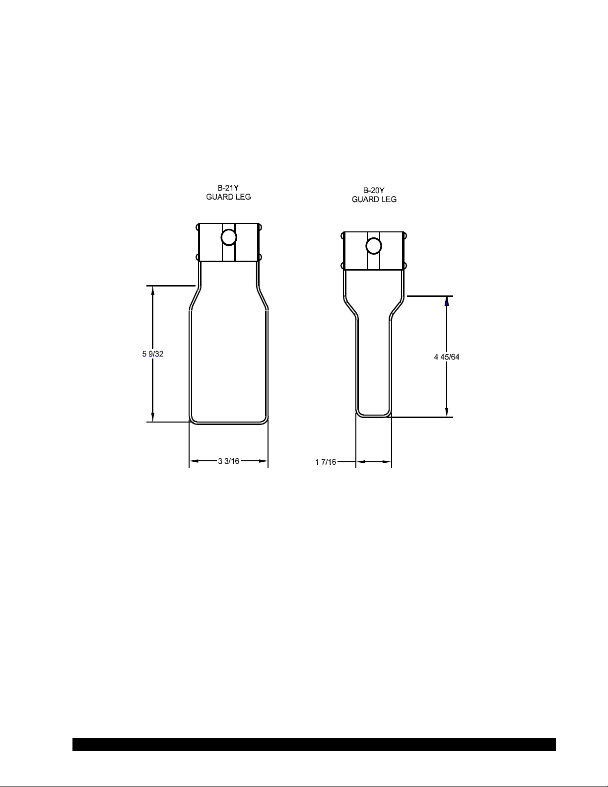
repeatable value can be obtained without any special effort for any measurement circumstance. But, it
should be known that this type of torque reading will not convert into a correct centipoise value when
using a Brookeld factor if the boundary conditions are not those specied by Brookeld.
The guard leg is a part of the calibration check of the Brookeld LV and RV series Viscometer/Rheometer.
Our customers should be aware of its existence, its purpose and the effect that it may have on data.
With this knowledge, the viscometer user may make modications to the recommended method of
operation to suit their needs.
Figure F-1
Brookeld Engineering Laboratories, Inc. Page 63 Manual No. M/07-022-D0613
Page 64

Appendix G - Communications
Serial and Analog Outputs
DV-I PRIME
No Connection
No Connection
Transmit Data
(TxD)
Cable Sense
Serial Ground
Notes:
1. This is a 0-1 volt d.c. output where 0 volts corresponds to 0% torque and 1
volt corresponds to 100 % torque with a resolution of 1 millivolt (0.1%).
2. This is a 4.00 volt d.c. output where 0 volts corresponds to -100°C and 4.00
volts corresponds to +300°C with a resolution of 1 millivolt (0.1°C).
1
6
2
3
4
5
Analog Ground
7
Analog % Torque
(Note 1)
8
Analog Temperature
(Note 2)
9
Serial Ground
-
Analog Output:
Figure G-1
The analog outputs for % torque is accessed from the 9-pin connector located on the rear panel
of the DV-I PRIME. The pin connections are shown in Figure G-1.
The output cable (Part No. DVP-96B) connections are:
Red Wire: Temperature Output (with temp. option)
Black Wire: Temperature Ground (with temp. option)
White Wire: % Torque Output
Green Wire: % Torque Ground
NOTE: Please contact Brookeld Engineering Laboratories or your local dealer/distributor
for purchase of the DVP-96B analog output cable.
When using the Brookeld Printer Cable (Brookeld Part No. DVP-81), the output rate is 1.0
times per second. The DV-I PRIME uses the following RS-232 parameters to output these strings:
Baud Rate 9600
Data Bits 8
Stop Bits 1
Parity None
Handshake None
Brookeld Engineering Laboratories, Inc. Page 64 Manual No. M/07-022-D0613
Page 65

Appendix H - Laboratory Stands with Parts Identication
1
2
Release Lever: Push
and hold here to
move up and down.
3
4
5
6
6
3
4
5
Model S Model Q
Item Part Number Description Qty.
1 VS-CRA-14S Rod and Clamp Assembly (Model S) 1
2 VSQA-001Y Rod and Clamp Assembly (Model Q)
†
3 GV-1201 Base, Models S and Q (includes 2 VS-3 leveling screws) 1
4 502028071S33B Flat washer 5/16 x 7/8 x .071” 1
5 50S311832S01B Screw, 5/16-18 x 1" lg. hex head 1
6 GV-1203 Leveling Screws, Model S and Q 2/2
1
Figure H-1
Brookeld Engineering Laboratories, Inc. Page 65 Manual No. M/07-022-D0613
Page 66

UNPACKING
Check carefully to see that all the components are received with no concealed damage.
1 Base, VS-2, with 2 Leveling Screws, VS-3, packed in a cardboard carton
1 Upright Rod, VS-34, with attached Clamp Assembly, VS-55Y, Mounting Screw and
2 Lock washers
ASSEMBLY
1. Remove the base assembly from the carton.
2. Remove the screw and washer from the upright rod. Place the rod and clamp assembly
into the hole in the top of the base.
NOTE: The “Front” designation on the clamp assembly should face the opening of the
legs, i.e., parallel to the leveling feet.
3. Rotate the rod/clamp assembly slightly until the slot on the bottom of the rod intersects
the pin located in the base.
4. While holding the rod and base together, insert the slotted screw and washer, as shown in
Figure H-1, and tighten securely.
5. Adjust the VS-28 tension screw on the clamp assembly so that it is not loose on the upright
rod.
VISCOMETER MOUNTING
Insert the Viscometer mounting rod into the hole (with the cut-away slot) in the clamp assembly.
Adjust the instrument level until the bubble is centered from right to left and tighten the clamp
knob (clockwise). Use the leveling screws to “ne” adjust the viscometer level.
NOTE: If the Digital Viscometer cannot be leveled, check to insure that the rod is installed
with the gear rack facing forward.
CAUTION: Do not tighten the clamp knob unless the viscometer mounting rod is inserted in
the clamp assembly.
NOTE: If the clamp is taken off the upright rod, the tension insert (Part No. VS-29) must be
properly aligned for the clamp to t back onto the upright rod.
When the tension insert (Part No. VS-29) is inserted, its slot must be in the vertical position parallel
to the upright rod. If the slot is not in the correct position, the clamp will not slide down over the
upright rod. Use a small screwdriver or pencil to move it into the correct position.
Brookeld Engineering Laboratories, Inc. Page 66 Manual No. M/07-022-D0613
Page 67

Appendix I - DVE-50A Probe Clip
Guard Leg
DVE-50A
Probe Clip
RTD Temperature
Probe
Probe Clip DVE-50A is supplied with the DV-I PRIME Optional Temperature Probe. It is used
to attach the RTD temperature probe to the LV/RV Guard Leg or 600 mL low form Grifn beaker.
Figure I-1 is a view of the Probe Clip, showing the hole into which the RTD probe is inserted,
and the slot which ts onto the LV/RV guard leg. When inserting the RTD probe into the Probe
Clip, the upper part of the Clip is compressed by squeezing the points shown in Figure I-1.
RTD Probe
Hole
Figure I-1
Figure I-2 shows the Probe Clip (with RTD temperature probe installed) mounted on the guard leg.
Figure I-3 shows the Probe Clip mounted in a 600 mL low form Grifn beaker. This mounting
may be used with LV, RV, HA and HB series instruments.
Squeeze Here when
installing RTD
Temperature Probe
Figure I-2 Figure I-3
NOTE: The RTD probe must be parallel to the beaker wall so as not to interfere with the
viscosity measurement.
RTD Temperature Probe
DVE–50
Probe Clip
Brookfield 600 mL Low Form
Griffin Beaker
Brookeld Engineering Laboratories, Inc. Page 67 Manual No. M/07-022-D0613
Page 68

Appendix J - Fault Diagnosis and Troubleshooting
Spindle Does Not Rotate
❏ Make sure the viscometer is plugged in.
❏ Check the voltage rating on your viscometer (115V, 220V): it must match wall voltage.
❏ Make sure the power switch is in the ON position.
❏ Verify rpm: make sure rotational speed (rpm) has been correctly selected.
Spindle Wobbles When Rotating or Looks Bent
❏ Make sure the spindle is tightened securely to the viscometer coupling.
❏ Check the straightness of all other spindles; replace them if bent.
❏ Inspect viscometer coupling and spindle coupling mating areas and threads for dirt: clean
threads on spindle coupling with a 3/56 left-hand tap.
❏ Inspect threads for wear; if the threads are worn, the unit needs service (see Appendix L).
❏ Check to see if spindles rotate eccentrically or wobble. There is an allowable run-out for
1/32-inch in each direction (1/16-inch total) when measured from the bottom of the spindle
rotating in air.
❏ Check to see if the viscometer coupling is bent; if so, the unit is in need of service.
If you are continuing to experience problems with your viscometer, follow this troubleshooting section
to help isolate the potential problem.
Perform an Oscillation Check
❏ Remove the spindle and turn the motor OFF.
❏ Gently push up on the viscometer coupling.
❏ Turn the coupling until the % on the display reads 15% - 20%.
❏ Gently let go of the coupling.
❏ Watch the % values decrease and rest at 0.0 (±0.1%)
If the viscometer does not rest at zero, the unit is need of service. See Appendix L for details on how
to return your viscometer.
Inaccurate Readings
❏ Verify Spindle, Speed and Model selection
❏ Verify test parameters: temperature, container, volume, and method. Refer to:
• “More Solutions to Sticky Problems”; Chapter 3, Section 3.4, Viscosity Measurement
Techniques
❏ Perform a calibration check. Follow the instructions in Appendix E.
• Verify tolerances are calculated correctly.
• Verify that calibration check procedures were followed exactly.
If the unit is found to be out of tolerance, the unit may be in need of service. See Appendix L for details
on how to return your viscometer.
Brookeld Engineering Laboratories, Inc. Page 68 Manual No. M/07-022-D0613
Page 69

Appendix K - Online Help and Additional Resources
www.brookeldengineering.com**
The Brookeld website is a good resource for additional information and self-help whenever you
need it. Our website offers a selection of “how to” videos, application notes, conversion tables,
instruction manuals, material safety data sheets, calibration templates and other technical resources.
http://www.youtube.com/user/BrookeldEng
Brookeld has its own YouTube channel. Videos posted to our website can be found here as well
as other “home-made” videos made by our own technical sales group.
Viscosityjournal.com
Brookeld is involved with a satellite website that should be your rst stop in viscosity research.
This site serves as a library of interviews with experts in the viscosity eld as well as Brookeld
technical articles and conversion charts. Registration is required so that you can be notied of
upcoming interviews and events, however, this information will not be shared with other vendors,
institutions, etc.
Article Reprints
- Available in Print Only
- Brookeld has an extensive library of published articles relating to viscosity, texture
and powder testing. Due to copyright restrictions, these articles cannot be emailed.
Please request a hardcopy of articles by calling our customer service department or by
emailing: marketing@brookeldengineering.com.
- Available online
- Brookeld has a growing number of published articles that can be downloaded directly
from the Brookeld website. These articles can be found on our main website by
following this path: http://www.brookeldengineering.com/support/documentation/
article reprints
More Solutions To Sticky Problems
Learn more about viscosity and rheology with our most popular publication. This informative
booklet will provide you with measurement techniques, advice and much more. It’s a musthave for any Brookeld Viscometer or Rheometer operator. More Solutions is available
in print and/or as a downloadable pdf on the Brookeld website by following this path:
http://www.brookeldengineering.com/support/documentation
Training/Courses
Whether it is instrument-specic courses, training to help you better prepare for auditing concerns,
or just a better understanding of your methods, who better to learn from than the worldwide
leaders of viscosity measuring equipment? Visit our Services section on our website to learn
more about training.
**Downloads will require you to register your name, company and email address. We respect
your privacy and will not share this information outside of Brookeld.
Brookeld Engineering Laboratories, Inc. Page 69 Manual No. M/07-022-D0613
Page 70

Appendix L- Warranty Repair and Service
Warranty
Brookeld Viscometers are guaranteed for one year from date of purchase against defects in
materials and workmanship. They are certied against primary viscosity standards traceable to
the National Institute of Standards and Technology (NIST). The Viscometer must be returned to
Brookeld Engineering Laboratories, Inc. or the Brookeld dealer from whom it was purchased
for no charge warranty service. Transportation is at the purchaser’s expense. The Viscometer
should be shipped in its carrying case together with all spindles originally provided with the
instrument. If returning to Brookeld please contact us for a return authorization number prior
to shipping, failure to do so will result in a longer repair time.
For a copy of the Repair Return Form, go to the Brookeld website,
www.brookeldengineering.com
For repair or service in the United States return to:
Brookeld Engineering Laboratories, Inc.
11 Commerce Boulevard
Middleboro, MA 02346 U.S.A.
Telephone: (508) 946-6200 FAX: (508) 923-5009
www.brookeldengineering.com
For repair or service outside the United States consult Brookeld Engineering Laboratories, Inc. or the
dealer from whom you purchased the instrument.
For repair or service in the United Kingdom return to:
Brookeld Viscometers Limited
Brookeld Technical Centre
Stadium Way
Harlow, Essex CM19 5GX, England
Telephone: (44) 1279/451774 FAX: (44) 1279/451775
www.brookeld.co.uk
For repair or service in Germany return to:
Brookeld Engineering Laboratories Vertriebs GmbH
Hauptstrasse 18
D-73547 Lorch, Germany
Telephone: (49) 7172/927100 FAX: (49) 7172/927105
www.brookeld-gmbh.de
For repair or service in China return to:
Guangzhou Brookeld Viscometers and Texture Instruments Service Company Ltd.
Suite 905, South Tower, Xindacheng Plaza
193 Guangzhou Da Dao Bei, Yuexiu District
Guangzhou, 510075 P. R. China
Telephone: (86) 20/3760-0548 FAX: (86) 20/3760-0548
www.brookeld.com.cn
On-site service at your facility is also available from Brookeld. Please contact our Service
Department in the United States, United Kingdom, Germany or China for details.
Brookeld Engineering Laboratories, Inc. Page 70 Manual No. M/07-022-D0613
Page 71

Appendix M - Viscosity Test Report
Brookeld Engineering Laboratories, Inc. Page 71 Manual No. M/07-022-D0613
 Loading...