

Page 1

BROOKFIELD DIGITAL RHEOMETER
MODEL DV-III+ Operating Instructions
Manual No. M/98-211-A0701
Please record the Model and Serial Number of your viscometer.
Having this information readily available will help us to assist you
should there be any questions regarding your instrument.
Model No. ______________________
Serial No. ______________________
SPECIALISTS IN THE
MEASUREMENT AND
CONTROL OF VISCOSITY
BROOKFIELD ENGINEERING LABORATORIES, INC.
11 Commerce Boulevard, Middleboro, MA 02346-1031 USA
TEL508-946-6200
F
AX
508-946-6262
Brookfield Engineering Laboratories, Inc. Page 1 Manual No. M/98-211-A0701
or 800-628-8139 (USA excluding MA)
NTERNET
I
www.brookfieldengineering.com
Page 2

Contents
I. INTRODUCTION.......................................................................................................3
I.1 Components ............................................................................................................. 4
I.2 Utilities..................................................................................................................... 5
I.3 Specifications ........................................................................................................... 5
I.4 Data Retention.......................................................................................................... 5
I.5 Set-Up ...................................................................................................................... 6
I.6 Connections.............................................................................................................. 9
I.7 Key Functions ........................................................................................................ 10
II. GETTING STARTED...............................................................................................12
II.1 Autozero................................................................................................................. 12
II.2 Rheometer Display................................................................................................. 13
II.3 Spindle Entry.......................................................................................................... 15
II.4 Direct Speed Entry ................................................................................................. 16
II.5 External Control..................................................................................................... 17
III. MAKING VISCOSITY MEASUREMENTS ..............................................................19
III.1 Quick Start ............................................................................................................. 19
III.2 Preparation ............................................................................................................. 19
III.3 Selecting a Spindle/Speed...................................................................................... 20
III.4 Multiple Data Points .............................................................................................. 20
III.5 Cleaning ................................................................................................................. 20
IV. PROGRAMMING THE DV-III+ AND ANALYSIS..................................................... 21
IV.1 Programming Concept ........................................................................................... 21
IV.2 DV-III Speed/Time Pair Programming .................................................................. 22
IV.3 Bevis Programs ...................................................................................................... 34
IV.4 Choosing the Best Data Collection Method........................................................... 36
IV.5 Data Analysis ......................................................................................................... 37
V. OPTIONS ................................................................................................................ 40
V.1 Set Up..................................................................................................................... 40
V.2 Print ........................................................................................................................41
V.3 Alarms .................................................................................................................... 42
V.4 Set Temperature ..................................................................................................... 43
V.5 Data ........................................................................................................................ 43
V.6 Timed data collection ............................................................................................. 44
VI. RHEOLOADER USER'S MANUAL ........................................................................ 47
VI.1 Description of B.E.V.I.S. Commands .................................................................... 47
VI. 2 Example Programs ................................................................................................. 50
APPENDIX A - Cone/Plate Rheometer Set-Up..................................................................... 52
APPENDIX B
APPENDIX C - Variables in Viscosity Measurements .......................................................... 61
APPENDIX D - Spindle and Model Codes ............................................................................ 63
APPENDIX E - Calibration Procedures ................................................................................ 67
APPENDIX F - VS-27Y Clamp Assembly............................................................................ 74
APPENDIX G - DV-III+ to Computer Command Set .......................................................... 75
APPENDIX H - Fault Diagnosis and Troubleshooting.......................................................... 77
APPENDIX I - Warranty Repair and Service ....................................................................... 80
- Viscosity Ranges.......................................................................................... 56
Brookfield Engineering Laboratories, Inc. Page 2 Manual No. M/98-211-A0701
Page 3

I. INTRODUCTION
The Brookfield DV-III+ Programmable Rheometer measures fluid parameters of Shear Stress and
Viscosity at given Shear Rates. Viscosity is a measure of a fluid’s resistance to flow. You will find
a detailed description of the mathematics of viscosity in the Brookfield publication “More Solutions
to Sticky Problems”, a copy of which was included with your DV-III+.
The principle of operation of the DV-III+ is to drive a spindle (which is immersed in the test fluid)
through a calibrated spring. The viscous drag of the fluid against the spindle is measured by the
spring deflection. Spring deflection is measured with a rotary transducer. The measuring range of
a DV-III+ (in centipoise) is determined by the rotational speed of the spindle, the size and shape of
the spindle, the container the spindle is rotating in, and the full scale torque of the calibrated spring.
There are four basic spring torque series offered by Brookfield:
Spring Torque
Model dyne•cm mN•m
LVDV-III+ 673.7 0.0673
RVDV-III+ 7,187.0 0.7187
HADV-III+ 14,374.0 1.4374
HBDV-III+ 57,496.0 5.7496
The higher the torque calibration, the higher the measurement range. The measurement range for
each torque calibration may be found in Appendix - B.
All units of measurement are displayed according to either the CGS system or the SI system.
1. Viscosity appears in units of centipoise (shown as “cP”) or milliPascal-seconds (shown
as mPa•s).
2. Shear Stress appears in units of dynes/square centimeter (“D/cm
2
”) or Newtons/square
meter (“N/m2”).
3. Shear Rate appears in units of reciprocal seconds (“1/SEC”).
4. Torque appears in units of dyne-centimeters or Newton-meters (shown as percent “%”
in both cases).
The equivalent units of measurement in the SI system are calculated using the following conversions:
SI CGS
Viscosity: 1 mPa•s = 1 cP
Shear Stress: 1 Newton/m
2
= 10 dyne/cm
2
Torque: 1 N•m = 107 dyne•cm
References to viscosity throughout this manual are done in CGS units.
WARNING: Use of this instrument in a manner not specified by Brookfield may result in incorrect
readings or instrument failure. Please read this manual prior to using the instrument.
Brookfield Engineering Laboratories, Inc. Page 3 Manual No. M/98-211-A0701
Page 4

I.1 Components
Component Part Number
DV-III+ Rheometer depends on model
Powerbase DVP-2Y
includes:
Leveling Screws (3) VS-3
Upright Rod VS-20
Jam Nut VS-21
Clamp Assembly VS-27Y
Spindle Set with Case
LVDV-III+ set of four spindles or SSL
RVDV-III+ set of seven spindles or SSR
HA/HBDV-III+ set of seven spindles SSH
For Cone/Plate versions: a spindle wrench, one cone spindle and sample cup Part No.
CPE-44Y replace the spindle set.
Power Cord
for 115 VAC DVP-65
for 230 VAC DVP-66
RTD Temperature Probe DVP-94Y
Ribbon Cable DVP-145
Guard Leg:
LVDV-III+ B-20Y
RVDV-III+ B-21Y
Carrying Case DVP-71Y
RHEOLOADER Software DVP-201Y
Cable (DV-III+ to Computer) DVP-80
Operator Manual M/98-211
Please check to be sure that you have received all components, and that there is no
damage. If you are missing any parts, please notify Brookfield Engineering or your local
Brookfield agent immediately. Any shipping damage must be reported to the carrier.
Brookfield Engineering Laboratories, Inc. Page 4 Manual No. M/98-211-A0701
Page 5

I.2 Utilities
Autosensing Power Supply:
Input Voltage: 90 - 260 VAC
Input Frequency: 50 - 60 Hz
Power Consumption: Less than 220 UA
Power Cord Color Code:
United States Outside United States
Hot (live) Black Brown
Neutral White Blue
Ground (earth) Green Green/Yellow
I.3 Specifications
Speed Range: 0.01-250 RPM, 0.01 RPM increments from 0.01 to 0.99 RPM,
0.1 RPM increments from 1.0 to 250 RPM
Viscosity Accuracy: ± 1.0% of full scale range for a specific spindle running at a
specific speed.
Temperature sensing range: - 100°C to 300°C (-148°F to 572°F)
Temperature accuracy: ± 1.0°C from -100°C to 150°C
± 2.0°C from +150°C to 300°C
Analog Torque Output: 0 - 1 Volt DC (0 - 100% torque)
Analog Temperature Output: 0 - 4 Volts DC (10mv / °C)
Printer Output: Centronics, serial
Computer Interface: RS232
Weight: Gross Weight: 35 lbs. 15.9 kg
Net Weight: 32 lbs. 14.5 kg
Carton Volume: 2.0 cu. ft. 0.057 m
3
I.4 Data Retention
The DV-III+ will save spindle parameters (used to calculate centipoise, shear rate and shear stress),
default settings and the test data from the last program test run when the rheometer is turned off or
there is a power failure.
Brookfield Engineering Laboratories, Inc. Page 5 Manual No. M/98-211-A0701
Page 6
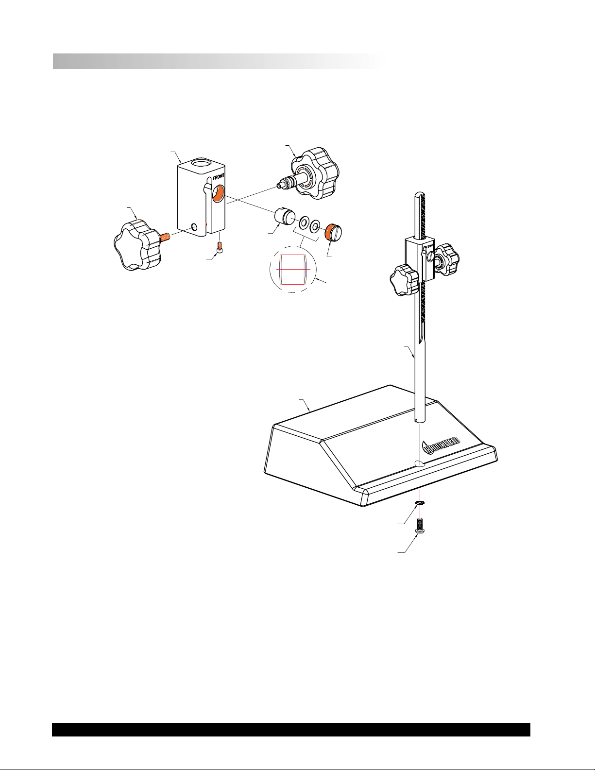
I.5 Set-Up
1) Place the upright rod into the hole at the front of the base. The rack gear and clamp assembly
should face the rear of the base (see Figure 1). The upright rod is held in place with the jam nut
which is attached from the bottom of the base. Tighten this nut with a suitable wrench (spanner).
VS-41Y
CLAMP KNOB
ASSEMBLY
VS-35
UNIVERSAL
CLAMP
50S044012E140
4-40 x 3/8 LG.
SOC. HD. CAP SCREW
VS-40Y
GEAR SCREW
ASSEMBLY
VS-29
TENSION
INSERT
BASE UNIT
VS-28
TENSION
SCREW
VS-29W
WASHER
(2 REQ'D.)
VS-34
UPRIGHT ROD
502020032S34Z
WASHER, EXT. TOOTH,
5/16 O.D. x 5/32 I.D.
50S311B24S06B, SCREW,
5/16 - 18x3/8 LG. SLT. PAN HD.
Figure 1
Brookfield Engineering Laboratories, Inc. Page 6 Manual No. M/98-211-A0701
Page 7
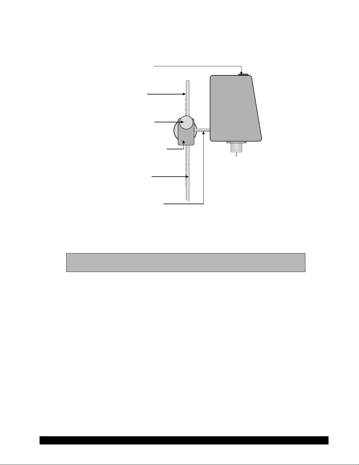
2) Insert the mounting handle on the back of the DV-III+ into the hole on the clamp assembly
(Figure 2).
Bubble Level
Rack Gear
Clamp Screw
Clamp Assembly
Upright Rod
Mounting Handle
Figure 2
3) Tighten the DV-III+ clamp Screw (Figure 2).
Note: If the clamp assembly moves along the upright rod too freely, tighten the
tension screw (see Appendix F).
4) Insert the ribbon cable into the DV-III+ Rheometer head. Insert the other end of the ribbon
cable into the connector on the DV-III+ base (see Figure 3).
Brookfield Engineering Laboratories, Inc. Page 7 Manual No. M/98-211-A0701
Page 8
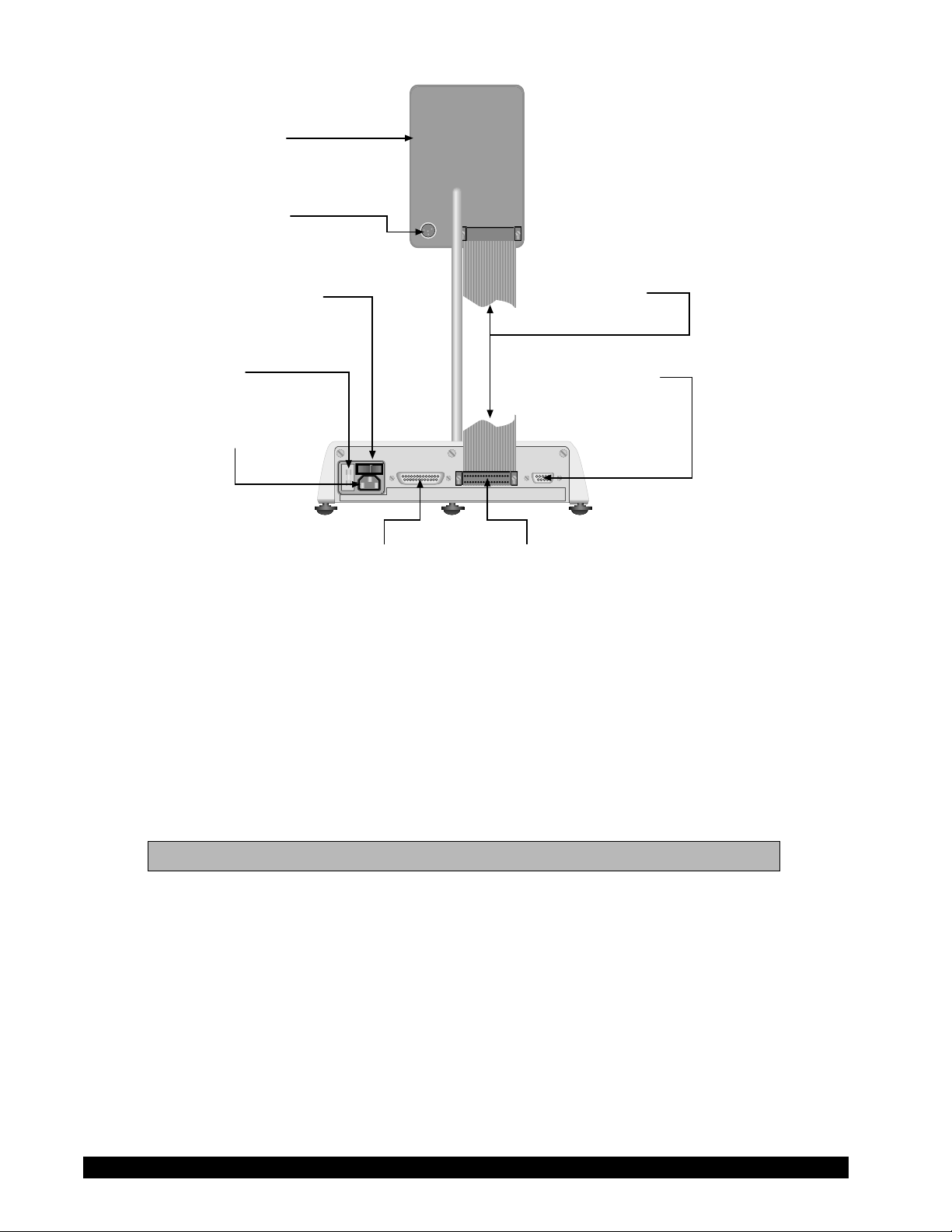
Rheometer Head
RTD Temperature
Probe Connector
Power ON/OFF Switch
AC Fuse(s)
AC Power Connector
100-240 VAC 50/60 HZ 220VA
Connector Connector
Parallel Printer Ribbon Cable
MODEL DV-III BASE UNIT
Ribbon Cable
Connector
RS-232 Serial
Printer/Computer
Analog Output(s)
240 CUSTHING ST.
STOUGHTON, MA USA 02072
Figure 3
5) Connect the RTD probe to the socket on the back side of the DV-III+ Rheometer (Figure 3).
6) The Rheometer must be leveled before the instrument is zeroed and readings are taken. The level
is adjusted using the three leveling screws on the base. Adjust so that the bubble level on top of
the DV-III+ (Figure 2) is centered within the circle.
7) Make sure that the AC power switch at the rear of the base unit is in the OFF position. Connect
the AC plug to the socket on the back of the DV-III+ base and plug it into the appropriate AC line.
The DV-III+ must be earth grounded to ensure against electronic failure!!
8) Temperature monitoring is assured (after the instrument has stabilized) to within ±1.0°C in the
range -100°C to +150°C and within 2°C in the range 150°C to 300°C.
9) For Cone/Plate models refer to Appendix A.
10) For printers, software and temperature controllers, refer to Section 1.6, Connections.
Brookfield Engineering Laboratories, Inc. Page 8 Manual No. M/98-211-A0701
Page 9

I.6 Connections
The DV-III+ Rheometer is capable of communicating with several external devices to enhance
operation. The cables and connections required for proper communication are detailed below.
RHEOLOADER SOFTWARE
DVP-80 cable is used to connect the RS232 serial port on the DV-III+ base to Com Port 1 or Com
Port 2 on the computer. This cable is supplied with the DV-III+.
RHEOCALC SOFTWARE
DVP-80 cable is used to connect the RS232 serial port on the DV-III+ base to Com Port 1 or Com
Port 2 on the computer. This cable is supplied with the RHEOCALC software.
PARALLEL PRINTER
CAP-86 cable is used to connect the 25-pin parallel port on the DV-III+ base with the Centronics
port on the printer.
SERIAL PRINTER
DVP-81 cable is used to connect the 9-pin serial port on the DV-III+ with the 25-pin serial port on
a printer.
THERMOSEL CONTROLLER, MODEL HT-106
TC-200/TC-500/TC-201P/TC-501P BATH, MODEL HT-107
DVP-141 cable is used to connect the serial port on the DV-III+ base to the serial port on the
controller. This cable is supplied with the controller/bath.
Be sure that the controller temperature probe is properly located in the control device (Thermosel
or bath) and connected to the controller.
Notes: 1. The controller may alternately communicate with Rheocalc V 2.0 soft-
ware. In this configuration, the controller is connected to the computer
through either Com Port 1 or Com Port 2. The DV-III+ is also connected
to a computer Com Port.
2. The controller must also be connected to the control device (Thermosel or
bath) with the appropriate load cable.
STRIP CHART RECORDER
DVP-96Y cable is used to connect the serial port on the DV-III+ to the input block of the strip chart
recorder. This cable is supplied with a Brookfield strip chart recorder.
Brookfield Engineering Laboratories, Inc. Page 9 Manual No. M/98-211-A0701
Page 10
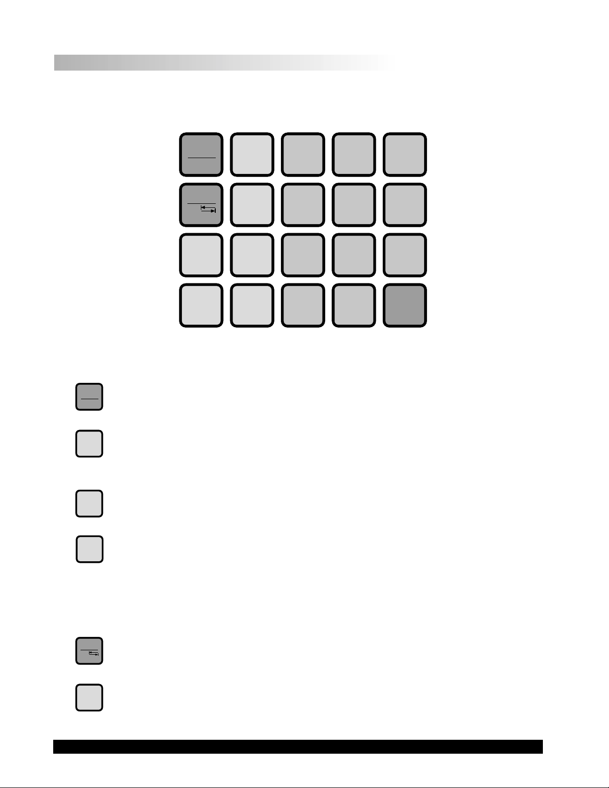
I.7 Key Functions
Figure 4 shows the control keys on the face of the DV-III+ Rheometer. The following describes
each key’s function.
MOTOR
ON/OFF
ESCAPE
MOTOR
ON/OFF
ESCAPE
OPTION
TAB
SELECT
SPDL
SELECT
DISP
AUTO
RANGE
PROG
PROG
RUN
PRINT
789
456
1
YES NO
.
2
0
3
ENTER
Figure 4
MOTOR ON/OFF, ESCAPE
Turns the motor on or off. Cancels any operation, returns the user to the previous screen.
RANGE
SELECT
SELECT
OPTION
TAB
AUTORANGE
AUTO
Presents the maximum (100% torque) viscosity attainable using the selected spindle at
the current speed.
SELECT SPDL
SPDL
Allows selection of the spindle to be used.
SELECT DISP
DISP
Selects the parameter to be displayed:
% Rheometer Torque (%)
cP Viscosity (cP or mPa.s)
SS Shear Stress (Dynes/cm2 or Newtons/m2)
SR Shear Rate (1/Sec)
OPTION, TAB
Accesses options menu. See Section V. Toggles between selectable items when indicated.
PRINT
PRINT
Sends a single line of data to an attached printer. Selects printing and non-printing mode as
selected in the Options menu.
Brookfield Engineering Laboratories, Inc. Page 10 Manual No. M/98-211-A0701
Page 11

PROG
PROG
Access the Programs menu for program creation, running or deleting. Contstructs a test
program. Allows you to review/modify an existing test program. Execute a Bevis program.
PROG
PROG RUN
RUN
Execute DV-III speed/time pair program.
0
NUMBER KEYS (0 through 9)
Sets speeds and choose items from various dialog screens and the option menu.
ENTER
ENTER
Functions as an ENTER key similar to a computer by serving to accept a keyboard entry.
Brookfield Engineering Laboratories, Inc. Page 11 Manual No. M/98-211-A0701
Page 12
II. GETTING STARTED
II.1 Autozero
Before readings may be taken, the Rheometer must be autozeroed. This is done each time the power
switch is turned on. The Rheometer will guide you through the procedure, as follows:
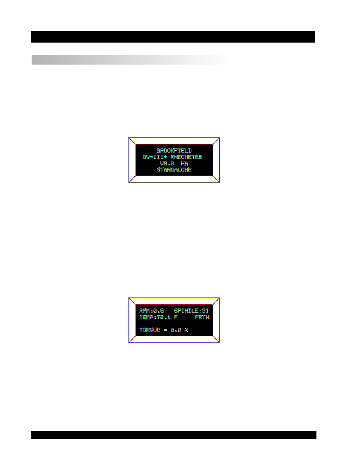
Turn power switch on; as shown in Figure 5, the screen indicates that the DV-III+ is in the standalone
mode (is not connected to a computer) and gives the version of the operating firmware (the built in
program which controls the instrument) and a two-digit alphanumeric code which indicates the
Model number (see Table D2 in Appendix D; the code tells the spring torque rating of your
Rheometer).
Figure 5
No key press is necessary. After a short pause the display will read “REMOVE SPINDLE, LEVEL
RHEOMETER AND PRESS THE MOTOR ON/OFF KEY TO AUTOZERO.” Before beginning the autozero
procedure, Brookfield recommends that you allow 10 minutes for the instrument to warm up.
After pressing the MOTOR ON/OFF key, the screen “flashes” for approximately 15 seconds while
the DV-III+ autozeros.
After 15 seconds the display reads “AUTOZERO IS COMPLETE REPLACE SPINDLE AND PRESS ANY
KEY.” Press a key.
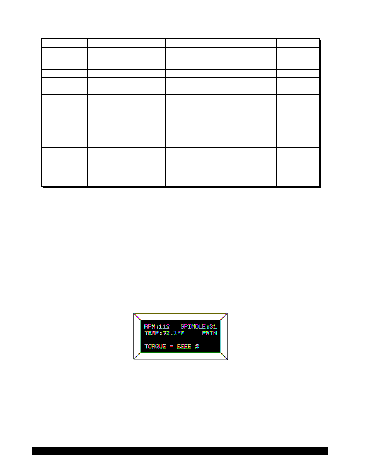
The main screen is displayed and the DV-III+ is ready for use (Figure 6).
Figure 6
Brookfield Engineering Laboratories, Inc. Page 12 Manual No. M/98-211-A0701
Page 13

II.2 Rheometer Display
The DV-III+ Rheometer is supplied with a 4-line display. The basic set of information is called "The
Default Screen" and is shown in FIGURE 7. The parameters are detailed below:
1
3
5
2
4
6
Figure 7
1. Motor Status and Current Rheometer Speed
The DV-III+ motor can be OFF, ON at 0.0 rpm or ON at a speed greater than 0.0 rpm. When the
motor is OFF, "OFF" will be displayed and no speed entry will be accepted. When the motor is
ON, the actual speed of rotation will be displayed. When the motor is switched from ON to OFF,
the speed of rotation will be remembered; when the motor is turned ON again, the DV-III+ will
operate at that same speed. The rheometer motor is set to "OFF" after AUTOZERO.
Note: Motor OFF and a speed setting of 0.0 are essentially the same.
2. Spindle Number
The currently-selected spindle. Viscosity, shear rate, and shear stress values will be calculated
based on this number. See Section II.3.
3. Measured Temperature
The current temperature as measured by the attached temperature probe. If no probe is connected,
four dashes "----" will be displayed.
4. Printing Status
Indicates the currently-selected method of printing. See Section II.5.
5. Measured Data
Instrument Torque (%), Viscosity (cP), Shear Stress (D/cm2), Shear Rate (s-1)
The parameters are toggled from one to another using the Select Display key.
Note: Shear Stress and Shear Rate data cannot be calculated for some spindle
geometries. In these cases, the display will show 0.0.
6. Blank Line
This line is used to display entry data when selecting a spindle or speed of rotation. Additionally,
selected programs available for running will be identified here when in the Program mode. (See
Section IV.2).
The default screen will appear at the completion of the AUTOZERO sequence each time the DVIII+ is turned ON in the standalone mode (see Section II.6 for external control mode). The displayed
data may be changed as described in the following sections.
The format for data displayed in the default screen and all other screens is described in Table 1. For
appearance sake, the entries in the table have been decimal point aligned. Actual rheometer display
will have all fields left justified.
Brookfield Engineering Laboratories, Inc. Page 13 Manual No. M/98-211-A0701
Page 14
p
q
y
pp
p
Item Print Format ExampleRange
RPMRPM
0.01 <= RPM <= 0.99
0.09X.XX
XX.X 0.1 <= RPM <= 99.9 2.4
XXX.X 100 <= RPM <= 250 150.0
Model
S
indle
Tor
ue
Viscosit
M
S
T
cP or mPas
XXXXX
XX
XX.X
X.XX
XXX.X
XXXXX
See Model Table D2 - A
00 <= S <= 99
-10.1 <= T <= 99.9
0 <= cP <= 9.99
10 <= cP <= 999.9
1000 <= cP <= 99999
D
31
82.4
3.16
123.8
12345
XXXeX 100000 <= cP <= 51200000000 123e3 to 8
Shear Stress
Shear Rate 1/SEC
Tem
Time
Time
erature T
D/CM2 or
N/M2 =
D/CM2/10
Z
XXX.X
XXXXX
0 <= D/CM2 <= 9.99X.XX
10 <= D/CM2 <= 999.9
1000 <= D/CM2 <= 99999
4.56
234.5
12345
XXXeX 100000 <= D/CM2 <= 999999 123e3
X.XXX 0 <= 1/SEC <= 9.999
XX.X
XXXXX
XXX.X
10 <= 1/SEC <= 99.9
100 <= 1/SEC <= 99999
-99.9 <= T <= 300.0 -10.3
1.234
20.7
200
XX:XX 00:00 <= Z <= 99.59 05:32
Table 1
OUT OF RANGE INDICATORS
The DV-III+ is capable of measuring instrument torque within the range of 0 to 100%. Based on
this measurment, viscosity and shear stress are calculated. Brookfield recommends that data be
collected only in the range of 10 to 100%. Any data collected outside of this range is considered
invalid.
RV
The DV-III+ provides the following display indicators when the measurement point is outside of
the 10-100% acceptable range.
TORQUE GREATER THAN 100%
When Rheometer torque exceeds 100%, the parameter display field will show “EEEE” for torque,
viscosity and shear stress.
Figure 8
TORQUE LESS THAN 10%
When Rheometer torque drops below ten (10) percent, the Rheometer will continue to display
measurement (%, cP, D/cm2) values with units flashing:
Brookfield Engineering Laboratories, Inc. Page 14 Manual No. M/98-211-A0701
Page 15
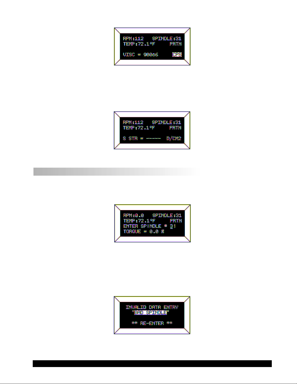
Figure 9
TORQUE LESS THAN 0%
When Rheometer torque drops below zero (0) percent, the Rheometer will continue to display
torque values preceded by a minus (-) sign. The viscosity and shear stress field will display dashes
(- - - - ) as indicated in the next screen display:
Figure 10
II.3 Spindle Entry
The user can elect to change the spindle selection by pressing the SELECT SPDL key. The DV-III+
control program will use the previously blank line 3 on the default display screen to record the new
spindle input as depicted in Figure 11.
Figure 11
To enter a spindle number, press the numeric keys until the desired spindle number has been entered.
Valid spindle numbers encompass the range from 00 to 99 as listed in Appendix D. Mistakes are
corrected by repeatedly pressing the numeric keys until the proper spindle value has been entered.
At that point, the user presses the SELECT SPDL key again. An invalid spindle entry will result in
a “beep” and the display of the data entry error screen as depicted below.
Figure 12
Brookfield Engineering Laboratories, Inc. Page 15 Manual No. M/98-211-A0701
Page 16
An invalid spindle entry is any two digit number in the range from 01 to 99 which is not listed in
Appendix D. This error message will be displayed for a few seconds after which the spindle entry
screen (Figure 11) will be re-displayed with a blank field for the spindle number. The user can
cancel spindle entry at any time by pressing the MOTOR ON/OFF/ESCAPE key.
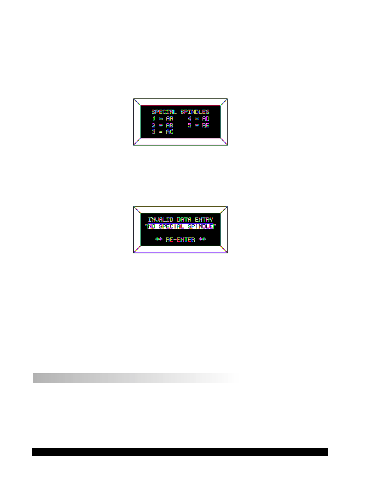
The user may elect to use a special spindle whose selection is accomplished by first entering a
spindle number of 99 and then pressing the
SELECT SPDL key. This will result in the following
display:
Figure 13
At this point, press the numeric key for the special spindle of choice. This list is created at the time
the Rheometer is manufactured. This list will therefore depend on the number of special spindles
ordered and could contain as few as one (1) or as many as five (5) spindles. If no special spindles
were purchased, the following message will be displayed if 99 is entered for a spindle number:
Figure 14
Press any key to exit this screen and to return to the spindle selection screen. The user may again
select another spindle or press the SELECT SPDL key to cancel spindle selection operation.
Successful selection of a spindle at the press of the SELECT SPDL key returns the user to the default
screen with the new spindle displayed in the upper right-hand corner. For standard spindles this
would be the two (2) digit designator used to select the spindle. In the case of special spindles, the
two (2) letters (AA, AB, AC, AD or AE) corresponding to the special spindle would be displayed
instead. The spindle number or letters will be retained in memory when power is removed. This
means that the last value entered for the spindle will be displayed the next time the Rheometer is
turned on.
II.4 Direct Speed Entry
At this point, the user may choose to enter a speed by the so-called direct speed entry method. Enter
a valid speed in the range of 0.01 to 250 RPM by pressing the numeric keys successively. The
previously blank line 3 on the default display screen records the user’s new speed input as depicted
in Figure 15:
Brookfield Engineering Laboratories, Inc. Page 16 Manual No. M/98-211-A0701
Page 17
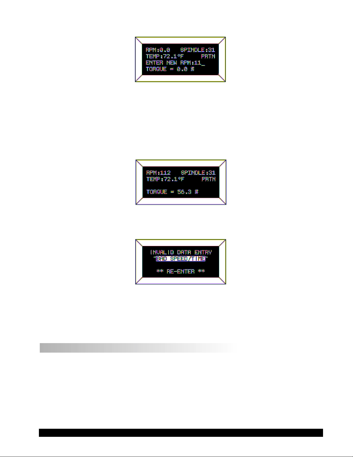
Figure 15
Here, the user intends to enter a speed of 112 RPM, has pressed the “1” key twice and is about to
press the “2” key. If the user makes more than five (5) key presses, the DV-III+ control program
will “roll” the cursor back to the first character of the field and begin to overwrite the previous data
entry.
Next the user presses the ENTER key to accept the speed. The motor will begin running at 112 RPM
and the display will be updated to the next screen image:
Figure 16
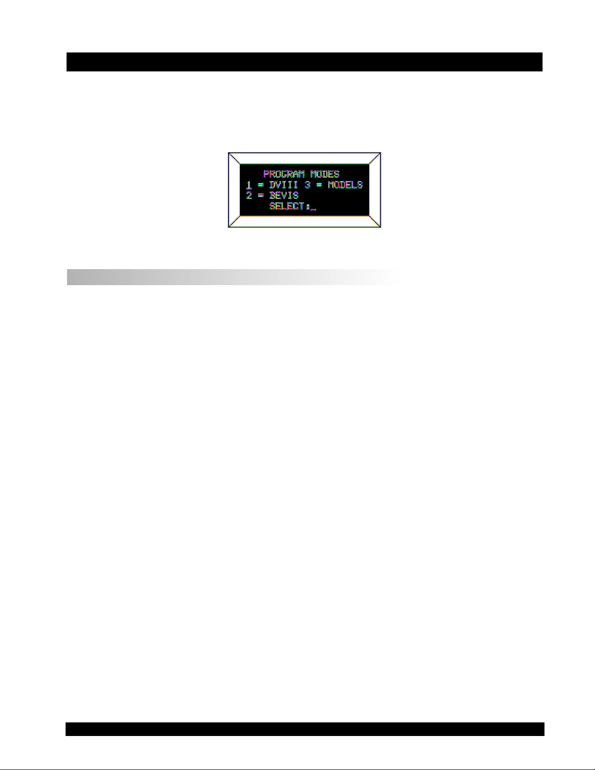
If the speed entered was not valid the Rheometer will display the following message:
Figure 17
After a few seconds, the display returns to Figure 15 with the speed data field cleared and just the
underscore cursor awaiting a new entry.
II.5 External Control
The DV-III+ Rheometer can be used in conjunction with Brookfield software, RHEOCALC (V. 2.
or higher). Through RHEOCALC, all rheometer functions are controlled by the computer. The DVIII+ must be set to the external control mode to allow for proper communication with RHEOCALC.
To configure the external control mode, connect cable DVP-80 to the serial port on the DV-III+ base
before turning on the DV-III+. With the DVP-80 cable in place, the DV-III+ will present the screen
shown in Figure 18 when it is turned on. If external control is selected, the DV-III+ will display
Figure 19 and only accept control commands from RHEOCALC software.
Brookfield Engineering Laboratories, Inc. Page 17 Manual No. M/98-211-A0701
Page 18
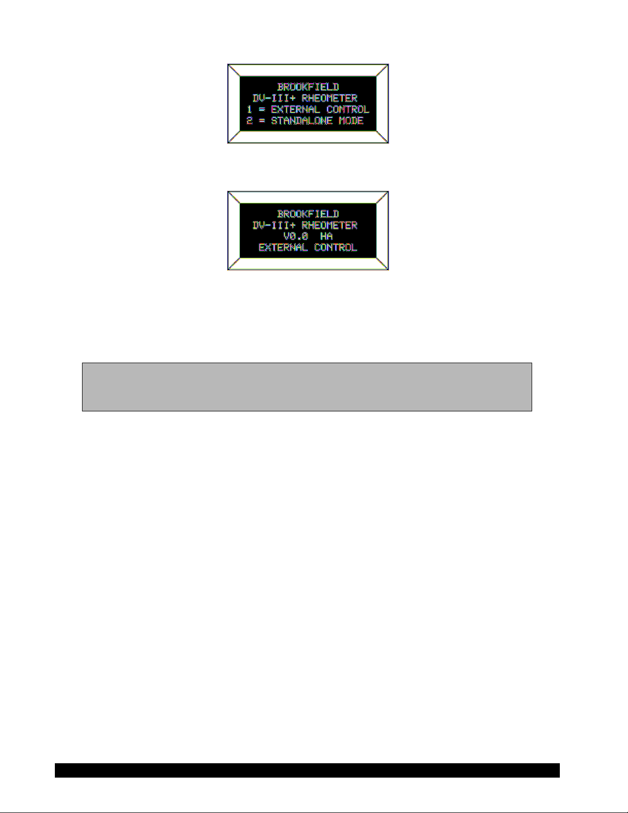
Figure 18
Figure 19
The DV-III+ may be set to stand alone mode by turning it OFF and ON again and selecting "Stand
Alone" or by removing the DVP-80 cable prior to turning the DV-III+ on.
Note: The DV-III+ cannot communicate with RHEOLOADER software in the external
control mode. Chose "Stand Alone" when presented with Figure 18 if you want
to use RHEOLOADER.
Brookfield Engineering Laboratories, Inc. Page 18 Manual No. M/98-211-A0701
Page 19

III. MAKING VISCOSITY MEASUREMENTS
III.1 Quick Start
The DV-III+ Rheometer uses the same methodology as the Brookfield Dial Reading Viscometer
and DV series of Digital Viscometers. If you have experience with other Brookfield equipment, this
section will give you the quick steps for taking a viscosity reading. If you have not used a Brookfield
Viscometer before, skip this section and go to Section III.2 for a detailed description.
A) Assemble and level the rheometer (Section I.5).
B) Autozero the rheometer (Section II.1).
C) Enter the spindle number using the SELECT SPINDLE key (Section II.3).
D) Introduce the spindle into the sample and attach the spindle to the coupling nut.
NOTE: Left-hand threads.
E) Enter the speed of rotation using the number pad and ENTER key (Section 11.4).
F) Record % torque and viscosity.
III.2 Preparation
A) RHEOMETER: The DV-III+ should be turned on, leveled and autozeroed. The level is
adjusted using the three feet on the bottom of the base and confirmed using the bubble on the
top of the head. Adjust the feet until bubble is inside the center target. Set the level prior to
autozero and check the level prior to each measurement.
Proper level is essential for correct operation of the DV-III+.
B) SAMPLE: The fluid to be measured (sample) must be in some container. Many spindle systems
from Brookfield are supplied with specific sample chambers such as the Small Sample Adapter,
UL Adapter and Thermosel. The standard spindles supplied with the DV-III+, LV (1-4), RV
(1-7) and HA/HB (1-7), are designed to be used with a 600ml low form Griffin beaker (or
equivalent container with a diameter of 8.25 cm).
Brookfield recommends that you use the appropriate container for the selected spindle. You
may choose to use an alternate container for convenience, however, this may have an effect on
the measured viscosity. The DV-III+ is calibrated considering the specified container.
Alternate containers will provide results that are repeatable but not "true."
The LV (1-4) and RV (1-7) are designed to be used with the guardleg attached. Measurements
made without the guardleg will provide repeatable results but may not provide "true" results.
When comparing data with others, be sure to specify the sample container and presence/
absence of the guardleg.
Many samples must be controlled to a specific temperature for viscosity measurement. When
conditioning a sample for temperature, be sure to temperature control the container and spindle
as well as the sample.
Please see our publication, "More Solutions to Sticky Problems", for more detail relating to
sample preparation.
Brookfield Engineering Laboratories, Inc. Page 19 Manual No. M/98-211-A0701
Page 20

III.3 Selecting a Spindle/Speed
The DV-III+ has the capability of measuring viscosity over an extremely wide range (for
example, the RVDV-III+ can measure fluids within the range of 100-40,000,000 cP) (see
Appendix B). This range is achieved through the use of several spindles over many speeds.
The process of selecting a spindle and speed for an unknown fluid is normally trial and error.
An appropriate selection will result in measurements made between 10-100 on the
instrument % torque scale. Two general rules will help in the trial and error process.
1) Viscosity range is inversely proportional to the size of the spindle.
2) Viscosity range is inversely proportional to the rotational speed.
In other words: to measure high viscosity, choose a small spindle and/or a slow speed. If the
chosen spindle/speed results in a reading above 100%, then reduce the speed or choose a smaller
spindle.
Experimentation may reveal that several spindle/speed combinations will produce satisfactory
results between 10-100%. When this circumstance occurs, any of the spindles may be selected.
Non-Newtonian fluid behavior can result in the measured viscosity changing if the spindle and/
or speed is changed. See our publication, "More Solutions to Sticky Problems," for more detail.
When viscosity data must be compared, be sure to use the same spindle, speed, container
and temperature.
III.4 Multiple Data Points
The majority of viscosity measurements are made at the quality control level and consist of a
single data point. The test is conducted with one spindle at one speed. The data point is a useful
bench mark for the go/no-go decision in a production setting. The DV-III+ can be used for
single point measurement.
Many fluids exhibit a characteristic change in viscosity with a change in applied force. This
non-Newtonian flow behavior is commonly seen in paints, coatings and food products as a
decrease in viscosity as shear rate increases. This behavior cannot be detected or evaluated with
the single viscosity point measurement.
Non-Newtonian flow is analyzed through the collection of viscosity data over a range of shear
rates and the generation of a graph of viscosity versus shear rate (a rheogram). This information
will allow for a more complete characterization of a fluid and may help in formulating and
production of the product. The DV-III+ is capable of collecting multiple data points for the
analysis of flow behavior. See Section IV on Programming and Analysis.
More information on flow behavior, shear rate and rheograms is available in our publication,
"More Solutions to Sticky Problems."
III.5 Cleaning
All immersed components are stainless steel. Use cleaning solutions that are not corrosive and
avoid scratching the measurement surfaces. The instrument housing should be cleaned with a
soft damp cloth.
Brookfield Engineering Laboratories, Inc. Page 20 Manual No. M/98-211-A0701
Page 21
IV . PROGRAMMING THE DV -III+ AND ANAL YSIS
The programming and data analysis functions of the DV-III+ are accessed by pressing the PROG key
on the rheometer. The display will change to present a menu with three choices: DV-III, B.E.V.I.S., and
Models. DV-III and B.E.V.I.S. are the programming alternatives. Models will present the five math
models available for data analysis.
Figure 20
IV.1 Programming Concept
The DV-III+ may be programmed to collect viscosity data without operator involvement. The
captured data may be displayed and analyzed or output to a printer. Programs may be written using
two different methodologies, DV-III and B.E.V.I.S.
The DV-III programming technique uses speed/time pairs to control the DV-III+. A program
consists of multiple lines (up to 25) instructing the rheometer to operate at a particular speed for some
period of time. As an example, we can instruct the DV-III+ to rotate the spindle at 5 RPM for 30
seconds and then change speed to 10 RPM and wait 20 seconds with the following program:
Step 1 RPM = 5 Time = 00:30
Step 2 RPM = 10 Time = 00:20
A single data point will be collected at the end of each time interval.
The B.E.V.I.S. programming technique uses a custom program language to control the DV-III+. A
program consists of a series of commands instructing the rheometer in speed control, time control,
data collection, temperature control, and output. B.E.V.I.S. offers a higher level of rheometer
control compared to the DV-III method. However, the construction of B.E.V.I.S programs is more
involved. The 2-step DV-III program previously described is duplicated using B.E.V.I.S. commands below:
SSN 5
WTI 00:30
PDN
SSN 10
WTI 00:20
PDN
END
The involved programming of B.E.V.I.S. commands is a small trade for the significant increase in
control capability over the DV-III method.
Brookfield Engineering Laboratories, Inc. Page 21 Manual No. M/98-211-A0701
Page 22

IV.2 DV-III Speed/Time Pair Programming
This programming method allows the operator to control the DV-III+ through the variables of speed
and time. These speed/time pairs instruct the rheometer to operate at a speed of rotation for a certain
period of time. Programs can be created with up to 25 steps. The DV-III+ can store up to 10
programs. Upon completion of a program, the data may be viewed on the DV-III+ display, analyzed
or printed to an attached parallel or serial printer.
Two examples of programs are shown below:
Collect Data Over Time Collect Data At Several Speeds
Step RPM Time Step RPM Time
1 100 00:12 1 2.5 01:00
2 100 00:12 2 5 00:30
3 100 00:12 3 10 00:30
4 100 00:12 4 20 00:15
5 100 00:12 5 50 00:15
Five viscosity data points Five viscosity data points will be
will be collected over collected at five speeds over
one minute. 150 seconds.
This program mode is accessed by pressing the program key and selecting number 1; 1 = DV-III.
The creation, editing and execution of DV-III programs are described in the following sections.
There are two types of test programs:
1) Next Speed Set where the test speeds are programmed, and the operator must signal the DV-
III+ to change speeds (and therefore take a reading) by pressing the ENTER key.
2) Prog Speed Set where the DV-III+ will perform the test automatically.
Each step of a program has two variables - speed and hold time. The reading is taken at the end of
the hold time interval in a Prog Speed Set or when the ENTER key is pressed in a Next Speed Set.
If the first step hold time interval is 0 seconds, the program is a Next Speed Set type. If the first step
interval is 1 second or more, the program is a Prog Speed Set type.
SPEED SET SELECTION AND PROGRAMMING
The DV-III+ viscometer allows for the retention of a maximum of 10 speed sets with up to 25
discrete speeds per speed set. The program locations are numbered 0 through 9. These speed sets
are retained in EEPROM memory for those times when the DV-III+ is not powered up. To access
a previously programmed speed set or to enter data for a new speed set, the user presses the “1” key
when in the display of Figure 20 and is presented with the screen shown in Figure 21:
Brookfield Engineering Laboratories, Inc. Page 22 Manual No. M/98-211-A0701
Page 23
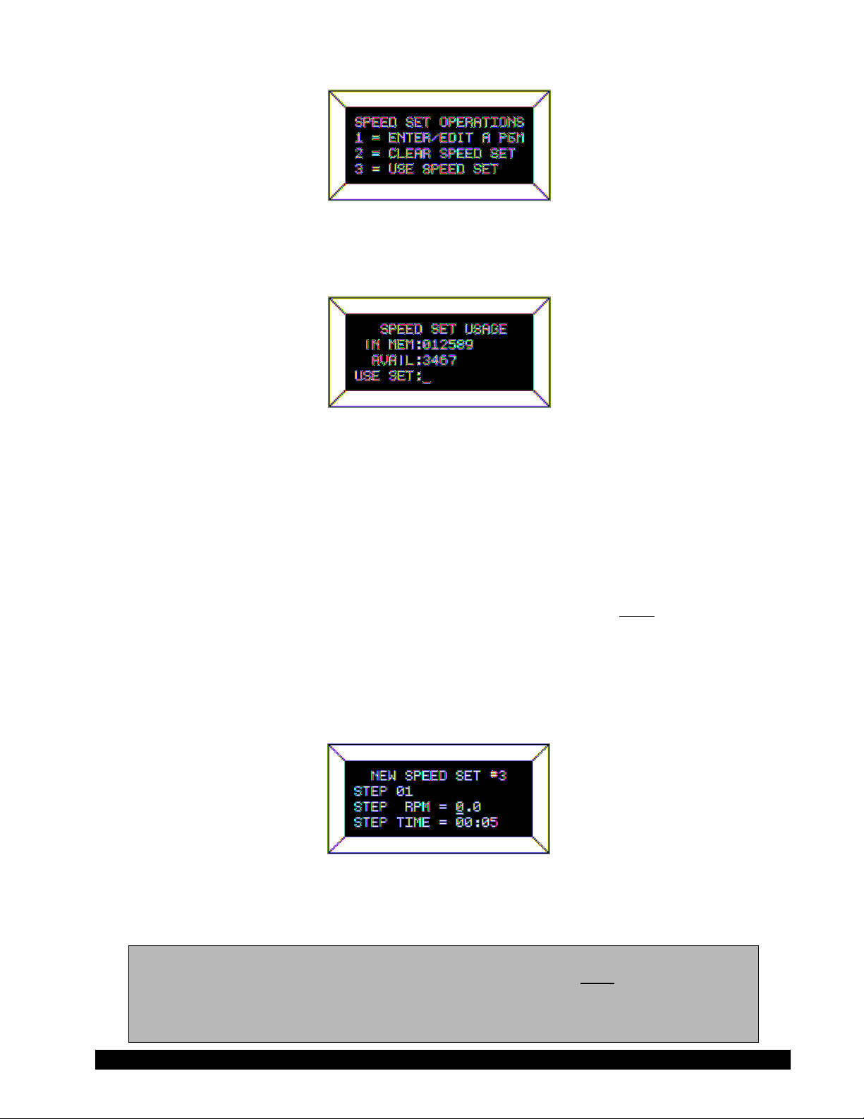
Figure 21
At this point, the user may Enter/Edit, Clear or Use a stored program (Speed Set). Let’s startwith
Enter/Edit by pressing the “1” key:
Figure 22
In this example, the user is informed that he has 6 speed sets (0,1,2,5,8,9) pre-programmed in
memory and 4 speed sets (3,4,6,7) not programmed and available. Select any one of the ten speed
sets by pressing the appropriate numeric key. Pressing the MOTOR ON/OFF/ESCAPE key at this
point would exit the user to the default PROGRAM MODES display (Figure 20). For now let’s
assume that the user wants to program a new speed set by pressing the “3” key (the first available
program slot).
ENTERING A SPEED SET (PROGRAM)
There are two (2) types of programs available to the user: programs with finite step time intervals
and programs with zero (0) step time intervals. We will cover the inputting of finite step time
programs first.
SPEED SETS WITH FINITE STEP TIMES (PROG SPEED)
These programs when executed will automatically progress from step to step based on the time
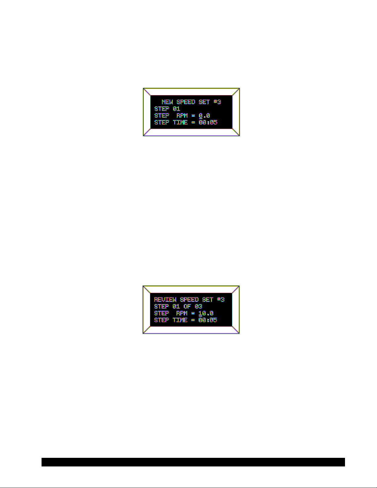
intervals programmed by the user. On pressing the “3” key in Figure 22 the user is presented with:
Figure 23
This screen reminds the user of the speed set that he has selected to program and then allows him
to change either the speed or time interval or both for that step.
Note: The time interval on entry to this screen will always be set to 00:05 seconds as the
default value. The user may of course change it to any valid time of his choice.
Whenever you change time interval, that new time becomes the default interval until
it is again changed by the user. Also, note that zero (0) times are not allowed for
program steps after the first step for Finite Step programs.
Brookfield Engineering Laboratories, Inc. Page 23 Manual No. M/98-211-A0701
Page 24
The OPTION/TAB key is used for moving from input field to input field and the ENTER key to accept
the current input for a step. On entry to this screen, the underscore cursor would be flashing (as
shown) under the first digit of the step RPM. Use the numeric keys to make changes to the step speed,
repeating the input as many times as required until satisfied.
When satisfied with the speed input, press the
OPTION/TAB key which moves the flashing cursor
down to the first character of the time field. The same procedure is used here to input the step time
as was used to enter the RPM above. Speed or time data that is out of range, as defined by Table
1, will result in the following screen:
Figure 24
This screen will be displayed for 1-3 seconds.
When ready, the user may press the PROG RUN key to display the data for the next step in the
program, or the MOTOR ON/OFF/ESCAPE key (whereby none of the changes up to that point will be
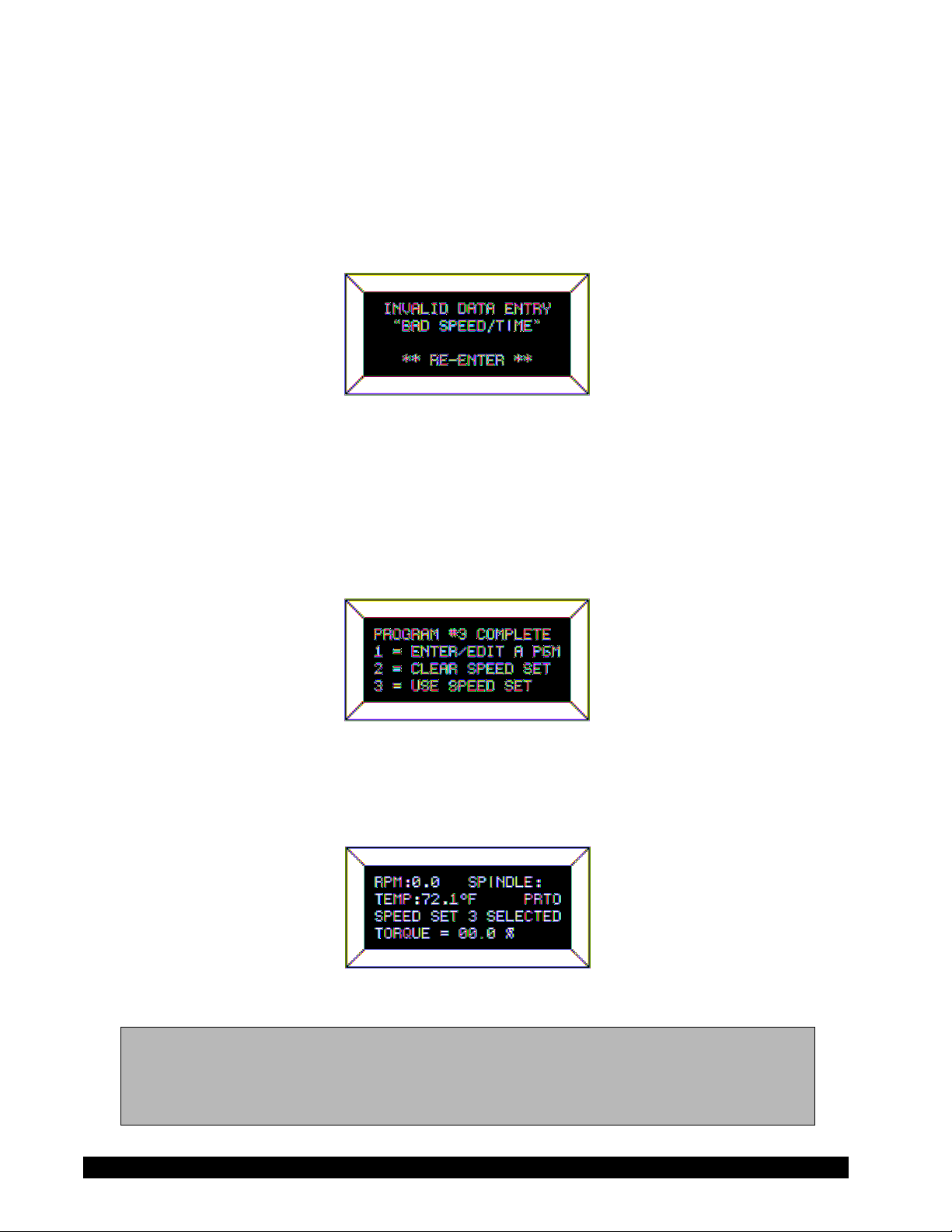
accepted) to return to the screen of Figure 22. To end a program, the user simply enters and accepts
a step RPM and Time of zero (0) or continues to input step data until the program reaches the twentyfive (25) step program limit. In either case, the following screen will be displayed:
Figure 25
To use the currently selected speed set, press the “3” key in Figure 25. This would immediately
revert to the default screen modified as follows:
Figure 26
Note: If at this point, prior to using the program the user wished to enter a direct speed, a
press of any numeric key which would result in a display similar to Figure 15. At
the completion of the direct speed input, the display would revert to Figure 26 above
with the appropriate RPM displayed, and the viscometer running at that speed.
Brookfield Engineering Laboratories, Inc. Page 24 Manual No. M/98-211-A0701
Page 25
The program is initiated by pressing the PROG RUN key. See "Using Pre-programmed Speeds."
SPEED SETS WITH ZERO STEP TIMES
These programs when executed will require that the user press the ENTER key to progress from step
to step. On pressing the “3” key in Figure 22 the user is presented with the same screen that he saw
in the above description for finite step programs:
Figure 27
The user inputs his step RPM exactly as he did for finite step time programs above. However, for
time, input 00:00 and press the ENTER key. From this point forward, the user will only be able to
enter speeds since each press of the ENTER key will advance him to the next step. The OPTION/TAB
key will not be required. If the user wishes to correct the speed input, continue to press the numeric/
decimal point keys until satisfied. To correct a speed after pressing the ENTER key for that step, wait
until the program is complete and then edit the program to correct the mistake. To end a program,
simply enter and accept a step RPM of zero (0) or continue to input step data until the program
reaches the twenty-five (25) step program limit. Speed restrictions/limits are the same as for the
description just above as are the error messages.
EDITING A SPEED SET (PROGRAM)
This item is used to review a just-entered program or to review/modify (edit) a program already
stored in a memory slot. Entry to this method would typically be from Figure 22 after selecting an
“IN MEM” program slot or by pressing the “1” key in Figure 21 having just finished entering a
program. In either case, the user is presented with:
Figure 28
Operation in this mode is exactly the same as for entering a new speed set; all key actions and speed
and time limits are the same. At this point, the user may continue to review/modify the speeds
comprising speed set #3 or elect to print a listing of the speeds in this speed set. To accomplish this,
the user must be in the program Enter/Edit mode; have selected or programmed a speed set which
contains more than two (2) speeds, and then press the PRINT key. If all is well (i.e. satisfied the above
requirements) the rheometer will display:
Brookfield Engineering Laboratories, Inc. Page 25 Manual No. M/98-211-A0701
Page 26

Figure 29
This message simply asks the user to make sure the printer is ready (it’s on-line and has paper in it)
and then awaits for the PRINT key to be pressed. When it is pressed, the DV-III+ will send the
following data to the attached printer:
FOR SPEED SETS WITH FINITE STEP TIMES
Program Use: __________________________________________________
Programmer:______________________________
BROOKFIELD DV-III+ RHEOMETER — DATA FOR SPEED SET #9
SPEED #01 RPM = 2.5 TIME INTERVAL = 00:05
SPEED #02 RPM = 5.0 TIME INTERVAL = 00:05
SPEED #03 RPM = 10.0 TIME INTERVAL = 00:05
SPEED #04 RPM = 20.0 TIME INTERVAL = 00:05
SPEED #05 RPM = 50.0 TIME INTERVAL = 00:05
FOR SPEED SETS WITH ZERO STEP TIMES
Program Use: __________________________________________________
Programmer:______________________________
BROOKFIELD DV-III+ RHEOMETER — DATA FOR SPEED SET #8
SPEED #01 RPM = 10.0 TIME INTERVAL = 00:00
SPEED #02 RPM = 20.0 TIME INTERVAL = 00:00
SPEED #03 RPM = 30.0 TIME INTERVAL = 00:00
SPEED #04 RPM = 40.0 TIME INTERVAL = 00:00
Since speed sets can contain twenty-five (25) separate speeds, printing the speeds that comprise a
speed set will be of great help in allowing the user to fully exercise the power of the DV-III+. After
the printing is complete, the user will be returned to the display of Figure 28.
CLEARING A SPEED SET FROM MEMORY
Since 10 speed sets can be retained in memory, the user may eventually use all the available speed
set slots. The user may also have programmed speed sets that are no longer required and would like
to remove. Assume that the user had programmed a new speed set #3 above. If he wished to
permanently remove that new speed set, or any other IN MEMORY speed set he would, while in
the screens of Figure 21, press the “2” key and be presented with:
Figure 30
Brookfield Engineering Laboratories, Inc. Page 26 Manual No. M/98-211-A0701
Page 27

This screen advises that there are 7 speed sets in memory; speed set #3 is in use and that the DVIII+ is awaiting input for the speed set to delete.
Note: If no speed set is in use the word “NONE” will appear next to the IN USE: prompt.
At this point, the user has two options:
1. Pressing the MOTOR ON/OFF/ESCAPE key will exit from this screen and no speed sets will
be cleared. Or
2. Pressing any of the keys “0”, “1”, “2”, “3”, “5”, “8”, or “9” will delete that speed set.
Thus, to discard speed set #5, the user would press the “5” key and be presented with:
Figure 31
In which the DV-III+ is requesting that the user specifically press the “1” key in order to delete the
desired speed set.
Figure 32
Pressing the “3” key will cause the DV-III+ to take no action will return the user to the CLEAR
SPEED SET opening screen, Figure 30. Any attempt to delete an in-use speed (“3” for instance)
will cause the DV-III+ to issue a “beep” “beep” with no action being taken. Thus no active (i.e.
selected for use) program can be deleted from this screen.
USING PRE-PROGRAMMED SPEEDS
Pressing the three (3) key from Figure 21 takes the user to the speed set selection screen of Figure
22 where the user selects a new speed set. That done the user is sent to the default screen with:
“SPEED SET X SELECTED” displayed on line three (3) of the screen.
The user initiates the use of programmed speeds by pressing the PROG RUN key. If the user presses
the PROG RUN key with no speed set selected, the following error box will be displayed:
Brookfield Engineering Laboratories, Inc. Page 27 Manual No. M/98-211-A0701
Page 28

Figure 33
However, we will assume at this point that we have selected speed set #2 for use in the ensuing data
gathering operations. To initiate the use of this speed set (with finite step times or with zero step
times), the user presses the PROG RUN key and is presented with a start/end step input screen as
shown next:
Figure 34
If the user had not previously entered start and end steps, this screen will display 01 for the start step,
and the last program step (13 in this case) as the end step. The user could elect to use the entire speed
set at this point by pressing the PROG RUN key. If the user had previously selected a start and end
step, those values would be displayed upon entry to this screen instead of the program limit values
as shown above. However, while a speed set can contain up to 25 separate speeds, the user may
be in a situation where only a few contiguous steps may be required. Therefore, this screen allows
for the option of entering the range of speeds encompassed by the start step (not necessarily the first
step) and the end step (not necessarily the last step). Pressing any numeric key at this point will
erase the currently displayed start step and substitute the new value. The user may select a start step
less than the end step ( a so-called Up Ramp) or a start step greater than the end step ( a so-called
Down Ramp). Any attempt to enter a start or end speed not contained in the speed set will result
in the following display:
Figure 35
The ENTER key is used to step from the start step entry to the end step entry. Repeated pressing
of the ENTER key will allow the user to move back-and-forth between the start and end entries and
change them as required until the correct start and end step values have been entered. The selected
speed set, and the start and end steps values entered, will be retained in EEProm memory for use the
next time the viscometer is powered up in the stand-alone mode. Pressing the OPTION/TAB key at
this point results in the following screen display:
Brookfield Engineering Laboratories, Inc. Page 28 Manual No. M/98-211-A0701
Page 29

Figure 36
LOCKOUT OPTIONS
Pressing the “1” key locks out any use of the NUMERIC keys, and the PROGRAM, SELECT
SPINDLE
and OPTIONS/TAB keys. Pressing the “3” key would disable an existing lockout condition
only when in the LOCKOUT OPTIONS screen, Figure 36. After pressing the “1” or “3” keys the
user would be returned to the display of Figure 34. From Figure 34 the user runs the program by
pressing the PROGRAM RUN key which signifies that the user is satisfied with his start and stop step
values, and wishes to start running with the selected speed set. Or, he can return to the default screen
of Figure 7 by pressing the MOTOR ON/OFF/ESCAPE key. (Note: the OPTIONS/TAB key is reenabled at this point
only to allow the user to return to the LOCKOUT OPTIONS screen). In either
case, if the user has enabled the lockout mode, the top line of the default display will change as shown
in Figure 37 below:
Figure 37
The “LOCKOUT” condition will remain in effect until the user re-starts the program mode by
pressing the PROGRAM RUN key re-initiating the steps of Figures 34 through 37 above.
Once the start and end steps have been selected, the program is started by pressing the PROG RUN
key. However, if the viscometer motor was not turned on, the following message would be
displayed:
Figure 38
At this point, the user would turn the viscometer motor on by pressing the MOTOR ON/OFF/
ESCAPE key. This will cause the viscometer to start running at the first selected program speed.
Brookfield Engineering Laboratories, Inc. Page 29 Manual No. M/98-211-A0701
Page 30

USING PROGRAMMED SPEEDS WITH A ZERO TIME INTERVAL
Assume the following:
• A speed set has been selected.
• A subset of the speed set has not been selected. (i.e. we will use the entire set of speeds)
• The speed set included a time interval that was equal to zero minutes and zero seconds.
• Print mode has been set to non-continuous mode (i.e. output will be sent to the printer only
when the user presses the ENTER key).
With the above items in effect our default display screen will appear as follows after the
PROGRAM steps have been completed:
Figure 39
Or, if the user had selected the LOCKOUT option, the default screen above would appear as in
Figure 40 below:
Figure 40
Here, the LOCKOUT mode is indicated by the revision to the top line of Figure 40 where
“SPINDLE” has been contracted to “SPDL” and the two-letter combo: “LK” is being used to
indicate the “LOCKOUT” condition. Please note that while TORQUE is presently being
displayed, there is nothing to prevent the user from pressing the SELECT DISP key to change the
data display item.
The item to note here is the message being displayed on line 3 informing the user that the program
is at speed #02 of the 12 speeds comprising speed set #02. The DV-III+ will continue to operate
at 112 RPM until the ENTER key is pressed. At that point (pressing the ENTER key), two distinct
events will occur:
1. The DV-III+ will ramp up (or down) to programmed speed #03 and,
2. Since the printer is On (PRTN), the data corresponding to the last speed (112 RPM) that existed
at the time the ENTER key was pressed will be sent to the attached printer.
Thus, if 12 speeds comprised the selected speed set, then the user would be required to press the
ENTER key 12 times to exercise the entire speed set. After the last speed has been executed (i.e.
the user pressed the ENTER key for the twelfth time), the viscometer speed will be set at ZERO RPM
and the following message will be displayed:
Brookfield Engineering Laboratories, Inc. Page 30 Manual No. M/98-211-A0701
Page 31

Figure 41
Pressing the ENTER key would return the user to the default screen, as depicted in Figure 40, or to
the program start and stop limit selections of Figure 34 if the PROG RUN key is pressed.
USING PROGRAMMED SPEEDS WITH A NON-ZERO TIME INTERVAL
Assume the following:
• A speed set has been selected.
• A subset of the speed set has not been selected. (i.e. we’ll use all of the speeds in the speed set)
• The speed set included a time interval that was greater than zero (0) minutes and zero (0) seconds.
• Print mode has been set to non-continuous mode (i.e. output will be sent to the printer only when
the user presses the ENTER key).
With the above items in effect our default display screen will appear as follows after the program
steps have been completed:
Figure 42
The difference between this mode and the zero time interval mode is reflected in the message being
displayed on line three of the display where PROG has replaced ENTER indicating that the
program will be executed step-by-step without user intervention. Here the user is again informed
that he is at speed #02 of the 12 speeds comprising speed set #02. As the programmed time interval
elapses, the following will occur:
• The DV-III+ will ramp up (or down) to programmed speed #03 and,
• The data corresponding to the last speed (speed #02) that existed at the moment the step time
elapsed will be sent to the printer since the printer is ON (PRTN) (The automatic ramping to the
next speed will be interpreted by the DV-III+ as if the ENTER key had been pressed, causing the
printer output).
• At the completion of the speed set, the viscometer speed will be set at ZERO RPM
After the last speed has been executed, the viscometer speed will be set at ZERO RPM and the
following message will be displayed:
Brookfield Engineering Laboratories, Inc. Page 31 Manual No. M/98-211-A0701
Page 32

Figure 43
Pressing the ENTER key would return the user to the default screen, as depicted in its general form
in Figure 42, or to the program start and stop limit selections of Figure 34 if the PROG RUN key
is pressed.
OPERATION WITH PROGRAMMED SUBSET SPEEDS
Had the user selected a subset of a speed set (Figure 34), say speeds #04 through #08, then the
programmed mode (with a non-zero time interval) would result in the following display:
Figure 44
Here, the user is informed that speed set #2 is being used starting with speed number four and ending
at speed #08 while currently executing speed #04. After the first speed (number #04) is completed,
the display would be updated to show the new speed and the step display would now reflect the
current executing step number as in Figure 45 below.
Figure 45
If the speed set contained no time interval, the selection of a subset of speeds would result in a screen
display as shown in Figure 46.
Figure 46
Brookfield Engineering Laboratories, Inc. Page 32 Manual No. M/98-211-A0701
Page 33

The step number would be incremented each time the user pressed the ENTER key. Assume that the
speed corresponding to step #04 was executing. If the user presses the ENTER key, our display will
be updated as shown in Figure 47
Figure 47
PROGRAMMED SPEED STOP
The user may stop program mode operation at any time by pressing the MOTOR ON/OFF/ESCAPE
key anytime during program operation. The following message would be displayed:
Figure 48
The viscometer motor would be automatically turned OFF and the default screen display (Figure
37) would show zero (0.0) RPM. At this point, the user may perform any valid viscometer operation
- load a new speed set; run a direct speed; set alarms or even re-start the current program.
PROGRAMMED SPEED HOLD
The user may interrupt program mode operation at any time by pressing the PROG key during
program execution. The following message would be displayed:
Figure 49
The viscometer motor would be automatically turned OFF and the DV-III+ would be awaiting user
key input. If the user presses the “1” key, the DV-III+ will continue executing the current program,
picking up from whichever RPM (and time, if applicable) it had been interrupted. However, if
the user had pressed the “3” key, operation would be identical to that described above for
Programmed Speed Stop mode.
Brookfield Engineering Laboratories, Inc. Page 33 Manual No. M/98-211-A0701
Page 34

IV.3 Bevis Programs
The B.E.V.I.S. Programming Method allows the operator to control the DV-III+ through the
variables of speed, temperature and time while providing for independent data collection.
Programs can include up to 25 commands with a maximum data count of 800. The DV-III+ can
store up to 10 programs. Upon completion of the program the data may be viewed on the DVIII+ display, analyzed or printed to an attached parallel or serial printer.
B.E.V.I.S. programs are created on a PC using Rheoloader software (supplied with the DVIII+). See Section VI for details. The programs are "loaded" onto the DV-III+. Loaded programs cannot be deleted, but can be overwritten.
The B.E.V.I.S. program menu is accessed by pressing the PROG key and selecting number 2, 2
= B.E.V.I.S. The loading and execution of B.E.V.I.S. programs are described in the following
sections.
B.E.V.I.S. PROGRAMS MENU
B.E.V.I.S. operations are accessed by pressing the “2” key when in the PROGRAM MODES
menu. The user is immediately presented with:
Figure 50
This screen informs the user that the B.E.V.I.S. program in storage slot 3 is current (“last used”) and
that it may be run by pressing the “2” key or another program may be selected by pressing the “2”
key. It should be noted that entrance to the B.E.V.I.S. program mode makes the last used program
available for printing or running. Thus the user, seeing that a program was resident in slot 3, could
have printed it directly from the above screen by pressing the front panel PRINT key.
SELECTING AND DOWNLOADING B.E.V.I.S. PROGRAMS
To select a program the user presses the “1” key and is presented with:
Figure 51
The user is informed that the current (or “last used”) program is no. 3; that programs 0,1,2,3 and 4
are available for immediate use and that five (5) slots: 5,6,7,8 and 9 are empty and are available for
download from a host computer. A press of the ENTER key would select the current program (i.e.
“3”) for use while a press of an appropriate numeric key 0,1,2,3 and 4 would select that specific
Brookfield Engineering Laboratories, Inc. Page 34 Manual No. M/98-211-A0701
Page 35

program slot for use. The above screen would be updated to reflect the new selection. A press of
the 5,6,7,8 or 9 keys will place the user in the B.E.V.I.S. program download mode. The following
screen appears (assuming a press of the “5” key):
Figure 52
The user’s selection “5” is flashing and is the current slot selection. When ready, the user presses
the
ENTER key to begin the program download. The following screen will appear for the duration
of the download. See Section VI. RHEOLOADER for information on creating and downloading
B.E.V.I.S. programs.
Figure 53
RUNNING B.E.V.I.S. PROGRAMS
Programs are run by pressing the “2” key when in Figure 50 which presents the user with the
following screen:
Figure 54
Here we see that our program is no. “3” and that a press of the ENTER key will start it running. As
soon as the program starts executing the user will be presented with:
Figure 55
This is a typical display for a given program step. The current step being executed (WTI0330) is
shown as well as the next step to be executed (PDN). The bottom line displays the current program
Brookfield Engineering Laboratories, Inc. Page 35 Manual No. M/98-211-A0701
Page 36

step, the total number of steps (02/39) and any time intervals if they are relevant. The WKY
command message could be displayed on the bottom line in lieu of the step and time info. This screen
stays resident until the user presses the OPTIONS/TAB key which “toggles” back-and-forth between
this screen and an amended default screen shown next:
Figure 56
The user now sees viscosity data and can use the SELECT DISPLAY key to view other viscosity
measurement parameters. Pressing the OPTIONS/TAB key from now on will toggle between the
screens of Figure 55 and Figure 56. The program code will automatically switch back to the
program progress screen, Figure 55 above, if a conditional has been reached, the end of a program
step is reached or user input is required. If no user input is required, the B.E.V.I.S. program proceeds
to the next step without switching back to the progress screen.
IV.4 Choosing the Best Data Collection Method
The DV-III+ offers 3 methods for data collection; Single Speed, DV-III Speed/Time Pairs and
B.E.V.I.S. Programs. The decision of which technique is best should be made considering the
test requirements.
SINGLE SPEED
Single speed measurements may be made by direct speed commands on the DV-III+ keypad.
Viscosity and % Torque are read directly from the display. This technique offers the simplicity of
the Brookfield Dial Viscometer. Multiple data points may be gathered by issuing multiple speed
commands.
This technique is fast and easy. It's well suited to gathering data on samples prior to establishing a test method or for performing single point tests.
DV-III SPEED/TIME PAIRS
DV-III speed/time pairs offers a simple technique to collect multiple data points. Programs can be
created and executed from the DV-III+ keypad. Results can be analyzed or output to a printer.
This technique is useful when multiple data points are required and the test method is simple.
B.E.V.I.S. PROGRAMS
B.E.V.I.S. Programs offer a command set capable of sophisticated rheometer control and data
collection. Programs are created on a PC and executed from the DV-III+ keypad. Results can be
analyzed or output to a printer.
The B.E.V.I.S. Program technique is useful when sophisticated data collection is necessary.
Brookfield Engineering Laboratories, Inc. Page 36 Manual No. M/98-211-A0701
Page 37

IV.5 Data Analysis
Data collected from DV-III speed/time pairs or B.E.V.I.S. programs may be analyzed using several
math models. These models provide a means to numerically describe the behavior of the test fluid.
In the case of viscosity measurement, a non-Newtonian fluid will produce a curve when test data
is plotted on a shear stress vs. shear rate graph. The math model will force the data into a straight
line and describe it with a slope and y intercept. The terminology associated with the slope and y
intercept vary from model to model as does the interpretation of results.
The DV-III+ does not allow for data sets to be edited. Programs must be constructed to conform
with the following data requirements if math models are to be used:
• The data set must contain non zero values for shear stress and shear rate (except for the paste
model which requires non zero viscosity and RPM).
• There cannot be two equal adjacent shear rate values (RPM values for paste model).
• % torque values of all data points must be between 0.1% and 100%.
If any of the above circumstances are violated, an error message will appear when a math
model is selected.
ERROR #1: A % torque value is less than 0.1. A shear stress or shear rate value is zero.
ERROR #2: A % torque value is greater than 100.
ERROR #3: Reserved
ERROR #4: Two adjacent speeds of equal value.
Math models for data analysis are accessed by pressing the PROG key and then 3; 3 = Models (Figure
20). If no data (i.e. no data at all or less than two(2) data points) is in the data buffer, no modeling
can be performed and Figure 57 will be displayed:
Figure 57
If there is already data in the data buffer, the user will be presented with the following screen:
Figure 58
Brookfield Engineering Laboratories, Inc. Page 37 Manual No. M/98-211-A0701
Page 38

The user is informed that there are five (5) math models which can be used on the buffer data. A
model is selected by pressing the appropriate numeric key. No matter the model selected, the
following screen will be displayed for the duration of the mathematical analysis:
Figure 59
When the calculations are complete, the results for the particular model will be displayed as follows:
Figure 60
This screen, for the Standard CASSON Model, is typical for all five (5) of the math models. Note
the cP in the upper right-hand corner to remind the user that the values are cP based. It could have
been SI (if the user had opted for SI display in the SETUP menu) as shown on the next two (2) of
the following four (4) math model screens:
The user may elect to print test results in order to obtain hard copy results. This is accomplished
by pressing the PRINT key while any of the above screens are being displayed causing the following
to be printed:
STANDARD CASSON PRINTOUT
Sample Name: ________________________________________________
Operator Name: ___________________________
Date: 01/14/1999 Time: 02:27 Math Model Results: CASSON (STANDARD)
Model: HB Spindle: 34
Plastic Viscosity: 1906.3 cP
Yield Stress: 1976.88 D/CM2
Confidence of Fit: 63.6 %
The equation for each model is described below with a definition of parameters. Please contact
Brookfield or an authorized representative if further information is required.
Note: The confidence of fit parameter used in all of the models is an indication of how well
the model fits the data set. 100% indicates the best fit.
Brookfield Engineering Laboratories, Inc. Page 38 Manual No. M/98-211-A0701
Page 39

1. Casson (Standard)
√
o
ηD
o
ηD
o
ηD
o
R
The Standard Casson equation is:
= Shear Stress
τ
= Yield Stress (stress at zero shear rate)
τo
= Plastic Viscosity
= Shear Rate
D
The calculated parameters for this model are:
Plastic Viscosity (cP or mPa•s)
Yield Stress (Dynes/cm2 or N/m2)
Confidence of Fit (%)
The Standard Casson method is a direct implementation of the original Casson equation.
2. NCA/CMA Casson (Chocolate)
This Casson method is derived from the standard set forth by the National Confectioners
Association (NCA) and the Chocolate Manufacturers Assocation (CMA). Although based on the
original Casson equation, this implementation has been tailored by the NCA and CMA
specifically to applications involving chocolate.
The Chocolate Casson equation is:
= Shear Stress
τ
= Yield Stress (stress at zero shear rate)
τo
= Plastic Viscosity
= Shear Rate
D
a = spindle (or bob) radius/ inner cup radius
τ = √τo + √η
(
1+a
)√τ = 2√τo + (
D
where:
1+a
) √η
where:
D
The calculated parameters for this model are:
Plastic Viscosity (cP or mPa•s)
Yield Stress (Dynes/cm2 or N/m2)
Confidence of Fit (%)
3. Bingham Plastic
The Bingham equation is:
= Shear Stress
τ
= Yield Stress (stress at zero shear rate)
τo
= Plastic Viscosity
= Shear Rate
D
The calculated parameters for this model are:
Plastic Viscosity (cP or mPa•s)
Yield Stress (Dynes/cm2 or N/m2)
Confidence of Fit (%)
4. Power Law
The Power Law equation is
= Shear Stress
τ
= Yield Stress (stress at zero shear rate)
D
= Plastic Viscosity
k
n = Shear Rate
τ = τo + ηD
n
τ = kD
where:
where:
Brookfield Engineering Laboratories, Inc. Page 39 Manual No. M/98-211-A0701
Page 40

The calculated parameters for this model are:
kR
Flow Index (no units)
Consistency Index (cP or mPa•s)
Confidence of Fit (%)
5. IPC Paste Analysis
This method is intended to calculate the Shear Sensitivity Factor and the 10 RPM Viscosity value
of pastes. A prime example of its use is in the solder paste industry, thus the name IPC (Institute
for Interconnecting and Packaging Electronic Circuits).
n
The Paste equation is:
= Viscosity (cP)
η
η =
kR
where:
= Consistency Multiplier
= Rotational Speed (RPM)
n
= Shear Sensitivity Factor
The calculated parameters for this model are:
Shear Sensitivity Factor (no units)
10 RPM Viscosity (cP or mPa•s)
Confidence of Fit (%)
V. OPTIONS
The DV-III+ Options Menu allows the user to execute temperature control commands and special
time tests. General rheometer settings are also accessed from this menu. The Options Menu is
shown in Figure 61. Selections are made by pressing the appropriate number key.
Figure 61
V.1 Set Up
1. Change the units of temperature. The change is selected by pressing the1 key. The change must
be confirmed by pressing the ENTER key.
2. Change the units of viscosity and shear stress (CGS System: cP, D/cm2) (SI System: mPa•s, N/
m2).
The change is selected by pressing the 2 key. The change must be confirmed by pressing the
ENTER key.
Brookfield Engineering Laboratories, Inc. Page 40 Manual No. M/98-211-A0701
Page 41

3. Change communication status with external Brookfield temperature controller. An "off"
indication means that there is no communication with a controller. Selecting this option will
make the DV-III+ try to establish communication. When communication is established, "off"
will be change to "on". Temperature control will always be set to "off" when the DV-III+ is turned
on.
When communication is established, Line 1 of the default screen will be modified. The
temperature field will show "CTLR" in place of "TEMP".
Communication may only be established with Brookfield controllers:
Thermosel Controllers: HT-106, HT-104
Bath Controllers: HT-107, HT-105
The change is selected by pressing the 3 key. Subsequent key presses required will be indicated
on the display.
4. Change the temperature display by offsetting the measured temperature to agree with an external
temperature measurement device. The adjustment will be indicated by flashing temperature
units (F or C) on the default screen (Figure 7). The adjustment will be reset to 0.0 when the DVIII+ is turned on.
The adjustment is entered using the number keys. The sign (+ or -) is selected using the OPTION/
TAB key. The change must be confirmed by pressing the ENTER key.
V.2 Print
1. Change the time interval that is used when the DV-III+ is printing continuously. Data is entered
in the format of MM:SS. For example: an interval of one minute and 30 seconds is entered as:
01:30.
The change is initiated by pressing the 1 key. Once the time interval is input, it must be accepted
by pressing the ENTER key.
2. Change the port to be used for printing, parallel or serial.
The change is selected by first pressing the 2 key and then the appropriate key for the printing
method. The change will be indicated by the position of the arrow on the right side of the display.
The change is accepted by pressing the ENTER key.
When selecting serial printing, the DV-III+ will also ask for handshaking status. Please see the
instruction manual of the printer for specification.
If the DV-III+ is communicating with an external temperature controller, serial printing will not
be available(the controller uses the serial port).
3. Enter the date and time to be shown on printed data tables. Data is entered in the format of DD/
MM/YY for date and HH:MM for time (24-hour clock). For example: 2:30 pm on January 15,
1999 is entered as 15/01/99, 14:30.
The change is initiated by pressing the 3 key. Once the data is input, it must be accepted by
pressing the ENTER key.
Brookfield Engineering Laboratories, Inc. Page 41 Manual No. M/98-211-A0701
Page 42

V.3 Alarms
There are three adjustable alarm settings: LO ALARM %, HI ALARM % and MOTOR OFF %.
The values are set in the Set Alarms mode. Alarms are used to signal the operator that the fluid is
out of the input specification. The alarms are set in % torque values, not Viscosity, Shear Stress or
Shear Rate values. The range of values which may be entered for each alarm and their default values
are:
LO ALARM HI ALARM MOTOR OFF
Minimum value: 10% Minimum value: 0% Minimum value: 0%
Maximum value: 99.9% Maximum value: 100% Maximum value: 115%
Default value: 10% Default value: 99.9% Default value: 110%
The procedure for entering and enabling alarm values is as follows starting from the main screen:
1) Press the OPTION/TAB key to display the Options Menu.
2) Press the NUMBER 3 key to display the Alarms Options screen.
3) Press the NUMBER 1 key to View/Set Alarms.
4) Enter the LO ALARM % torque value. The new entry will overwrite the default values.
5) Press the OPTION/TAB key to move the cursor to the HI ALARM % field.
6) Enter the HI ALARM % torque value. The new entry will overwrite the default values.
7) Press the OPTION/TAB key to move the cursor to the MOTOR OFF % field.
8) Enter the MOTOR OFF % torque value. The new entry will overwrite the default value.
9) Press the ENTER key to accept the ALARM values.
10) Press the NUMBER 3 key to enable (turn on) / disable (turn off) the alarms.
11) Press ENTER to accept the ALARM condition.
Note: The LO ALARM is tripped after the % torque reading falls below the setting.
The beeping may be shut off by either the % torque reading rising above the
alarm setting or by pressing the ESCAPE key.
The HI ALARM is tripped after the % torque reading goes above the alarm
setting. The beeping may be shut off by either the % torque reading falling
below the larm setting or by pressing the ESCAPE key.
The MOTOR OFF is tripped after the % torque reading goes above the motor
off setting. The DV-III+ stops rotating and the instrument beeps. Pressing any
key turns off the beep.
Brookfield Engineering Laboratories, Inc. Page 42 Manual No. M/98-211-A0701
Page 43

V.4 Set Temperature
The DV-III+ can issue temperature control commands when an external temperature control device
has been connected (see Section V.1). Selecting item #4 Set Temp in the Options menu will display
the current setpoint. Enter the new setpoint by using the number keys and accept with the ENTER
key. The temperature controller will begin using the new setpoint immediately upon the press of
the ENTER key.
Note: The sign of temperature is changed by using the arrow keys when the cursor is
under the ± character. This is possible only with temperature bath controllers.
V.5 Data
The Review Data menu allows data review of the most recently completed speed set program. Data
may be reviewed on the DV-III+ screen, on a serial printer, or both. The procedure for reviewing
data after a test is as follows:
1) Run a DV-III or B.E.V.I.S. program.
2) Press the OPTION/TAB key.
3) Press the NUMBER 5 key to display the Review Data screen.
REVIEW DATA
1 = SCREEN ONLY
2 = SCREEN & PRINT
3 = PRINTER ONLY
Figure 62
4) Select one of the review modes: press “NUMBER 1” for DV-III+ screen only, “NUMBER 2” for
DV-III+ screen and printer, or “NUMBER 3” for printer only. Note that you should select options
2 and 3 only if the printer is connected and “on-line.”
5) If NUMBER 1 or NUMBER 2 were pressed, data from the first step is either displayed on the screen
or displayed and printed. Press the ENTER key to scroll through and display/print the remaining
step data.
cP=10800 STEP01
%=50.2 TIME=00:00
SS=0.0 TEMP=70.2
SR=0.0 RPM=100.0
Figure 63
6) If the NUMBER 3 key (printer only) is selected, the DV-III+ prompts to “READY PRINTER PRESS
ANY KEY” or “PRINTER IS NOT READY TURN ON/PRESS ONLINE”. A sample of printed output is
shown in Figure 64.
Brookfield Engineering Laboratories, Inc. Page 43 Manual No. M/98-211-A0701
Page 44

Sample Name:_____________________________________________________________
Operater Name:____________________________
Date: 06/21/91 Time: 10:06 Model: 2R Spindle: 31
#01 RPM=30.0 %=18.2 cP=970 D/CM2=100 1/SEC=10.2 T=22.1C TIME=00:05
#02 RPM=40.0 %=24.3 cP=972 D/CM2=132 1/SEC=13.6 T=22.1C TIME=00:05
#03 RPM=50.0 %=30.3 cP=969 D/CM2=164 1/SEC=17.0 T=22.1C TIME=00:05
#04 RPM=60.0 %=36.3 cP=967 D/CM2=197 1/SEC=20.4 T=22.1C TIME=00:05
#05 RPM=70.0 %=42.3 cP=966 D/CM2=230 1/SEC=23.8 T=22.1C TIME=00:05
Figure 64
Review data notes:
1) The DV-III+ stores data from the most recent speed set program test. When a subsequent
speed set program is run, any test data in memory will be overwritten and the previous
data will be lost.
2) If the “Printer Only” option is selected, the date, time of day, model and spindle number
are printed with the test results. The DV-III+ does not store time and date when it is turned
off; therefore, the time and date must be entered when printing the first time after startup. See Section V.2.
3) The DV-III+ may be set-up to “handshake” (using XOn/XOff protocol) or not handshake
when connected to a serial printer. If you opt to use the handshake mode, your printer is
“on line”, all cable connections are correct and your printer is set for handshake mode,
then data should appear on your printer immediately. If it does not appear, and instead
you see the message: “PRINTER IS NOT READY TURN ON/PRESS ONLINE” then you should
turn the handshake option off. See Section V.2.
V.6 TIMED DATA COLLECTION
The DV-III+ offers three methods of time control that may be used independently of control
programs. These techniques result in a single data point collected at the end of the test. If multiple
points are required, the rheometer should be connected to a printer and set up with an appropriate
print interval.
TIME TO TORQUE
The DV-III+ will record the amount of time required to reach the specified % torque value at a single
speed. Torque and speed are input using the number keys and OPTIONS/TAB key. The test will begin
immediately upon the press of the ENTER key.
The test will end when the specified torque level is reached (in either an upward or downward
direction). The data will be displayed as shown in Figure 65. The SELECT DISPLAY key can be used
to view all measurement parameters. The PRINT key can be used to send a single data line to the
printer.
Brookfield Engineering Laboratories, Inc. Page 44 Manual No. M/98-211-A0701
Page 45

Figure 65
Note: If continuous printing was used during the test, it will be suspended when viewing the
test data or entering time to torque parameters.
TIMED STOP
The DV-III+ will operate at a single RPM for a specified period of time. Time and speed are entered
using the number keys and
OPTIONS/TAB key. The test will begin immediately upon the press of
the ENTER key.
The test will end when the specified time interval has elapsed. The data will be shown as displayed
in Figure 66. The SELECT DISPLAY key can be used to view all measurement parameters. The
PRINT key can be used to send a single dataline to the printer.
Figure 66
Note: Continuous print mode may be used in conjunction with Timed Stop to print data
throughout the time period. Printing will occur only during the test.
TIMED AVERAGE
The DV-III+ will collect a specified number of data points over a period of time and present the
average reading (arithmetic average). Time, speed and the number of data points are entered using
the number keys and OPTIONS/TAB key. The test will begin immediately upon the press of the
ENTER key. Non-averaged data will be displayed during the test.
The test will end when the specified time interval has elapsed. The averaged data point will be
shown as displayed in Figure 67. The SELECT DISP key can be used to view the average value of
all measurement parameters. The PRINT key can be used to send a single averaged dataline to the
printer.
Brookfield Engineering Laboratories, Inc. Page 45 Manual No. M/98-211-A0701
Page 46

Figure 67
Note: Printing during a Timed Average test will show non-averaged data. Averaged data
is available only at the conclusion of the test. Printing the averaged data must be
done with the
PRINT key at the end of the test.
Brookfield Engineering Laboratories, Inc. Page 46 Manual No. M/98-211-A0701
Page 47

VI. Rheoloader User's Manual
B.E.V.I.S. (Brookfield Engineering Rheometer Instruction Set) is a scripting language developed
at Brookfield Engineering Laboratories that allows for the creation of flexible programs to control
our line of Rheometers. In the case of the DV-III+ Rheometer, programs are created then loaded
into the Rheometer using the RheoLoader software.
Some features of the scripting language are:
• Repeatedly run the same program for quality control purposes.
• Wait for a prevailing condition before continuing with the program (i.e. torque value, a
temperature value, a key press, etc.).
• Run the Rheometer at any of the speeds in the Custom Speed menu.
• Display messages to the screen or an attached printer to aid in operator usability.
• An internal clock that keeps time between each printed data line (this time is displayed as the last
parameter on each printed line) providing a consistent time base for the collected data.
VI.1 Description of B.E.V.I.S. Commands
Command Code Required Parameter Command Description
WTI Time (MM:SS) The program waits at this step until the specified time elapses.
WPT % Torque value The program waits at this step until the current % torque equals the
(%) especifed value.
WTP Temperature value The program waits at this step until the current temperature equals the
(°C) specified value.
WKY 16 character (or less) The specified message is displayed on the top line of the DV-III+ display
text message while PRESS A KEY is displayed on the bottom line of the DV-III+. The
program waits at this step until a viscometer key is pressed. While
waiting at this step, the viscometer produces a beep every few seconds
to remind the operator that a keypress is required to continue. If a print
interval was enabled (see SPI) at the time this command is executed,
the data print timer continues to count up. If the print interval elapses
and a key has not yet been pressed, a line of data displaying the time
since the last data print is printed as soon as a key is pressed.
SSN Speed value The DV-III+ begins rotating at the specified speed. This can be any of
(RPM) the speeds listed in the Speed list of the DVLoader software. These
speeds are the same as those listed in the Custom Speeds list in the
viscometer’s Options menu.
SPI Time The DV-III+ begins printing data to the selected printer (serial or parallel;
(MM:SS) as selected in the DV-III+ menus) at the rate specified. MM:SS is
minutes:seconds.
SSP Two digit spindle code Calculations of viscosity, shear stress, and shear rate are performed
based on the specified spindle code. This command overrides the
spindle currently entered via the keypad on the DV-III+.
STM Temperature value Set and control to the specified temperature if a Brookfield
Engineering Labs. temperature controller is attached to the rheometer.
STZ N/A Sets the data print timer clock back to zero.
PDN N/A The DV-III+ immediately prints a data string to the selected printer (serial
or parallel; as selected in the DV-III+ menus).
PLN 16 character (or less) The DV-III+ prints the specified message to the selected printer (serial
text message or parallel; as selected in the DV-III+ menus).
NOTE: MM:SS is minutes:seconds
Brookfield Engineering Laboratories, Inc. Page 47 Manual No. M/98-211-A0701
Page 48

By using various combinations of the above commands, programs are created that automatically
control the viscometer and collect data (via an attached printer) from the DV-III+ Rheometer.
The RheoLoader software is a Windows 95 (or above) based
program used to create, save, print and downlaod B.E.V.I.S.
programs to the DV-III+ Rheometer. Start the software by
clicking on its associated icon or by clicking the Start button;
select Run; enter the name of the progrram to execute
{Rheoad.exe}; then click OK.
This is the grid where the operator programs are created. It is
used to view and edit the B.E.V.I.S. programs. When the
software starts, an empty grid appears on the left of the screen.
Highlight a command in the list box to the right of this grid,
then click on the Insert button to insert the command into the
highlighted line of the grid. This same insertion task can also
be accomplished by double-clicking on the appropriate command in the list box to the right.
Before being permitted to insert another command, the parameter for the previous command in the grid must be entered if one
is required. This parameter is entered into the last column of
the grid.
Select the COM (RS-232) port the Programmable DV-III+ Rheometer is connected to
from the COM Port drop down list.
Click the Open File button to load existing B.E.V.I.S. programs.
Click the Save File button to save the B.E.V.I.S. program displayed in the grid.
Click the Print button to print the B.E.V.I.S. program displayed in the grid.
Click the Insert button to insert the B.E.V.I.S. command selected in the Commands
box into the selected row in the program grid.
Brookfield Engineering Laboratories, Inc. Page 48 Manual No. M/98-211-A0701
Page 49

Click the Delete button to delete the command in the selected row of the program
grid.
Click the Up button to move the command in the selected row of the program grid up
one row.
Click the Down button to move the command in the selected row of the program grid
down one row.
Click the Clear button to clear the grid of all commands. Once cleared, the commands cannot be retrieved.
This list box displayed the commands available for creating
programs. As previously stated, clicking on the Insert
button inserts the highlighted command (WTI in this case)
into the selected line in the program grid. Double-clicking
on a line in this list box also inserts the command into the
grid.
The icons to the left of the command descriptions indicate
the type of command:
A command to wait for a condition.
A command to set a program parameter.
A command to send information to an attached
printer.
Before downloading a program to the Rheometer, ensure the following have been checked:
• The appropriate cable (BEL Part No. DVP-80) is connected between the selected COM port
of the PC and the Rheometer.
• The DV-III+ is at the download screen: OPTIONS/DOWNLOAD A PROGRAM/LOAD TO
SLOT#x where x is slot 1,2,3, or 4.
• With the LOAD TO SLOT #x screen displayed, choose a store slot using the DV-III+ arrow
keys, then press the ENTER/AUTORANGE key on the Rheometer. If after five seconds, the
Rheometer cannot communicate with the RheoLoader program, the B.E.V.I.S. ERROR NO
PC ATTACHED message is displayed. If a connection is established, the Download button
on the PC software becomes enabled, and the DV-III+ screen displays DOWNLOADING
Brookfield Engineering Laboratories, Inc. Page 49 Manual No. M/98-211-A0701
Page 50

B.E.V.I.S. PROGRAM TO SLOT #1. Click on this button to download the displayed program to the DV-III+. When the download is complete, the DV-III+ displays DOWNLOAD
DONE TO EXIT PRESS A KEY.
At this point, the program in the DV-III+ can be printed and/or run from the Rheometer.
Click on this button to exit the RheoLoader software.
VI. 2Example Programs
The following example programs can also be found on the RheoLoader disk that was included with
the DV-III+ Rheometer:
Program 1: Pre-shear
Command Command Description Parameter Comments
PLN Print text now Preshearing now print user message
SSN Set viscometer speed 50.0 run at 50 RPM
WPT Wait for % torque 90.0 wai t unitl 90% torque is reached
PLN Print text now Collecting data print user message
SPI Set print interval 00:10 begin printing data at 10 second
intervals
SSN Set viscometer speed 10.0 run at 10 RPM
WTI Wait for time interval 01:40 wait at this step for 1 minute and
40 seconds, effectively printing
10 data lines
Program 2: For use with an external temperature controller
Command Command Description Parameter Comments
STM Set temperature 40.0 Set control value to 40°C
WTP Wait for temperature 40.0 wait until temperature = 40°C
(as an example, a
Thermosel/Controller can be
used for temperature control)
WTI Wait for time interval 05:00 soak time; allow temperature to
settle
SSN Set viscometer speed 25.0 run at 25 RPM
SPI Set print interval 00:30 begin printing data at 30 second
intervals
WTI Wait for time interval 06:00 wait at this step for 6 minutes,
effectively printing 12 data lines
Program 3: Wait for cure
Command Command Description Parameter Comments
SSP Set spindle 31 set to a number 31 spindle
SSN Set viscomter speed 100.0 run at 100 RPM
SPI Set print interval 00:05 begin printing data at 5 second
intervals
WPT Wait for % torque 85.0 wait until % torque = 85; a
curing cycle
Brookfield Engineering Laboratories, Inc. Page 50 Manual No. M/98-211-A0701
Page 51

Program 4: Spring relax
Command Command Description Parameter Comments
WKY Wait for a key press Wind to 100% tell operator to wind spindle
until 100% torque is reached
WPT Wait for % torque 100.0 wait until 100% torque is
reached
WKY Wait for a key press Release spindle tell operator to release the
spindle
SPI Set print interval 00:01 begin printing data at 1 second
intervals
WPT Wait for % torque 0.0 wait for spindle to completely
unwind to 0% torque
Program 5: Variable speed
Command Command Description Parameter Comments
SSN Set viscometer speed 5.0 run at 50 RPM
WTI Wait for time interval 00:10 wait for 10 seconds
PDN Print data point now print one data point
SSN Set viscometer speed 10 run at 10 RPM
WTI Wait for time interval 00:10 wait for 10 seconds
PDN Print data point now print one data point
SSN Set viscometer speed 20 run at 20 RPM
WTI Wait for time interval 00:10 wait for 10 seconds
PDN Print data point now print one data point
SSN Set viscometer speed 5.0 run at 50 RPM
WTI Wait for time interval 00:10 wait for 10 seconds
PDN Print data point now print one data point
Brookfield Engineering Laboratories, Inc. Page 51 Manual No. M/98-211-A0701
Page 52

APPENDIX A - Cone/Plate Rheometer Set-Up
This Cone/Plate version of the DV-III+ uses the same operating instruction procedures as described
in this manual. However, the “gap” between the cone and the plate must be verified/adjusted before
measurements are made. This is done by moving the plate (built into the sample cup) up towards the
cone until the pin in the center of the cone touches the surface of the plate, and then by separating
(lowering) the plate 0.0005 inch (0.013mm).
Programmable DV-III+ Cone/Plate Viscometers, S/N 50969 and higher, have an Electronic Gap
Setting feature. This feature enables the user to easily find the 0.0005 inch gap setting that was
established at Brookfield prior to shipment.
The following information explains how to set the Electronic Gap and verify calibration of the DVIII+ Viscometer.
A.1 ELECTRONIC GAP SETTING FEATURES
TOGGLE SWITCH allows you to enable/disable
the Electronic Gap Setting Feature: left position
is OFF (disabled), right position is ON (enabled).
PILOT LIGHT is the red (LED) light; when
illuminated, it means the Electronic Setting
Function is sensing (enabled).
CONTACT LIGHT is the yellow (LED) light;
when it first turns on, the “hit point” has been
found.
SLIDING REFERENCE MARKER is used after
finding the “hit point;” it is the reference for
establishing the 0.0005 inch gap.
MICROMETER ADJUSTMENT RING is used to
move the cup up or down in relation to the cone
spindle. Turning the ring left (clockwise) lowers
the cup; turning it right (counterclockwise)
raises the cup. Each line on the ring represents
one scale division and is equivalent to 0.0005
inch movement of the plate relative to the cone.
Pilot Light
(red)
Toggle Swtich
Contact Light
(yellow)
Sliding Reference
Adjustment Ring
Marker
Micrometer
Figure A1
Brookfield Engineering Laboratories, Inc. Page 52 Manual No. M/98-211-A0701
Page 53

A.2 SETUP
1. Be sure that the Viscometer is securely
mounted to the Laboratory Stand, leveled
and zeroed with no cone or cup attached
and 0% torque is displayed.
Bath
Outlet
Bath
Inlet
Cup
Outlet
2. Figure A2 shows a typical water bath setup.
Connect the sample cup inlet/outlet ports to
the water bath inlet and outlet and set the
bath to the desired test temperature. Allow
sufficient time for the bath to reach the test
temperature.
3. The Viscometer has been supplied with a
special cone spindle(s) which contains the
Electronic Gap Setting feature. The “CPE”
part number designation on the cone verifies
the Electronic Gap Setting feature. Note:
The “CPE” cone or cup cannot be used with
earlier DV-III+ cone/plate Viscometers
(below S/N50969) which do not have the
electronic gap setting feature.
4. With the motor off, thread the cone spindle
by using the spindle wrench to secure the
viscometer coupling nut (see Figure A3);
gently push up on the coupling nut and hold
this securely with the wrench. Thread the
cone spindle by hand. Note: Left Hand
Threads.
Bath/Circulator
Micrometer
Adjustment
Ring
Spindle
Wrench
(CPE) Cone
Figure A2
Coupling Nut
These surfaces
must be clean!
Figure A3
Cup
Inlet
Sample
Cup
(CPE-44Y
or
CPE-44P)
5. Attach the cup, taking care not to hit the
cone with the cup (Figure A4).
Do Not hit the
The viscosity of electrically conductive fluids
CONE with the CUP!
may be affected if readings are taken with the
Electronic Gap Setting feature “on”. Be sure
to shut the feature “off” before taking
readings!
Brookfield Engineering Laboratories, Inc. Page 53 Manual No. M/98-211-A0701
Figure A4
Page 54

A.3 SETTING THE GAP
1. Move the toggle switch to the right; this will
turn on (enable) the Gap Setting Feature.
The Pilot (red) light will be illuminated.
2. If the contact light (yellow) is illuminated,
turn the micrometer adjustment ring clockwise (as you look down on the instrument)
until the light is just breaking contact, i.e.,
flickering (see Figure A5).
3. If the yellow contact light is not illuminated,
slowly turn the micrometer adjustment ring
in small increments (one or two scale divisions) counter-clockwise.
Moves Away
from Hit Point
(clockwise)
LEFTx
Moves Towards
Hit Point
(counter-clockwise)
RIGHT
Continue moving the micrometer adjustment
ring slowly counter-clockwise until the
contact light (yellow) turns on. Back off
(rotate clockwise) until the light is just
breaking contact, i.e., flickering.
4. Adjust the sliding reference marker, right or
left, to the closest full scale division mark
(see Figure A6).
5. Turn the micrometer adjustment ring one
scale division to the left to meet the line on
the sliding reference marker. THE YEL-
LOW CONTACT LIGHT SHOULD GO
OFF.
6. You have established the gap space needed
for measurement. Now turn the toggle
switch OFF (left); the red pilot light should
go off.
Figure A5
Full Scale
Division Marks
Figure A6
Sliding
Reference
Marker
7. Carefully remove the sample cup.
Notes
1. The cup may be removed and replaced without resetting the gap if the micrometer adjustment
ring has not been moved.
2. Remove the spindle from the viscometer when cleaning.
3. Re-establish the hit point every time the spindle is attached/detached.
Brookfield Engineering Laboratories, Inc. Page 54 Manual No. M/98-211-A0701
Page 55

A.4 VERIFYING CALIBRATION
Cone Sample Volume
Part No.
CPE-40 0.5 ml
CPE-41 2.0 ml
CPE-42 1.0 ml
CPE-51 0.5 ml
CPE-52 0.5 ml
Table A6
1. Determine the appropriate sample volume. Refer to Table A1 to determine the
correct sample volume required for the
spindle to be utilized.
2. Select a Brookfield Viscosity Standard
fluid that will give viscosity readings
between 10% and 100% of full scale
range. Refer to Appendix B for viscosity
ranges of cone spindles; ranges listed
apply to CPE cones.
Table A1
Do not use a silicone viscosity standard fluid
with a viscosity value greater than 5000 cP
with a Cone/Plate. Brookfield offers a
complete range of mineral oil viscosity
standards suitable for use with Cone/Plates
for viscosities above 5,000 cP or shear rates
above 500 sec-1; see Table E2 in Appendix
E for a list of available fluids.
It is best to use a viscosity standard fluid
that will be close to the maximum viscosity
for a given cone spindle/speed combination.
Example: LVDV-III+ Viscometer, Cone
Spindle CPE-42, Brookfield
Silicone Viscosity Standard
having a viscosity of 9.7 cP at
25°C
At 60 RPM, the full scale viscosity range is
10.0 cP. Thus, the Viscometer reading
should be 97% torque and 9.7 cP viscosity ±
0.197 cP. The allowable error (±0.197 cP)
is a combination of Viscometer accuracy
and fluid tolerance (refer to Interpretation
of Calibration Test Results in
Appendix E).
5. Attach the sample cup to the Viscometer and allow sufficient time for the
sample, cup and cone to reach temperature equilibrium.
6. Turn the motor on. Set the desired
speed(s). Measure the viscosity and
record the reading in both % torque
and centipoise (cP).
Note: The cone spindle must rotate
at least five (5) times before a viscosity reading is taken.
7. Verify that the viscosity reading is
within the allowable 1% deviation, as
explained earlier, for the specific
viscosity standard fluid(s) that you are
using.
* The CPE designation on the cone
spindle indicates use with Electronic
Gap Setting Cone/Plate Viscometers/
Rheometers only.
3. Set the gap as described in Section A.3.
4. With the motor off, remove the sample cup
Brookfield Engineering Laboratories, Inc. Page 55 Manual No. M/98-211-A0701
and place the viscosity standard fluid into
the cup.
Page 56

APPENDIX B - Viscosity Ranges
The table below (Universal Spindle Ranges) lists the Spindle Range Coefficients for all spindles
used on DV-III+ Rheometers. Dividing the coefficient number by any of the 2,500 Rheometer
speeds will give the full scale viscosity range for a Rheometer/spindle/speed combination.
Universal Spindle Ranges
SPINDLE RANGE COEFFICIENT
Spindle Entry Code
LV RV HA HB
RV1 01 937 10,000 20,000 80,000
RV2 02 3,750 40,000 80,000 320,000
RV3 03 9,375 100,000 200,000 800,000
RV4 04 18,750 200,000 400,000 1,600,000
RV5 05 37,500 400,000 800,000 3,200,000
RV6 06 93,750 1,000,000 2,000,000 8,000,000
RV7 07 375,000 4,000,000 8,000,000 32,000,000
HA1 01 937 10,000 20,000 80,000
HA2 02 3,750 40,000 80,000 320,000
HA3 03 9,375 100,000 200,000 800,000
HA4 04 18,750 200,000 400,000 1,600,000
HA5 05 37,500 400,000 800,000 3,200,000
HA6 06 93,750 1,000,000 2,000,000 8,000,000
HA7 07 375,000 4,000,000 8,000,000 32,000,000
Rheometer Series
HB1 01 937 10,000 20,000 80,000
HB2 02 3,750 40,000 80,000 320,000
HB3 03 9,375 100,000 200,000 800,000
HB4 04 18,750 200,000 400,000 1,600,000
HB5 05 37,500 400,000 800,000 3,200,000
HB6 06 93,750 1,000,000 2,000,000 8,000,000
HB7 07 375,000 4,000,000 8,000,000 32,000,000
LV1 61 6,000 64,000 128,000 512,000
LV2 62 30,000 320,000 640,000 2,560,000
LV3 63 120,000 1,280,000 2,560,000 10,240,000
LV4 64 600,000 6,400,000 12,800,000 51,200,000
LV5 65 1,200,000 12,800,000 25,600,000 102,400,000
T-A 91 18,750 200,000 400,000 1,600,000
T-B 92 37,440 400,000 800,000 3,200,000
T-C 93 93,600 1,000,000 2,000,000 8,000,000
T-D 94 187,200 2,000,000 4,000,000 16,000,000
T-E 95 468,000 5,000,000 10,000,000 40,000,000
T-F 96 936,000 10,000,000 20,000,000 80,000,000
Spiral 70 98,400 1,050,000 2,100,000 8,400,000
ULA 00 600 6,400 12,800 51,200
Brookfield Engineering Laboratories, Inc. Page 56 Manual No. M/98-211-A0701
Page 57

Universal Spindle Ranges
SPINDLE RANGE COEFFICIENT
Spindle Entry Code
LV RV HA HB
Rheometer Series
DIN-81 81 3,420 36,500 73,000 292,000
DIN-82 82 3,420 36,500 73,000 292,000
DIN-83 83 11,340 121,300 242,600 970,400
DIN-85 85 1,144 12,200 24,400 97,600
DIN-86 86 3,420 36,500 73,000 292,000
SC4-14 14 117,200 1,250,000 2,500,000 10,000,000
SC4-15 15 46,880 500,000 1,000,000 4,000,000
SC4-16 16 120,000 1,280,000 2,560,000 10,240,000
SC4-18 18 3,000 32,000 64,000 256,000
SC4-21 21 4,688 50,000 100,000 400,000
SC4-25 25 480,000 5,120,000 10,240,000 40,960,000
SC4-27 27 23,4000 250,000 500,000 2,000,000
SC4-28 28 46,8880 500,000 1,000,000 4,000,000
SC4-29 29 93,750 1,000,000 2,000,000 8,000,000
SC4-31 31 30,000 320,000 640,000 2,560,000
SC4-34 34 60,000 640,000 1,280,000 5,120,000
SC4-37 37 23,4000 250,000 500,000 2,000,000
CP-40 40 307 3,270 6,540 26,160
CP-41 41 1,151 12,280 24,560 98,240
CP-42 42 600 6,400 12,800 51,200
CP-51 51 4,800 51,200 102,400 409,600
CP-52 52 9,216 98,300 196,600 786,400
Notes: RV spindle ranges are calculated with the RV Guardleg in use.
Example 1: Determine the full scale viscosity range of the LV3 spindle running on an RV series
LV spindle ranges are calculated with the LV Guardleg in use.
Rheometer at 45 RPM.
Spindle Speed = 45 RPM
LV Spindle Range Coefficient for RV series Rheometer = 1,280,000
Full Scale Viscosity Range = 1,280,000 = 28,444 cP (mPa•s)
45
Example 2: Determine the full scale viscosity range of the LV3 spindle running on a 2xHA
Rheometer at 103.5 RPM.
Spindle Speed = 103.5 RPM
LV3 Spindle Range Cooefficient for 2xHA Rheometer = 2 x 2,560,000
Full Scale Viscosity Rnage = 5,120,000 = 49,468 cP (mPa•s)
103.5
Note: The maximum viscosity taht should be taken from the DV-III+ Rheometer is at 100%
of any full scale spindle/speed range.
Brookfield Engineering Laboratories, Inc. Page 57 Manual No. M/98-211-A0701
Page 58

LV(#1-4) and RV,HA,HB(#1-7) Rheometers
Viscosity Range (cP)
Viscometer Minimum Maximum
LVDV-III+ 15 6,000,000
RVDV-III+ 100 40,000,000
HADV-III+ 200 80,000,000
HBDV-III+ 800 320,000,000
Small Sample Adapter
Shear
Rate
Spindle (sec-1) LVDV-III+cP RVDV-III+cP HADV-III+cP HBDV-III+cP
14 0 - 80 47.0 - 1,171,000 500.0 - 12,500,000 1,000.0 - 25,000,000 4,000 - 100,000,000
15 0 - 96 19.0 - 468,650 200.0 - 5,000,000 400.0 - 10,000,000 1,600 - 40,000,000
16 0 - 58 48.0 - 1,199,700 512.0 - 12,800,000 1,024.0 - 25,600,000 4,100 - 102,400,000
18 0 - 264 1.3 - 30,000 12.8 - 320,000 25.6 - 640,000 103 - 2,560,000
21 0 - 186 1.9 - 46,865 20.0 - 500,000 40.0 - 1,000,000 160 - 4,000,000
25 0 - 44 192.0 - 4,790,000 2,050.0 - 51,200,000 4,100.0 -102,400,000 16,400 - 409,600,000
27 0 - 68 9.4 - 234,325 100.0 - 2,500,000 200.0 - 5,000,000 800 - 20,000,000
28 0 - 56 18.8 - 468,650 200.0 - 5,000,000 400.0 - 10,000,000 1,600 - 40,000,000
29 0 - 50 37.5 - 937,300 400.0 - 10,000,000 800.0 - 20,000,000 3,200 - 80,000,000
31 0 - 68 12.0 - 300,000 128.0 - 3,200,000 256.0 - 6,400,000 1,024 - 25,600,000
34 0 - 56 24.0 - 600,000 256.0 - 6,400,000 512.0 - 12,800,000 2,048 - 51,200,000
37 0 - 72 9.4 - 234,325 100.0 - 2,500,000 200.0 - 5,000,000 800 - 20,000,000
82 0 - 258 1.4 - 10,000 15.0 - 10,000 30.0 - 10,000 120 - 10,000
83 0 - 258 4.6 - 50,000 50.0 - 50,000 100.0 - 50,000 400 - 50,000
Viscosity (cP)
Thermosel
Shear
Rate
Spindle (sec-1) LVDV-III+cP RVDV-III+cP HADV-III+cP HBDV-III+cP
18 0 - 264 1.3 - 30,000 12.8 - 320,000 25.6 - 640,000 103 - 2,560,000
21 0 - 186 1.9 - 46,865 20.0 - 500,000 40.0 - 1,000,000 160 - 4,000,000
27 0 - 68 9.4 - 234,325 100.0 - 2,500,000 200.0 - 5,000,000 800 - 20,000,000
28 0 - 56 18.8 - 468,650 200.0 - 5,000,000 400.0 - 10,000,000 1,600 - 40,000,000
29 0 - 50 37.5 - 937,300 400.0 - 10,000,000 800.0 - 20,000,000 3,200 - 80,000,000
31 0 - 68 12.0 - 300,000 128.0 - 3,200,000 256.0 - 6,400,000 1,024 - 25,600,000
34 0 - 56 24.0 - 600,000 256.0 - 6,400,000 512.0 - 12,800,000 2,048 - 51,200,000
81 0 - 258 1.4 - 10,000 15.0 - 10,000 30.0 - 10,000 120 - 10,000
Viscosity (cP)
UL Adapter
Shear Rate
UL Spindle (sec-1) LVDV-III+ RVDV-III+ HADV-III+ HBDV-III+
YULA-15 or 15Z 0 - 122.4 1.0 - 2,000 3.2 - 2,000 6.4 - 2,000 25.6 - 2,000
Viscosity (cP)
Note: LV DV-III+ - Minimum viscosity, 1.0 cP at 60RPM, 10% of full scale range.
Note: RV,HA,HB-III - Minimum viscosity; 3 cP, 6 cP and 24 cP, at 230.9 RPM, 10% of full scale
range.
Brookfield Engineering Laboratories, Inc. Page 58 Manual No. M/98-211-A0701
Page 59

Din Adapter
Shear
DAA Rate
Spindle (sec-1) LVDV-III+ RVDV-III+ HADV-III+ HBDV-III+
85 0 - 258 0.6 - 5,000 6.1 - 5,000 12.2 - 5,000 48.8 - 5,000
86 0 - 258 1.8 - 10,000 18.2 - 10,000 36.5 - 10,000 146 -10,000
87 0 - 258 5.7 - 50,000 61.0 - 50,000 121 - 50,000 485 - 50,000
Spiral Adapter
Spiral Shear Rate
Spindle (sec-1) LVDV-III+ RVDV-III+ HADV-III+ HBDV-III+
SA-70 .677 - 67.7 98.4 - 98,416 1,050 - 1,050,000 2,100 - 2,100,000 8,400 - 8,400,000
(1 - 100 RPM)
Cone/Plate Rheometer
Shear
Cone Rate
Spindle (sec-1) LVDV-III+C/P RVDV-III+C/P HADV-II+IC/P HBDV-II+IC/P
CPE-40 0 - 1500 0.15 - 3,065 1.7 - 32,700 3.3 - 65,400 13.1 - 261,000
CPE-41 0 - 400 0.58 - 11,510 6.2 - 122,800 12.3 - 245,600 49.1 - 982,400
CPE-42 0 - 760 0.3 - 6,000 3.2- 64,000 6.4 - 128,000 25.6 - 512,000
CPE-51 0 - 768 2.4 -47,990 25.6 - 512,000 51.2 -1,024,000 205.0 -4,096,000
CPE-52 0 - 400 4.6 -92,130 49.2 - 983,000 98.3 -1,966,000 393.0 -7,864,000
Viscosity (cP)
Viscosity (cP)
Viscosity (cP)
Helipath with T-Bar Spindles
Viscosity (cP)
T-Bar
Spindle LVDV-III+ RVDV-III+ HADV-III+ HBDV-III+
T-A 156 - 187,460 2,000 - 200,000 4,000- 4,000,000 16,000 - 16,000,000
T-B 312 - 374,920 4,000 - 400,000 8,000- 8,000,000 32,000 - 32,000,000
T-C 780 - 937,300 10,000 - 10,000,000 20,000- 20,000,000 80,000 - 80,000,000
T-D 1,560 -1,874,600 20,000 - 20,000,000 40,000- 40,000,000 160,000 - 160,000,000
T-E 3,900 -4,686,500 50,000 - 50,000,000 100,000 -100,000,000 400,000 - 400,000,000
T-F 7,800 -9,373,000 100,000 -100,000,000 200,000-200,000,000 800,000 - 800,000,000
In taking viscosity measurements with the DV-III+ Rheometer there are two considerations which
pertain to the low viscosity limit of effective measurement.
1) Viscosity measurements should be accepted within the equivalent % Torque Range from
10% to 100% for any spindle/speed combination.
2) Viscosity measurements should be taken under laminar flow conditions, not under turbulent
flow conditions.
The first consideration has to do with the precision of the instrument. All DV-III+ Rheometers have a
Brookfield Engineering Laboratories, Inc. Page 59 Manual No. M/98-211-A0701
Page 60

full scale range precision of (+/-) 1% of any spindle/speed combination. We discourage taking readings
below 10% of range because the potential viscosity error of (+/-) 1% is a relatively high number
compared to the instrument reading.
The second consideration involves the mechanics of fluid flow. All rheological measurements of fluid
flow properties should be made under laminar flow conditions. Laminar flow is flow wherein all particle
movement is in layers directed by the shearing force. For rotational systems, this means all fluid
movement must be circumferential. When the inertial forces on the fluid become too great, the fluid can
break into turbulent flow wherein the movement of fluid particles becomes random, and the flow can not
be analyzed with standard math models. This turbulence creates a falsely high Rheometer reading, with
the degree of non-linear increase in reading being directly related to the degree of turbulence in the fluid.
For the following geometries, we have found that an approximate transition point to turbulent flow
occurs:
1) No. 1 LV Spindle: 15 cP at 60 RPM
2) No. 1 RV Spindle: 100 cP at 50 RPM
3) UL Adapter: 0.85 cP at around 70 RPM
4) SC4-18/13R: 1.25 cP at around 240 RPM
Turbulent conditions will exist in these situations whenever the RPM/cP ratio exceeds the values listed
above.
Brookfield Engineering Laboratories, Inc. Page 60 Manual No. M/98-211-A0701
Page 61

APPENDIX C - Variables in Viscosity Measurements
As with any instrument, there are variables that can affect a viscosity measurement. These variables may
be related to the instrument (Rheometer) or the test fluid. Variables related to the test fluid deal with the
rheological properties of the fluid, while instrument variables would include the Rheometer design and
the spindle geometry system utilized.
RHEOLOGICAL PROPERTIES
Fluids have different rheological characteristics that can be described by Rheometer measurements.
We can then work with these fluids to suit our lab or process conditions.
There are two categories of fluids:
Newtonian - These fluids have the same viscosity at different Shear Rates (different
RPM’s) and are called Newtonian over the Shear Rate range they are
measured.
Non-Newtonian - These fluids have different viscosities at different shear rates (different
RPM’s). They fall into two groups:
1) Time Independent non-Newtonian
2) Time Dependent non-Newtonian
The time dependency is the time they are held at a given Shear Rate (RPM). They are non-
Newtonian, and when you change the Rheometer spindle speed, you get a
different viscosity.
Time Independent
Pseudoplastic - A pseudoplastic material displays a decrease in viscosity with an increase
in shear rate, and is also known as “shear thinning”. If you take Rheometer
readings from a low to a high RPM and then back to the low RPM, and the
readings fall upon themselves, the material is time independent pseudoplastic
and shear thinning.
Time Dependent
Thixotropic - A thixotropic material has decreasing viscosity under constant shear rate. If
you set a Rheometer at a constant speed, recording viscosity (cP) values over
time and find that the viscosity (cP) values decrease with time, the material
is thixotropic.
Brookfield publication, “More Solutions to Sticky Problems” includes a more detailed discussion of
rheological properties and non-Newtonian behavior.
Rheometer Related Variables
Most fluid viscosities are found to be non-Newtonian. They are Shear Rate dependent on the
measurement conditions. The specifications of the Rheometer spindle and chamber geometry will affect
the viscosity readings. If one reading is taken at 25 rpm, and a second at 50 rpm, the two viscosity (cP)
values produced will be different because the readings were made at different shear rates. The faster the
spindle speed, the higher the shear rate.
The shear rate of a given measurement is determined by: the rotational speed of the spindle, the size and
shape of the spindle, the size and shape of the container used, and therefore, the distance between the
container wall and the spindle surface.
Brookfield Engineering Laboratories, Inc. Page 61 Manual No. M/98-211-A0701
Page 62

A repeatable viscosity test should control or specify the following:
1) Test temperature
2) Sample container size (or spindle/chamber geometry)
3) Sample volume
4) Rheometer model
5) Spindle used (if using LVDV-III+(#1-4) or RVDV-III+(#1-7) attach the guard leg)
6) Test speed or speeds (or the shear rate)
7) Length of time or number of spindle revolutions to record viscosity.
Brookfield Engineering Laboratories, Inc. Page 62 Manual No. M/98-211-A0701
Page 63

APPENDIX D - Spindle and Model Codes
Each spindle has a two digit code which is entered using the SPDL key on the DV-III+ key pad. The entry
code allows the DV-III+ to calculate Viscosity, Shear Rate and Shear Stress values.
Each spindle has two constants which are used in these calculations. The Spindle Multiplier Constant
(SMC) used for viscosity calculations, and the Shear Rate Constant (SRC), used for shear rate and shear
stress calculations. Note that where SRC = 0, no shear rate/shear stress calculations are done and the data
displayed is zero (0) for these functions.
Table D1
SPINDLE ENTRY CODE SMC SRC
RV1 01 1 0
RV2 02 4 0
RV3 03 10 0
RV4 04 20 0
RV5 05 40 0
RV6 06 100 0
RV7 07 400 0
HA1 01 1 0
HA2 02 4 0
HA3 03 10 0
HA4 04 20 0
HA5 05 40 0
HA6 06 100 0
HA7 07 400 0
HB1 01 1 0
HB2 02 4 0
HB3 03 10 0
HB4 04 20 0
HB5 05 40 0
HB6 06 100 0
HB7 07 400 0
LV1 61 6.4 0
LV2 62 32 0
LV3 63 128 0
LV4 64 640 0
LV5 65 1280 0
T-A 91 20 0
T-B 92 40 0
T-C 93 100 0
T-D 94 200 0
T-E 95 500 0
T-F 96 1000 0
ULA 00 0.64 1.223
SC4-14 14 125 0.4
SC4-15 15 50 0.48
SC4-16 16 128 0.2929
SC4-18 18 3.2 1.32
SC4-21 21 5 0.93
SC4-25 25 512 0.22
Brookfield Engineering Laboratories, Inc. Page 63 Manual No. M/98-211-A0701
Page 64

Table D1 (continued)
SPINDLE ENTRY CODE SMC SRC
SC4-27 27 25 0.34
SC4-28 28 50 0.28
SC4-29 29 100 0.25
SC4-31 31 32 0.34
SC4-34 34 64 0.28
SC4-37 37 25 0.36
CP40 40 0.327 7.5
CP41 41 1.228 2
CP42 42 0.64 3.8
CP51 51 5.12 3.84
CP52 52 9.83 2
Spiral Adapter 70 105 0.677
Thermosel DIN spindle 81 3.7 1.29
SSA DIN spindle
for 13R or 13RP chamber 82 3.75 1.29
SSA DIN spindle
for 7R or 7RP chamber 83 12.09 1.29
ULA DIN spindle 85 1.22 1.29
ULA DIN spindle 86 3.65 1.29
ULA DIN spindle 87 12.13 1.29
Table D2 lists the model codes and spring torque constants for each Rheometer model.
Table D2
MODEL CODE
MODEL TK
ON DV-III SCREEN
LVDV-III+ 0.09373 LV
2.5xLVDV-III+ 0.2343 4L
5xLVDV-III+ 0.4686 5L
1/4 RVDV-III+ 0.25 1R
1/2 RVDV-III+ 0.5 2R
RVDV-III+ 1 RV
HADV-III+ 2 HA
2xHADV-III+ 4 3A
2.5xHADV-III+ 5 4A
HBDV-III+ 8 HB
2xHBDV-III+ 16 3B
2.5xHBDV-III+ 20 4B
5xHBDV-III+ 40 5B
The full scale viscosity range for any DV-III+ model and spindle may be calculated using the equation:
where:
Full Scale Viscosity Range [cP] = TK * SMC
10,000
*
RPM
TK = DV-III+ Torque Constant from Table D2
SMC = Spindle Multiplier Constant listed in Table D1
Brookfield Engineering Laboratories, Inc. Page 64 Manual No. M/98-211-A0701
Page 65

The Shear Rate calculation is:
Shear Rate (1/
sec
)
=
SRC * RPM
where:
SRC = Shear Rate Constant from Table D1
Using Non-standard spindles with DV-III+ and RHEOCALC Software
Spindle Entry 99 allows entry of spindle constants which the DV-III+ will use to calculate Viscosity,
Shear Rate and Shear Stress for spindles in boundary conditions other than the 600ml beaker or
specified chamber.
The spindles must conform to geometries that allow for mathematical calculations of Shear Rate and
Shear Stress i.e. coaxial cylinder.
Two constants are required:
a) SMC (Spindle Multiplier Constant) which is used to calculate cP value.
b) SRC (Shear Rate Constant) which is used to calculate Shear Rate and Shear Stress.
If SRC=0 (Example, LV #1-4, RV,HA,HB #1-7 spindles), Shear Rate and Shear Stress values are
not calculated and can not be displayed.
The SMC value for a spindle may be calculated as follows:
a) For new spindle conditions you calculate the SMC using a Newtonian fluid of known
viscosity (Brookfield Viscosity Standard). This is done in the container with the new
dimensions at the controlled temperature specified for the viscosity standard fluid.
b) The new full scale viscosity range is calculated for a selected RPM:
100 n
R1
=
Y
where:
R1 = The new full scale viscosity range
n = The viscosity (in cP) of the Newtonian fluid
Y = The Torque % reading at the selected RPM
c) The SMC Value is then calculated:
SMC
[Full Scale Viscosity Range (cP)] * [Selected RPM]
=
TK * 10,000
where:
TK = DV-III+ Torque Constant from Table D2
The SRC value may be calculated for cylindrical spindle geometry using the following equation:
2
c
2
– R
R
2
b
2
]
b
Shear Rate (1/sec) =
Brookfield Engineering Laboratories, Inc. Page 65 Manual No. M/98-211-A0701
2ω R
χ2 [R
c
Page 66

where:
R
= Radius of the container (in centimeters)
c
R
= Radius of the spindle (in centimeters)
b
χ
= Radius at which the shear rate is to be calculated (normally the same value as
Rb; in centimeters)
ω = Angular velocity of the spindle (Rad/Sec)
2π
60
*
ω = N
N = Spindle speed in RPM
SMC and SRC values are entered in RHEOCALC software. See the HELP file for details.
Brookfield Engineering Laboratories, Inc. Page 66 Manual No. M/98-211-A0701
Page 67

APPENDIX E - Calibration Procedures
The accuracy of the DV-III+ is verified using viscosity standard fluids which are available from
Brookfield Engineering Laboratories or your local Brookfield agent. Viscosity standards are Newtonian,
and therefore, have the same viscosity regardless of spindle speed (or shear rate). Viscosity standards,
calibrated at 25°C, are shown in Table E1.
Container size: For Viscosity Standards < 30,000 cP, use a 600 ml Low Form Griffin Beaker
having a working volume of 500 ml.
For Viscosity Standards ≥ 30,000 cP, use the fluid container.
Inside Diameter: 3.25"(8.25cm)
Height: 4.75"(12.1cm)
Note: Container may be larger, but may not be smaller.
Temperature: As stated on the fluid standard label: (+/-) 0.1 °C
Conditions: The DV-III+ should be set according to the operating instructions. The water
bath should be stabilized at test temperature. Rheometers with the letters “LV”
or “RV” in the model designation should have the guard leg attached.
Table E1
Normal 25°C Standard Fluids High Temperature Standard Fluids
Viscosity (cP) Viscosity (cP) Three Viscosity/Temperatures**
5 5,000 HT-30,000
10 12,500 HT-60,000
50 30,000 HT-100,000
100 60,000
500 100,000 **25°C, 93.3°C, 149°C
1,000 Refer to Brookfield catalog for more
information.
Table E2
MINERAL OIL VISCOSITY STANDARD FLUIDS
BEL Part No. Viscosity (cP) 25°C
B31 31
B210 210
B750 750
B1400 1,400
B2000 2,000
B11000 11,000
B20000 20,000
B80000 80,000
B200000 200,000
B420000 420,000
Brookfield Engineering Laboratories, Inc. Page 67 Manual No. M/98-211-A0701
Page 68

Brookfield Viscosity Standard Fluid - General Information
We recommend that Brookfield Viscosity Standard Fluids be replaced on an annual basis, one year from
date of initial use. These fluids are pure silicone and are not subject to change over time. However,
exposure to outside contaminants through normal use requires replacement on an annual basis.
Contamination may occur by the introduction of solvent, standard of different viscosity or other foreign
material.
Viscosity Standard Fluids may be stored under normal laboratory conditions. Disposal should be in
accordance with state, local and federal regulations as specified on the material safety data sheet.
Brookfield Engineering Laboratories does not recertify Viscosity Standard Fluids. We will issue
duplicate copies of the Certificate of Calibration for any fluid within two years of the purchase date.
Brookfield Viscosity Standard Fluids are reusable provided they are not contaminated. Normal practice
for usage in a 600 ml beaker is to return the material from the beaker back into the bottle. When using
smaller volumes in accessories such as Small Sample Adapter, UL Adapter or Thermosel, the fluid is
normally discarded.
Calibration Procedure for LV(#1-4) and RV,HA,HB(#1-7) Brookfield spindles:
1) Place the viscosity standard fluid (in the proper container) into the water bath.
2) Lower the DV-III+ into measurement position (with guard leg if LV or RV series Rheometer
is used).
3) Attach the spindle to the Rheometer. If you are using a disk shaped spindle, avoid trapping air
bubbles beneath the disk by first immersing the spindle at an angle, and then connecting it to the
Rheometer.
4) The viscosity standard fluid, together with the spindle, should be immersed in the bath for a
minimum of 1 hour, stirring the fluid periodically, prior to taking measurements.
5) After 1 hour, check the temperature of the viscosity standard fluid with an accurate thermometer.
6) If the fluid is at test temperature (+/- 0.1°C of the specified temperature, normally 25°C),
measure the viscosity and record the Rheometer reading.
Note: The spindle must rotate at least five (5) times before readings are taken.
7) The viscosity reading should equal the cP value on the viscosity fluid standard to within the
combined accuracies of the Rheometer and the standard (as discussed in the section entitled,
Interpretation of Calibration Test Results).
Calibration Procedure for a Small Sample Adapter
When a Small Sample Adapter is used, the water jacket is connected to the water bath and the water
is stabilized at the proper temperature:
1) Put the proper amount of viscosity standard fluid into the sample chamber. The amount varies
with each spindle/chamber combination. (Refer to the Small Sample Adapter instruction
manual.)
2) Place the sample chamber into the water jacket.
Brookfield Engineering Laboratories, Inc. Page 68 Manual No. M/98-211-A0701
Page 69

3) Put the spindle into the test fluid and attach the extension link, coupling nut and free hanging
spindle (or directly attach the solid shaft spindle) to the DV-III+.
4) Allow 30 minutes for the viscosity standard, sample chamber and spindle to reach test
temperature.
5) Measure the viscosity and record the Rheometer reading.
Note: The spindle must rotate at least five (5) times before a viscosity reading is taken.
Calibration Procedure for a Thermosel System
When a Thermosel System is used, the controller stabilizes the Thermo Container at the test
temperature. A two-step process is recommended for the Thermosel:
A) Evaluate the calibration of the Viscometer alone according to the procedure outlined in
Appendix E, “Calibration Procedure for LV (#1-4) and RV,HA,HB (#1-7) Brookfield spindles.”
B) Evaluate the Viscometer with Thermosel according to the procedure listed below:
a) Put the proper amount of HT viscosity standard fluid into the HT-2 sample chamber. The
amount varies with the spindle used. (Refer to the Thermosel instruction manual).
b) Place the sample chamber into the Thermo Container.
c) Put the spindle into the test fluid and attach the extension link, coupling nut and free hanging
spindle (or directly attach the solid shaft spindle) to the DV-III+.
d) Allow 30 minutes for the viscosity standard, sample chamber and spindle to reach test
temperature.
e) Measure the viscosity and record the Rheometer reading.
Note: The spindle must rotate at least five (5) times before a viscosity reading is taken.
Calibration Procedure using UL or DIN UL Adapters
When a UL or DIN UL Adapter is used, the water bath is stabilized at the proper temperature:
1) Put the proper amount of viscosity standard fluid into the UL Tube. (Refer to the UL Adapter
instruction manual).
2) Attach the spindle (with extension link and coupling nut) onto the DV-III+.
3) Attach the tube to the mounting channel.
4) Lower the tube into the water bath reservoir, or if using the ULA-40Y water jacket, connect the
inlet/outlets to the bath external circulating pump.
5) Allow 30 minutes for the viscosity standard, sample chamber and spindle to reach test
temperature.
6) Measure the viscosity and record the Rheometer reading.
Note: The spindle must rotate at least five (5) times before a viscosity reading is taken.
Brookfield Engineering Laboratories, Inc. Page 69 Manual No. M/98-211-A0701
Page 70

Calibration Procedure using a Helipath Stand and T-Bar Spindles
When a Helipath Stand and T-Bar spindles are used:
Remove the T-bar spindle and select a standard LV(#1-4) or RV,HA,HB(#1-7) spindle. Follow the
procedures for LV(#1-4) and RV,HA,HB (#1-7) Brookfield spindles outlined above.
T-Bar spindles should not be used for verifying calibration of the DV-III+ Rheometer.
Calibration Procedure for Spiral Adapter
1) Place the viscosity standard fluid (in the proper container) into the water bath.
2) Attach the spindle to the viscometer. Attach chamber (SA-1Y) and clamp to the viscometer.
3) Lower the DV-III+ into measurement position. Operate the viscometer at 50 or 60 RPM until
the chamber is fully flooded.
4) The viscosity standard fluid, together with the spindle, should be immersed in the bath for a
minimum of 1 hour, stirring the fluid periodically (operate at 50 or 60 RPM periodically), prior
to taking measurements.
5) After 1 hour, check the temperature of the viscosity standard fluid with an accurate thermometer.
6) If the fluid is at test temperature (+/- 0.1°C of the specified temperature, normally 25°C),
measure the viscosity and record the viscometer reading.
Note: The spindle must rotate at least five (5) times for one minute, whichever is greater
before readings are taken.
7) The viscosity reading should equal the cP value on the viscosity fluid standard to within the
combined accuracies of the viscometer and the standard (as discussed in the section entitled,
Interpretation of Calibration Test Results).
Calibration Procedure for Cone/Plate Viscometers:
1) Follow the above procedures for mechanically adjusting the setting of the cone spindle to the
plate.
2) Refer to Appendix A, Table A1, and determine the correct sample volume required for the
selected spindle.
3) Select a viscosity standard fluid that will give viscosity readings between 10% and 100% of full
scale range. Refer to Appendix B for viscosity ranges of cone spindles. Consult with Brookfield
or an authorized dealer to determine which fluid is appropriate.
It is best to use a viscosity standard fluid that will be close to the maximum viscosity for a given
cone spindle/speed combination.
Example: LVDV-III Viscometer, Cone CP-42, Fluid 10
Having a viscosity of 9.7 cP at 25°C
At 60 RPM, the full scale viscosity range is 10.0 cP. Thus, the Rheometer reading should be 97%
torque and 9.7 cP viscosity ± 0.197 cP (0.1 cP for the rheometer plus 0.97 cP for the fluid). The
accuracy is a combination of Rheometer and fluid tolerance (refer to Interpretation of Calibration Test Results).
Brookfield Engineering Laboratories, Inc. Page 70 Manual No. M/98-211-A0701
Page 71

4) With the viscometer stopped, remove the sample cup and place the viscosity standard fluid into
the cup, waiting 10 minutes for temperature equilibrium.
5) Connect the sample cup to the Rheometer. Allow sufficient time for temperature to reach
equilibrium. Typically 15 minutes is the maximum time that you must wait. Less time is required
if spindle and cup are already at test temperature.
6) Measure the viscosity and record the Rheometer reading in both % torque and centipoise (cP).
Notes: 1) The spindle must rotate at least five (5) times before a viscosity reading is taken.
2) The use of Brookfield Viscosity Standard fluids in the range of 5 cP to 5000 cP
is recommended for cone/plate instruments. Please contact Brookfield Engineering Laboratories or an authorized dealer if your calibration procedure requires
more viscous standards.
3) Select a viscosity standard fluid that will give viscosity readings between 10%
and 100% of full scale range. Refer to Appendix B for viscosity ranges of cone
spindles. Do not use a silicone viscosity standard fluid with a viscosity value
greater than 5000 cP with a Cone/Plate Viscometer. Brookfield offers a complete
range of mineral oil viscosity standards suitable for use with Cone/Plate Viscometers as shown in Table E2. Consult with Brookfield or an authorized dealer to
determine which fluid is appropriate.
Interpretation of Calibration Test Results:
When verifying the calibration of the DV-III+, the instrument and viscosity standard fluid error must
be combined to calculate the total allowable error.
The DV-III+ is accurate to (
+/-) 1% of any full scale spindle/speed viscosity range.
Brookfield Viscosity Standards Fluids are accurate to (+/-) 1% of their stated value.
Example: Calculate the acceptable range of viscosity using RVDV-III with RV-3 Spindle at
2 RPM; Brookfield Standard Fluid 12,500 with a viscosity of 12,257 cP at 25°C:
1) Calculate full scale viscosity range using the equation:
Full Scale Viscosity Range [cP] = TK * SMC
10,000
*
RPM
Where:
TK = 1.0 from Table D2
SMC = 10 from Table D1
Full Scale Viscosity Range = 50,000 cP
1 * 10 * 10,000
2
The viscosity is accurate to (+/-) 500 cP (which is 1% of 50,000)
2) The viscosity standard fluid is 12,257 cP. Its accuracy is (+/-)1% of 12,257 or
(+/-)122.57 cP.
3) Total allowable error is (122.57 + 500) cP = (+/-) 622.57 cP.
4) Therefore, any viscosity reading between 11,634.4 and 12,879.6 cP indicates that the Rheometer
is operating correctly. Any reading outside these limits may indicate a Rheometer problem.
Contact the Brookfield technical sales department or your local Brookfield dealer/distributor
with test results to determine the nature of the problem.
Brookfield Engineering Laboratories, Inc. Page 71 Manual No. M/98-211-A0701
Page 72

The Brookfield Guardleg
The guard leg was originally designed to protect the spindle during use. The first applications of the
Brookfield Viscometer included hand held operation while measuring fluids in a 55 gallon drum. It
is clear that under those conditions the potential for damage to the spindle was great. Original
construction included a sleeve that protected the spindle from side impact. Early RV guard legs
attached to the dial housing and LV guard legs attached to the bottom of the pivot cup with a twist and
lock mechanism.
The current guard leg is a band of metal in the
shape of the letter U with a bracket at the top that
attaches to the pivot cup of a Brookfield
Viscometer/Rheometer. Because it must attach
to the pivot cup, the guard leg cannot be used with
a Cone/Plate instrument. A guard leg is supplied
with all LV and RV series instruments, but not
with the HA or HB series. It’s shape (shown in
Figure 1) is designed to accommodate the spindles
of the appropriate spindle set; therefore, the RV
guard leg is wider than the LV due to the large
diameter of the RV #1 spindle. They are not
interchangeable.
The calibration of the Brookfield Viscometer/
Rheometer is determined using a 600 ml Low
Form Griffin Beaker. The calibration of LV and
RV series instruments includes the guard leg.
The beaker wall (for HA/HB instruments) or the
guard leg (for LV/RV instruments) define what
is called the “outer boundary” of the measurement.
The spindle factors for the LV, RV, and HA/HB
spindles were developed with the above boundary
conditions. The spindle factors are used to
convert the instrument torque (expressed as the dial reading or %Torque value) into centipoise.
Theoretically, if measurements are made with different boundary conditions, e.g., without the guard
leg or in a container other than 600 ml beaker, then the spindle factors found on the Factor Finder
cannot be used to accurately calculate an absolute viscosity. Changing the boundary conditions does
not change the viscosity of the fluid, but it does change how the instrument torque is converted to
centipoise. Without changing the spindle factor to suit the new boundary conditions, the calculation
from instrument torque to viscosity will be incorrect.
RV Guardleg
LV Guardleg
Practically speaking, the guard leg has the greatest effect when used with the #1 & #2 spindles of the
LV and RV spindle sets. Any other LV (#3 & #4) or RV (#3 - #7) spindle can be used in a 600 ml
beaker with or without the guard leg to produce correct results. The HA and HB series Viscometers/
Rheometers are not supplied with guard legs in order to reduce the potential problems when measuring
high viscosity materials. HA/HB spindles #3 through #7 are identical to those spindle numbers in the
RV spindle set. The HA/HB #1 & #2 have slightly different dimensions than the corresponding RV
spindles. This dimensional difference allows the factors between the RV and HA/HB #1 spindles
to follow the same ratios as the instrument torque even though the boundary conditions are different.
The recommended procedures of using a 600 ml beaker and the guard leg are difficult for some
customers to follow. The guard leg is one more item to clean. In some applications the 500 ml of test
fluid required to immerse the spindles in a 600 ml beaker is not available. In practice, a smaller vessel
may be used and the guard leg is removed. The Brookfield Viscometer/Rheometer will produce an
Brookfield Engineering Laboratories, Inc. Page 72 Manual No. M/98-211-A0701
Page 73

accurate and repeatable torque reading under any measurement circumstance. However, the
conversion of this torque reading to centipoise will only be correct if the factor used was developed
for those specific conditions. Brookfield has outlined a method for recalibrating a Brookfield
Viscometer/Rheometer to any measurement circumstance in More Solutions to Sticky Problems,
Section 3.3.10. It is important to note that for many viscometer users the true viscosity is not as
important as a repeatable day to day value. This repeatable value can be obtained without any special
effort for any measurement circumstance. But, it should be known that this type of torque reading will
not convert into a correct centipoise value when using a Brookfield factor if the boundary conditions
are not those specified by Brookfield.
The guard leg is a part of the calibration check of the Brookfield LV and RV series Viscometer/
Rheometer. Our customers should be aware of its existence, its purpose and the effect that it may have
on data. With this knowledge, the viscometer user may make modifications to the recommended
method of operation to suit their needs.
Brookfield Engineering Laboratories, Inc. Page 73 Manual No. M/98-211-A0701
Page 74

APPENDIX F - VS-27Y Clamp Assembly
The VS-35Y Clamp assembly holds the DV-III+ on the upright rod and thus supports it on the base. The
parts are shown in Figure F1.
VS-41Y Clamp Screw Assembly
VS-29 T ension Insert
VS-29W Washers
VS-28 T ension Screw
Figure F1
If the clamp is taken off the upright rod, the tension insert (Part No. VS-29) must be properly aligned for
the clamp to fit back onto the upright rod.
When the tension insert (Part No. VS-29) is inserted, its slot must be in the vertical position parallel to
the upright rod. If the slot is not in the correct position, the clamp will not slide down over the upright
rod. Use a small screw driver or pencil to move it into the correct position. The VS-29W Belleville spring
washers must face each other as illustrated. Adjust the VS-28 tension screw so that the clamp assembly
is not loose on the upright rod.
Brookfield Engineering Laboratories, Inc. Page 74 Manual No. M/98-211-A0701
Page 75

APPENDIX G - DV-III+ to Computer Command Set
The command set used to communicate with the DV-III+ is as follows:
Command Format from Host Response from Description
Rheometer
E(nable) <E><CR> <E><ss><CR> Enable control circuitry
R(etrieve) <R><CR> <R><qqqq><tttt><ss><CR> Retrieve data
V(elocity) <V><vvvvv><CR> <V><ss><CR> Send speed
I(dentify) <I><CR> <I><dddd><mm><xx><CR> Identify instrument
Z(ero) <Z><CR> <Z><zzzz><ss><CR> Zero instrument
Illegal String <????><CR> <ss><CR> Invalid command
Where:
qqqq = Transducer reading as 4 hex digits. The instrument should yield a reading of approxi-
mately 0400H after zeroing at rest. Calculate % torque as follows:
% Torque = tval/100
where tval is the decimal equivalent of the received torque packet.
zzzz = Transducer reading representing the % torque zero offset as 4 hex digits. Calculate the
decimal equivalent of the zero offset as follows:
Zero offset = tval/100
where tval is the decimal equivalent of the received zero offset packet. This value
should now be subtracted from all future % torque readings retrieved using the R
command.
tttt = Temperature reading as 4 hex digits. Calculate temperature in °C as follows:
Temperature (
where tval is the decimal equivalent of the received temperature packet.
vvvvv = Stepper motor speed as 5 hex digits. The motor speed command from the Host is in
units of RPM. To create a speed packet, multiply the desired decimal speed by 100
then convert the result to hexadecimal. All packets must be 5 characters long so for
packets with less than that, pad the left side with zeros.
Example: To run the rheometer at 10 rpm
10 rpm x 100 = 1000 decimal = 3E8 hexadecimal;
padding with zeros results in 003E8 so the command sent would be V003E8
ss = Status Byte as 2 hex digits. (See Table 2)
dddd = The ASCII characters "DV3+".
xx = The firmware version of the instrument (i.e. version 4.1 is returned as 41)
mm = These 2 characters will be used to represent the model for which the DV-III+ is
configured. The model decoding is shown in Table 1 below.
°C) = (tval - 4000)/40
Brookfield Engineering Laboratories, Inc. Page 75 Manual No. M/98-211-A0701
Page 76

Model mm
LV LV
2.5LV 4L
5LV 5L
RV RV
RV 1R
RV 2R
HA HA
2HA 3A
2.5HA 4A
HB HB
2HB 3B
2.5HB 4B
5HB 5B
Table 1 - DV-III+ Model Decoding
Invalid cmd received 1 x x x x x x x
Diagnostics error x x 1 x x x x x
Motor circuit error x x x 1 x x x x
Auto-zero complete x x x x 1 x x x
Motor speed = 0 x x x x x 1 x x
Motor On (Energized) x x x x x x 1 x
Control circuitry enabled x x x x x x x 1
Table 2 - Status Byte <ss> Definition
Note: These values are not updated in the status byte when the listed condition occurs. They are
made available when the computer next sends a command that includes the status byte in the response. The flags are cleared when the condition causing a flag to be set has been resolved or by reenabling (E command) the DV-III+.
The DV-III+ must first be issued the E(nable) command to enable control circuitry and ascertain its
current status. The DV-III+ will respond with an echo of the E(nable) command and will append the
current status <ss> of the DV-III+. This 2-digit status byte will provide information as to the
rheometer's internal working condition and capability to continue with or to accept new tasks.
The Z(ero) command is used to "zero" the DV-III+ rheometer. The value returned <zzzz> is usually
in the range of 03F0 hex to 0400 hex. This number should be retained and subtracted from every
future returned torque reading to obtain the actual rheometer torque in percent.
The rheometer torque value and current temperature may be obtained by issuing the R(etrieve)
command. The DV-III+'s response to this command is to echo the command: R(etrieve) and then
follow it with 8 hex digits comprising the current values for the rheometer torque <qqqq> and the
temperature probe reading <tttt>. Any control program written to exploit the output of the DV-III+
will have to perform all the calculations required for viscosity, shear stress and shear rate, etc. The
DV-III+ will be directed to run at a given speed through the use of the V(elocity) command. Unlike
the two previous commands, this command requires the parameter <vvvvv> which contains the value
for the desired speed. The DV-III+ responds to this command by repeating the command:
V(elocity) and appending the status byte <ss> which will, amongst other things, inform the calling
program as to whether the motor was turned on and/or whether the desired speed was attained.
Brookfield Engineering Laboratories, Inc. Page 76 Manual No. M/98-211-A0701
Page 77

APPENDIX H - Fault Diagnosis and Troubleshooting
Listed are some of the more common problems that you may encounter while using your rheometer.
❏ Spindle Does Not Rotate
✓ Make sure the rheometer is plugged in.
✓ Check the voltage rating on your rheometer (115V or 220V); it must match the wall voltage.
✓ Make sure the motor is ON and the desired rpm is selected.
❏ Spindle Wobbles When Rotating or Looks Bent
✓ Make sure the spindle is tightened securely to the rheometer coupling.
✓ Check the straightness of all other spindles; replace if bent.
✓ Inspect rheometer coupling and spindle coupling mating areas and threads for dirt; clean
threads on spindle coupling with a 3/56 left-hand tap.
✓ Inspect rheometer coupling threads for wear; if the threads are worn, the unit needs service
(see Appendix I). Check to see if spindles rotate eccentrically or wobble. There is an allowable runout of 1/32-inch in each direction (1/16-inch total) when measured from the bottom of
the spindle rotating in air.
✓ Check to see if the rheometer coupling appears bent; if so, the unit is in need of service (see
Appendix I, “How to Return Your Rheometer”).
If you continue to experience problems with your rheometer, follow this troubleshooting section to
help isolate potential problems.
❏ Perform an Oscillation Check
This check verifies the mechanical condition of the shaft and bearing assembly in the rheometer. Auto zero the instrument according to directions in the manual. With the spindle removed, motor off and the display showing % torque perform the oscillation check as follows:
1) Manually lift the spindle nut and rotate counter clockwise until the display shows 20%30% deflection.
2) Release the spindle nut.
3) The % display should return to 0.0% ±0.1%.
Brookfield Engineering Laboratories, Inc. Page 77 Manual No. M/98-211-A0701
Page 78

❏ Viscometer Will Not Return to Zero
✓ Rheometer is not level
• Adjust the laboratory stand
✓ Pivot point or jewel bearing faulty
• Perform calibration check
• Contact Brookfield Engineering Laboratories, Inc. or your Brookfield dealer for repair.
❏ Inaccurate Readings
✓ Verify spindle, speed and model selection.
✓ If % readings are under-range (less than 10%), the units display (%, cP, D/cm2, 1/sec) will
flash; change spindle and/or speed.
✓ “EEEE” on the digital display means the unit is over-range (greater than 100%); reduce speed
and/or change spindle.
✓ Verify test parameters: temperature, container, volume, method. Refer to:
•“More Solutions to Sticky Problems”, Section III
• DV-III+ Digital Rheometer Operating Instructions, Appendix C, “Variables in Viscosity
Measurements.”
✓ Perform a calibration check; follow the instructions in Appendix E.
✓ Verify tolerances are calculated correctly.
✓ Verify the calibration check procedures were followed exactly.
If the unit is found to be out of tolerance, the unit may be in need of service. See Appendix I for
details on “How to Return Your Rheometer.”
❏ Display Reading Will Not Stabilize
✓ Special characteristic of sample fluid. There is no problem with the rheometer.
• Refer to Appendix C
✓ Check for erratic spindle rotation
• Verify power supply
• Contact Brookfield Engineering Laboratories, Inc. or your Brookfield dealer for repair.
✓ Bent spindle or spindle coupling.
• Contact Brookfield Engineering Laboratories, Inc. or your Brookfield dealer for repair.
✓ Temperature fluctuation in sample fluid
• Use temperature bath control.
Brookfield Engineering Laboratories, Inc. Page 78 Manual No. M/98-211-A0701
Page 79

❏ No Recorder Response
✓ Be sure the rheometer is not at ZERO reading.
✓ Be sure the recorder is ON and not on STANDBY.
✓ Verify the range settings.
✓ Check cable leads for clean connection.
❏ Recorder Pen Moves in Wrong Direction
✓ Output polarity reversed
• Reverse leads
❏ Rheometer Will Not Communicate with PC
✓ Contact Brookfield or an authorized dealer with the following information:
• When the communication error occurs
• The exact text displayed when the error occurs
• Computer hardware details including processor speed, RAM, network cards, modems, etc.
• Computer operating system
• Total number of COM ports
• List of Brookfield equipment attached to COM ports and their corresponding COM port
number
Brookfield Engineering Laboratories, Inc. Page 79 Manual No. M/98-211-A0701
Page 80

APPENDIX I - Warranty Repair and Service
Warranty
Brookfield Viscometers are guaranteed for one year from date of purchase against defects in materials
and workmanship. They are certified against primary viscosity standards traceable to the National
Institute of Standards and Technology (NIST). The Viscometer must be returned to Brookfield
Engineering Laboratories, Inc. or the Brookfield dealer from whom it was purchased for no charge
warranty service. Transportation is at the purchaser’s expense. The Viscometer should be shipped in
its carrying case together with all spindles originally provided with the instrument.
For repair or service in the United States, return to:
Brookfield Engineering Laboratories, Inc.
11 Commerce Boulevard
Middleboro, MA 02346 U.S.A.
Telephone: (508) 946-6200 FAX: (508) 946-6262
e-mail: sales@brookfield engineering.com website: www.brookfieldengineering.com
For repair or service
outside the United States, consult Brookfield Engineering Laboratories, Inc. or
the dealer from whom you purchased the instrument.
For repair or service in the United Kingdom, return to:
Brookfield Viscometers Limited
1 Whitehall Estate
Flex Meadow
Pinnacles West
Harlow, Essex CM19 5TJ, United Kingdom
Telephone: (44) 27/945 1774 FAX: (44) 27/945 1775
e-mail: sales@brookfield.co.uk website: www.brookfield.co.uk
For repair or service in Germany, return to:
Brookfield Engineering Laboratories Vertriebs GmbH
Barbarossastrasse 3
D-73547 Lorch, Germany
Telephone: (49) 7172/927100 FAX: (49) 7172/927105
e-mail: info@brookfield-gmbh.de
Brookfield Engineering Laboratories, Inc. Page 80 Manual No. M/98-211-A0701
Page 81

Packaging Instructions to Return a Viscometer for Repair or Calibration
a
a
a
a
a
a
a
a
a
a
aa
a
a
a
a
a
a
a
a
❏ Remove and return all spindles (properly packed
for shipping).
❏ Clean excess testing material off the instrument.
❏ Include MSDS sheets for all materials tested with
F
I
G
U
R
E
K
1
this instrument.
❏ Support pointer shaft with white, nylon shipping
cap, as shown in Figure K1, or with white plastic
shipping cap originally supplied with instrument.
❏ Pack the instrument in its original case. Cases are
available for immediate shipment from Brookfield.
If the case is not available, take care to wrap the
instrument with enough material to support it.
Avoid using foam peanuts or shredded paper.
❏ DO NOT send the laboratory stand unless there is
a problem with the upright rod, clamp or base. If
there is a problem with the stand, remove the
upright rod from the base and individually wrap
each item to avoid contact with the instrument. Do
not put lab stand in viscometer carrying case.
F
Foam Insert
I
or Tissue Paper
G
U
R
E
K
2
For cone/plate instruments, please remove the cone spindle and carefully pack in place
in the shipping case. If available, use the original foam insert or roll up one sheet of
tissue paper (or similar) and place between the spindle coupling and cup assembly (see
Figure K2). This will help prevent damage in shipping.
CONE/
PLATE
❏ Fill out a copy of the V iscometer Information Sheet
(on the following page) with as much information
as possible to help expedite your service or include
a memo indicating the type of problem you are
experiencing or the service you need performed.
Please also include a purchase order number for us
to bill against.
❏ Package the instrument and related items in a strong
box for shipping. Mark the outside of the box with
handling instructions.
Example: "Handle with Care" or
"Fragile - Delicate Instrument"
Brookfield Engineering Laboratories, Inc. Page 81 Manual No. M/98-211-A0701
Page 82

Providing us with the following information will help us to service your equipment more quickly and
efficiently. Please photocopy, fill out and return a copy of this form with your instrument.
Brookfield recommends that all viscometers be returned for annual calibration to ensure that your
equipment continues to provide the same accuracy you have come to expect from Brookfield products.
VISCOMETER INFORMATION
1
Date:_______________________
Serial Number: _______________________ Model: _____________________
2
COMPANY INFORMATION
Company: _________________________ Primary User: ________________________
Telephone: ________________________ Fax: ________________________________
P.O. Number: ______________________ (to cover repair and shipping)
Billing Address: ____________________ Shipping Address:_____________________
_________________________________ ___________________________________
_________________________________ ___________________________________
_________________________________ ___________________________________
Return Shipment Instructions: UPS ground ❏ UPS Next Day ❏ UPS 2nd Day
Federal Express ❏_______________________________
(Federal Express Account Number required)
❏
3
SERVICE INFORMATION
Operating Conditions (Spindle; Speed; Viscosity Range; Temp. Control; Temperature of Sample):
_________________________________________________________________________
_________________________________________________________________________
Did you contacting Brookfield before returning this instrument? Y
If yes, whom did you contact? ________________________________________________
Description/Symptoms of Present Problem/Malfunction (please list all):
_________________________________________________________________________
_________________________________________________________________________
_________________________________________________________________________
Time Since Last Serviced (if known): ______ Before & After Calibration Check? Y
Other Comments: _________________________________________________________
_______________________________________________________________________
_______________________________________________________________________
STEPS:
Return the Viscometer to the attention of the Repair Department at the address above.
❏
Package the Viscometer for shipment, as outlined on the previous page.
❏
Include a purchase order or purchase order number with this form.
❏
❏
N
❏
❏
N
❏
Brookfield Engineering Laboratories, Inc. Page 82 Manual No. M/98-211-A0701
Page 83

This tear-off sheet is a typical example of recorded test data. Please photocopy and retain
this template so that additional copies may be made as needed.
TIME NOTES
FOR:
DATE:
VISCOSITY SHEAR TEMP
FACTOR
BY:
% TORQUE cP RATE °C
DIAL READING
VISCOSITY TEST REPORT
TEST INFORMATION:
Brookfield Engineering Laboratories, Inc. Page 83 Manual No. M/98-211-A0701
SAMPLE MODEL SPINDLE RPM
CONCLUSIONS:
BROOKFIELD ENGINEERING LABORATORIES, INC. • 11 Commerce Boulevard • Middleboro, MA 02346 • TEL: 508-946-6200 or 800-628-8139 (USA ex MA) FAX: 508-946-6262 • www.brookfieldengineering.com
 Loading...