

Page 1

BROOKFIELD DIGITAL VISCOMETER
MODEL DV-II+
Operating Instructions
Manual No. M/92-161-I496
BROOKFIELD ENGINEERING LABORATORIES, INC.
240 Cushing Street, Stoughton, MA 02072 USA
Phone: 617-344-4310/4313 800-628-8139 (U.S. except MA); Fax: 617-344-7141
Telex: 924497 BRENLAB STOU (Western Union); 200195 BEL (RCA)
- 1 -
Page 2

TABLE OF CONTENTS
I. INTRODUCTION ........................................................................... 3
1 DV-II+ Components .......................................................................... 3
2 Utilities .............................................................................................. 4
3 Specifications .................................................................................... 4
4 DV-II+ Set-Up................................................................................... 4
5 Key Functions.................................................................................... 5
II. GETTING STARTED..................................................................... 6
1 Autozero ............................................................................................ 6
2 Spindle Selection ............................................................................... 7
3 Speed Selection & Setting ................................................................. 8
4 Display Selection............................................................................. 10
5 Autorange and CGS or SI Units Selection ...................................... 10
6 Out of Range.................................................................................... 11
7 Temperature Display ....................................................................... 12
8 Printing ............................................................................................ 13
9 Operation ......................................................................................... 14
10 Timed Modes for Viscosity Measurement ...................................... 14
Appendix A - Cone/Plate Viscometer Set-Up....................................... 20
Appendix B - Viscosity Ranges ............................................................ 26
Appendix C - Variables in Viscosity Measurements ............................ 29
Appendix D - Spindle and Model Codes .............................................. 31
Appendix E - Calibration Procedures ................................................... 34
Appendix F - Special Speed Sets.......................................................... 40
Appendix G - Communications............................................................. 41
Appendix H - Model A Laboratory Stand............................................. 45
Appendix I - DVE-50 Probe Clip ........................................................ 47
Appendix J - Fault Diagnosis and Troubleshooting ............................ 48
Appendix K - Warranty Repair and Service ......................................... 51
- 2 -
Page 3

I. INTRODUCTION
The Brookfield DV-II+ Viscometer measures fluid viscosity at given shear rates. Viscosity is a
measure of a fluid’s resistance to flow. You will find a detailed description of the mathematics of
viscosity in the Brookfield publication ”More Solutions to Sticky Problems” a copy of which was
included with your DV-II+.
The principal of operation of the DV-II
+ is to drive a spindle (which is immersed in the test fluid)
through a calibrated spring. The viscous drag of the fluid against the spindle is measured by the spring
deflection. Spring deflection is measured with a rotary transducer. The measurement range of a DV-
II+ (in centipoise or milliPascal seconds) is determined by the rotational speed of the spindle, the
size and shape of the spindle, the container the spindle is rotating in, and the full scale torque of the
calibrated spring.
There are four basic spring torque series offered by Brookfield:
Spring Torque
Model dyne-cm milli Newton - m
LVDV-II
RVDV-II
+ 673.7 0.0673
+ 7,187.0 0.7187
HADV-II+ 14,374.0 1.4374
HBDV-II+ 57,496.0 5.7496
The higher the torque calibration, the higher the measurement range. The measurement range for
each torque calibration may be found in Appendix B.
All units of measurement are displayed according to either the CGS system or the SI system.
1. Viscosity appears in units of centipoise (shown as “cP”) or milliPascal-seconds (shown
as mPa•s) on the DV-II+ Viscometer display.
2. Shear Stress appears in units of dynes/square centimeter (“D/cm2”) or Newtons/square
meter (“N/m2”).
3. Shear Rate appears in units of reciprocal seconds (“1/SEC”).
4. Torque appears in units of dyne-centimeters or Newton-meters (shown as percent “%”
in both cases) on the DV-II+ Viscometer display).
The equivalent units of measurement in the SI system are calculated using the following conversions:
SI CGS
Viscosity: 1 mPa•s = 1 cP
Shear Stress: 1 Newton/m
2
= 10 dyne/cm
2
Torque: 1 Newton-m = 107 dyne-cm
References to viscosity throughout this manual are done in CGS units. The DV-II+ Viscometer
provides equivalent information in SI units.
I.1 Components
1) DV-II+ Viscometer
2) Model A Laboratory Stand
3) Spindle Set with Case (4 spindles for LVDV-II+; 7 Spindles for RV, HA and HBDV-II+).
For Cone/Plate versions: a spindle wrench, one cone spindle and sample cup (Part No. CP44Y) replace the spindle set.
4) Power cord
5) RTD Temperature Probe and DVE-50 Probe Clip
6) Guard Leg (LVDV-II+ and RVDV-II+ only)
7) Carrying Case
- 3 -
Page 4

Please check to be sure that you have received all components, and that there is no damage. If you
are missing any parts, please notify Brookfield Engineering or your local Brookfield agent immediately. Any shipping damage must be reported to the carrier.
I.2 Utilities
Input Voltage: 115 VAC or 230 VAC
Input Frequency: 50/60 Hz
Power Consumption: Less than 20 WATTS
Power Cord Color Code:
United States Outside United States
Hot (live) Black Brown
Neutral White Blue
Ground (earth) Green Green/Yellow
I.3 Specifications
Speeds: LVDV-II+: 0.0, 0.3, 0.6, 1.5, 3, 6, 12, 30, 60, 0.0,
0.5, 1, 2, 2.5, 4, 5, 10, 20, 50, 100
RV/HA/HBDV-II+: 0.0, 0.5, 1, 2, 2.5, 4, 5, 10, 20, 50, 100,
0.0, 0.3, 0.6, 1.5, 3, 6, 12, 30, 60
Weight: Gross Weight 20 lbs. 9 kg.
Net Weight 17 lbs. 7.7 kg.
Carton Volume 1.65 cu. ft. 0.05 m
3
Temperature sensing range: -100˚C to 300˚C (-148˚F to 572˚F)
Analog Torque Output: 0 - 1 Volt DC (0 - 100% Torque)
Analog Temperature Output: 0 - 4 Volts DC (10mv / ˚C)
RS232 Compatible Serial Port for use with an attached printer or PC.
I.4 Set-Up
1) Place the upright rod into the base (refer to assembly instructions in Appendix H). The rack
gear and clamp assembly should face the front of the base. The upright rod is held in place
with the jam nut which is attached from the bottom of the base. Tighten this nut with a
suitable wrench (spanner). Attach leveling feet.
2) Insert the mounting handle on the back of the DV-II+ Viscometer into the hole on the clamp
assembly. Be sure that the clamp screw, VS-24Y, is loose.
3) Tighten the VS-24Y clamp screw. Adjust viscometer to be as close to level as possible while
tightening VS-24Y.
4) Connect the RTD probe to the socket on the rear panel of the DV-II+.
5) The Viscometer must be leveled. The level is adjusted using the three leveling screws on
the base. Adjust so that the bubble level on top of the DV-II+ is centered within the circle.
Note: Check level periodically during use.
- 4 -
Page 5
6) Make sure that the AC power switch at the rear of the DV-II+ is in the OFF position.
Connect the power cord to the socket on the back panel of the instrument and plug it into
the appropriate AC line. The AC input voltage and frequency must be within the
appropriate range as shown on the name plate of the Viscometer.
Note: The DV-II+ must be earth grounded to ensure against electronic failure!!
7) Temperature monitoring is assured (after the instrument has stabilized) to within ±1.0˚C in
the range -99.9˚C to +150˚C and within ±2.0˚C in the range 150˚C to 300˚C.
8) For Cone/Plate models, refer to Appendix A.
I.5 Key Functions
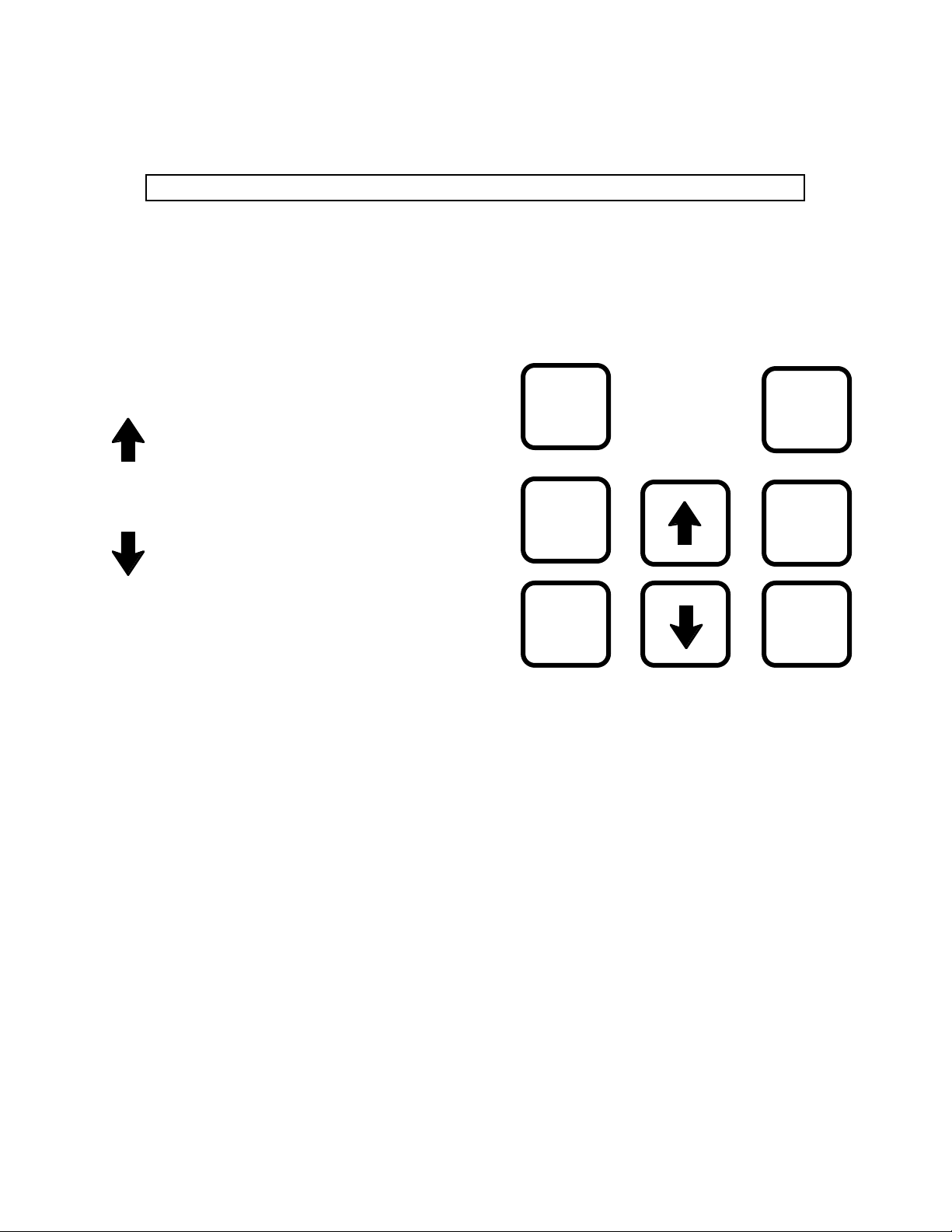
Figure 1 shows the control keys on the face of
the DV-II+ Viscometer. The following
describes the function of each key.
MOTOR
ON/OFF
AUTO
RANGE
UP ARROW
This key is used to scroll UP (in an increasing
value direction) through the available speed or
spindle tables.
SET
SPEED
SELECT
SPINDLE
DOWN ARROW
This key is used to scroll DOWN (in a decreasing value direction) through the available speed
or spindle tables.
SELECT
DISPLAY
MOTOR ON/OFF
Turns the motor ON or OFF.
Figure 1
SET SPEED
Causes the DV-II+ to begin running at the currently selected speed. This key is used for Time to
Torque and Timed Stop Tests (see Section II.10 - Timed Modes for Viscosity Measurement).
SELECT DISPLAY
Selects the data parameter to be displayed:
% Viscometer Torque (%)
cP Viscosity (cP or mPa.s)
SS Shear Stress (dynes/cm2 or Newtons/m2)
SR Shear Rate (1/sec)
Note: Pressing and holding the Select Display key during power on will enable the
temperature display for units of either °C or °F (see page 12).
AUTO RANGE
Presents the maximum (100% torque) viscosity attainable using the selected spindle at the current
viscometer spindle speed. This feature is functional when the motor is running.
PRINT
Note: Pressing and holding the Auto Range key during power on will enable the
display to be selected for either CGS or SI units of measurement (see page 11).
- 5 -
Page 6
SELECT SPINDLE
Initiates spindle selection on the first press and then selects the currently scrolled-to spindle when
pressed a second time. This key is used for Time to Torque and Timed Stop Tests (see Section II.10
- Timed Modes for Viscosity Measurement).
PRINT
Selects printing and non-printing modes when a printer is attached.
II. GETTING STARTED
II.1 Autozero
Before readings may be taken, the Viscometer must be Autozeroed. This action is performed each
time the power switch is turned on. The display window on the Viscometer will guide you through
the procedure as follows:
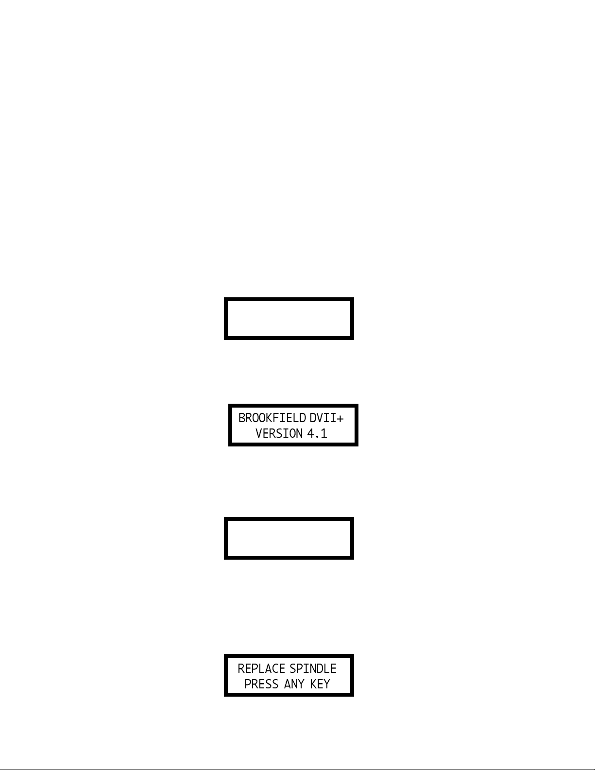
Turn the power switch (located on the rear panel) to the ON position. This will result in the following
screen display:
BROOKFIELD DVII+
RV VISCOMETER
Figure 2
After a few seconds, the following screen appears:
Figure 3
No key press is required at this point. After a short time, the display will clear and the following
will be displayed:
REMOVE SPINDLE
PRESS ANY KEY
Figure 4
After removing the spindle and pressing any key, the DV-II+ begins its Autozero. The screen will
flash "Autozeroing."
After approximately 15 seconds, the display shows “Replace Spindle Press Any Key”.
Figure 5
- 6 -
Page 7

Pressing any key at this point results in the display of the DV-II+ default screen:
Figure 6
The display will vary slightly depending upon the status of temperature and last spindle entered.
II.2 Spindle Selection
LVDV-II+ Viscometers are provided with a set of four spindles and a narrow guardleg; RVDV-II+
Viscometers come with a set of seven spindles and a wider guardleg; HADV-II+ and HBDV-II+
Viscometers come with a set of seven spindles and no guardleg. (See Appendix E for more
information on the guardleg.)
The spindles are attached to the viscometer by screwing them to the lower shaft. Note that the
spindles have a left-hand thread. The lower shaft should be held in one hand and the spindle screwed
to the left. The face of the spindle nut and the matching surface on the lower shaft should be smooth
and clean to prevent eccentric rotation of the spindle. Spindles can be identified by the number on
the side of the spindle coupling nut.
The DV-II+ must have a Spindle Entry Code number to calculate Viscosity, Shear Rate and Shear
Stress values. The DV-II+ memory contains parameters for all standard Brookfield spindles and the
two digit entry code for each spindle (the complete list of entry codes may be found in Appendix D).
Note: The DV-II+ will remember the Spindle Entry Code which was in use when the power was
turned off.
Pressing the SELECT SPINDLE key will cause the character S on the top line of the display to begin
to blink . It will blink for about three seconds. If the UP or DOWN Arrow keys are pressed (while
S is blinking) the two character spindle value to the right of the S character will begin to change (in
either an increasing or decreasing direction depending upon which Arrow key is pressed) for each
press of the key. If the Arrow key is pressed and held, the display will scroll through the spindle codes
for as long as the Arrow key is depressed. When it reaches the last item in the list (either at the top
or bottom of the list) the spindle code displayed will “roll-over” to either the first or last spindle code
and the scroll action will continue.
When the desired spindle code is displayed, release the Arrow key to halt further scrolling. Press
the SELECT SPINDLE key once again. This will cause the S character to cease blinking and the
new spindle code will be accepted for use in viscometer calculations.
Note: You have approximately three seconds in which to press the SELECT SPINDLE key
before the blinking stops. If you fail to press the SELECT SPINDLE key before the
blinking stops you will have to repeat the above steps and re-select the desired spindle.
The DV-II+ will begin to calculate using the new spindle parameters as soon as the SELECT
SPINDLE key is pressed the second time.
Note: The number 99 spindle is for use with special spindles when using Brookfield’s
DVGATHER+ or WINGATHER computer programs. Refer to the DVGATHER+ or
WINGATHER manuals for further information on using “99” spindles.
- 7 -
Page 8
The DV-II+ may also be programmed at Brookfield Engineering for “special” user spindles. These
“special” spindles will show up on the spindle scroll list starting with designation “AA” and
continuing through “AZ”. Contact Brookfield Engineering regarding your needs for special
spindles.
II.3 Speed Selection & Setting
There are 18 speeds programmed into the standard DV-II+. These speeds correspond to the standard
LVT, RVT, HAT, HBT, LVF and RVF dial models. If the DV-II
at speed 0.0. It will then scroll up through the LV speeds, pass through speed 0.0 again, and then scroll
up through the RV speeds at which point it will pass through speed 0.0 again and will then repeat the
above sequence. If the DV-II
The DV-II+ will start at 0.0 and scroll through the RV speeds, pass through 0.0 again and then scroll
through the LV speeds until it again reaches speed 0.0. The speed sets are described in Table 1.
+ is an RV (HA and HB) “type”, the inverse of the above will occur.
+ is an LV, the speed set will start
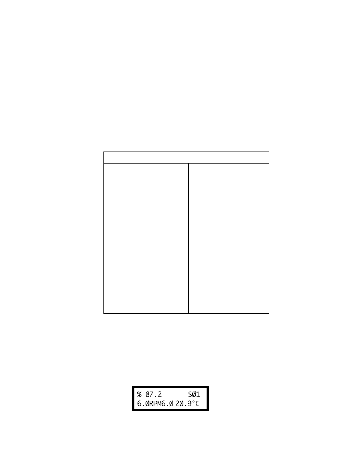
Table 1
DV-II+ Speed Sets
LV Instruments RV/HA/HB Instruments
0.0 0.0
0.3 0.5
0.6 1.0
1.5 2.0
3.0 2.5
6.0 4.0
12.0 5.0
30.0 10.0
60.0 20.0
0.0 50.0
0.5 100.0
1.0 0.0
2.0 0.3
2.5 0.6
4.0 1.5
5.0 3.0
10.0 6.0
20.0 12.0
50.0 30.0
100.0 60.0
The DV-II+ may also be programmed with “special” speed sets. A list of special speed sets is
included in Appendix F. Please consult Brookfield Engineering or your local dealer/distributor for
any special speed requirements not addressed by the standard or special speed sets.
To select a Viscometer speed first press either the UP or DOWN arrow keys which will cause the
area to the right of RPM (on the bottom line) to display the currently selected speed. Figure 7 shows
the DV-II+ had been operating at 6.0 RPM, and the current selected speed is 6.0 RPM.
Figure 7
- 8 -
Page 9
If the Arrow key is pressed just once and then released, the characters RPM will blink for three
seconds, then will cease blinking resulting in no change to the speed entry.
Note: The speed selection process remembers the last value of scrolled-to speed so that the next
time you initiate a speed change (by pressing an Arrow key), the DV-II
scroll display from the last entered value.
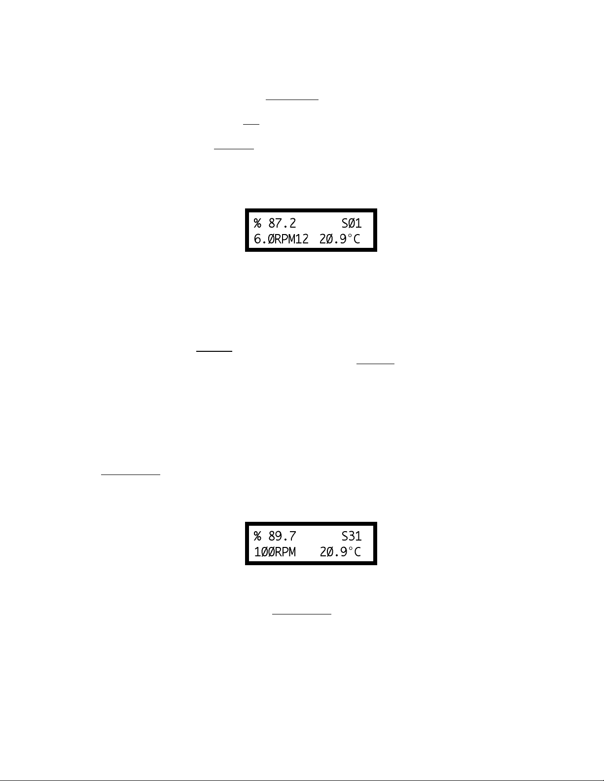
The last-scrolled-to speed does not necessarily have to be the same as the speed at which the DV-
II
+ is currently running. The user may operate at a given speed and pre-set the DV-II+ to the next
desired speed before that speed will be used. For example, if the DV-II+ is currently running at 6.0
RPM and was previously scrolled to 12 RPM, a single press of either Arrow key would result in the
Figure 8 screen display:
Figure 8
Pressing the SET SPEED key would cause the DV-II+ to begin running at 12 RPM.
If the user did not press the SET SPEED key, the DV-II+ would continue to run at its current speed
of 6 RPM. In fact, you may scroll to a new speed (12 RPM in this example) and press the SET SPEED
key at any future time (without further pressing an Arrow key) to immediately cause the DV-II+ to
run at the new speed. Pressing the Arrow key at any time reminds the operator of what was selected
for the next speed.
+ will begin its
If an Arrow key is pressed and held the DV-II+ will scroll up (or down) through the speed table.
When it reaches the last speed in the list (either at the top or bottom of the list) the speed displayed
will ”roll-over” to either the first or last speed in the table and the scroll action will continue.
When the required speed is displayed, release the Arrow key to halt further scrolling. You have
approximately two seconds (before the blinking RPM stops) in which to press the SET SPEED key
to immediately begin rotation at the new speed.
Pressing the MOTOR ON/OFF key stops the Viscometer spindle rotation. Pressing this key sets
the DV-II+ to 0.0 RPM and causes the screen display to change as shown in Figure 9:
Figure 9
Pressing the MOTOR ON/OFF again immediately starts the DV-II+ running at the last scrolledto-speed. If you had been running at 12 RPM, pressed MOTOR ON/OFF and then re-started the
DV-II+ by pressing MOTOR ON/OFF once again, you would again be running at 12 RPM.
However, if while the motor was off you had scrolled to a new speed of 0.5 RPM, pressing the
MOTOR ON/OFF key would start the DV-II+ running at 0.5 RPM.
Note: During both spindle or speed selection and scrolling operations, the DV-II+ will continue
to calculate and display Viscometer data as selected.
- 9 -
Page 10
II.4 Display Selection
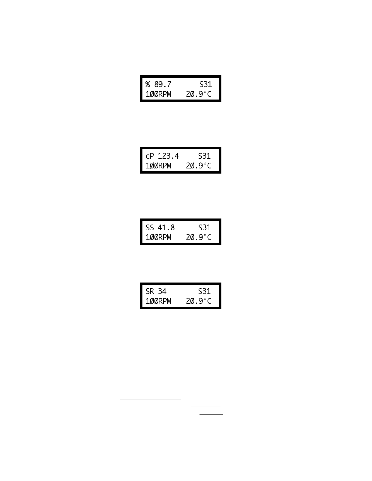
Viscometric data (%, cP, SS, SR) is displayed on the left side of the top line. You may “step” through
the four display options by pressing the SELECT DISPLAY key. For example, if the DV-II+ were
currently displaying % (Torque) as shown in Figure 10:
Figure 10
The first press of the SELECT DISPLAY key would display viscosity in cP (or mPa.s), see Figure
11:
Figure 11
The next press of the SELECT DISPLAY key would display SS (Shear Stress) in Dynes/Cm2 (or
Newtons/m2).
Figure 12
The next press of the SELECT DISPLAY key would display SR (Shear Rate) in 1/Sec.
Figure 13
One more press of the SELECT DISPLAY key would result in a re-display of the % (Torque)
screen, as shown in Figure 10.
Note: You may step through the display at any time. This will not interrupt any Viscometer
calculations that are in progress.
II.5 Autorange and CGS or SI Units Selection
The AUTO RANGE key allows you to determine the maximum calculated viscosity (full scale
reading) possible with the current spindle/speed setting. Pressing the key at any time will cause the
current viscosity display to change and show that maximum viscosity. The screen area formerly
displaying temperature display will now display a flashing “%100.0” to indicate this special
condition. This maximum viscosity and flashing %100.0 value will be displayed for as long as the
AUTO RANGE key is depressed. Figure 14 shows the AUTO RANGE function for the situation
where the No. 1 LV spindle is rotating at 60 rpm. The full scale range is 100.0 cP (or 100.0 mPa.s).
- 10 -
Page 11
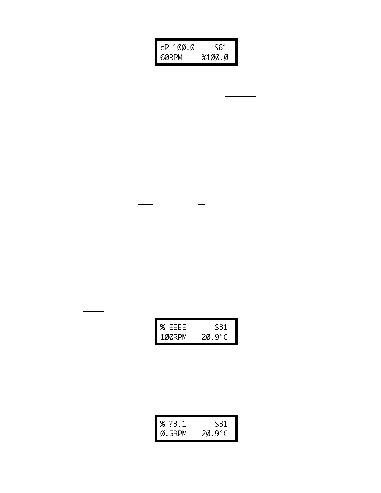
Figure 14
Note: 1. If the MOTOR is OFF or the RPM is 0.0, the maximum viscosity displayed will be 0.0
cP (or 0.0 mPa.s).
2. While the Viscometer is in the Auto Range mode, any data sent to an attached printer or
computer reflects the displayed values (i.e. Auto Range values).
Pressing and holding the AUTO RANGE key during power on will enable the selectable display to
be read in either CGS or SI units. To change the unit format:
1. Turn the power off.
2. Press and hold the AUTO RANGE key and turn the power ON.
The DV-II+ will retain the unit selection when the viscometer is turned OFF.
CGS SI
Viscosity cP mPa.s
Shear Stress dyne/cm
Shear Rate sec
-1
2
N/m
sec
2
-1
Torque % %
DV-II+ Viscometers without this function can be updated. Contact Brookfield or your local
Brookfield dealer for this service.
II.6 Out of Range
The DV-II+ gives indications for out of specification or out-of-range operation. When % (Torque)
readings exceed 100.0 % (over-range), the display changes to that shown in Figure 15:
Figure 15
EEEE will also appear when viscosity or shear stress are over range. You must change either speed
or spindle to correct this condition. If you operate at spindle speeds that produce % (Torque) below
10.0 % (under-range), the DV-II+ displays % (Torque), cP (Viscosity) and SS (Shear Stress)
preceded by a “?” as shown in Figure 16:
Figure 16
- 11 -
Page 12
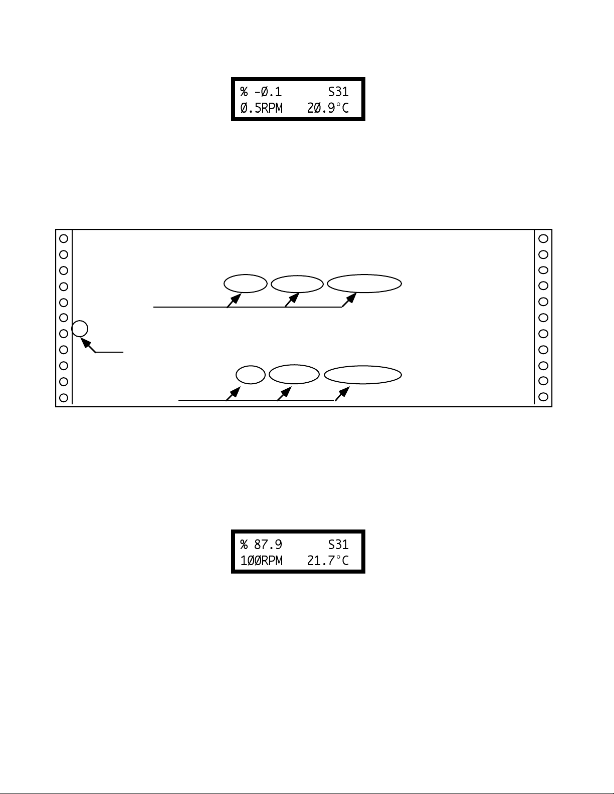
Negative % (Torque) will be displayed as shown in Figure 17:
Figure 17
cP (Viscosity) and SS (Shear Stress) values will be displayed as "- - - -" when the % (Torque) is
below zero.
Figure 18 is an example of the printed output of each of the above conditions.
RPM=50 MD=RV SPDL=29 %=51.4 cP=10280 D/CM2=1285 1/SEC=12.5 T=25.5C
Normal Print String
RPM=50 MD=RV SPDL=29 %=EEEE cP=EEEE D/CM2=EEEE 1/SEC=12.5 T=25.5C
Over-Range
?RPM=50 MD=RV SPDL=29 %=5.2 cP=1040 D/CM2=130 1/SEC=12.5 T=25.5C
Under-Range
RPM=50 MD=RV SPDL=29 %=-0.1 cP=---- D/CM2=---- 1/SEC=0.0 T=25.5C
Negative Torque
Figure 18
II.7 Temperature Display
The DV-II+ will display the temperature measured by its RTD temperature probe. Temperature may
be displayed in either ˚C (Centigrade) or ˚F (Fahrenheit) units depending upon the start-up
operations. If the DV-II+ is started normally, the default temperature display will be in ˚C
(Centigrade) units as shown in the Figure 19:
Figure 19
However, if you press and hold the SELECT DISPLAY key while turning on the DV-II+ the
temperature will be displayed in ˚F (Fahrenheit).
If you turn on the DV-II+ with the temperature probe disconnected, or remove the temperature probe
at any point after power-up, the display will indicate “- - - -°C”.
The four “dashes” indicate the absence of the probe. If you were displaying temperature in
Fahrenheit units the C would be displayed as an F.
- 12 -
Page 13
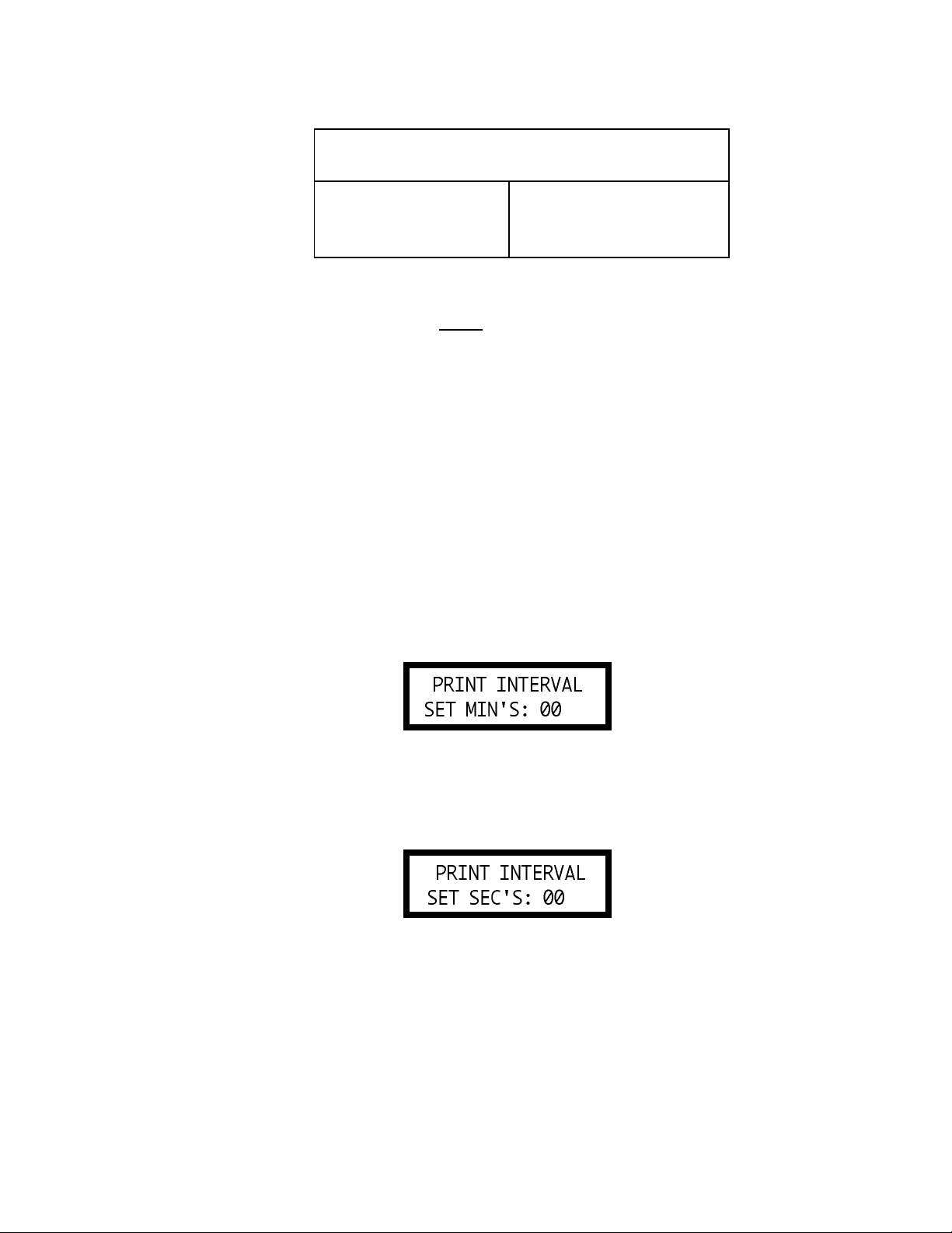
TABLE 2
Temperature Accuracies For
Digital Viscometer Model DV-II+
Temperature Range Temperature Accuracy
-100°C to +150°C ±1.0°C
+150°C to +300°C ±2.0°C
II.8 Printing
The DV-II+ will print data to an attached Serial printer. The printer must be attached to the rear panel
SERIAL AND ANALOG output connector. See Appendix G for the connection requirements.
The printer must be configured as follows:
Baud Rate 9600
Data Bits 8
Stop Bits 1
Parity None
Handshake None
Data may be printed in two ways:
1. Pressing the PRINT key once (for less than three (3) seconds) will result in the printing of one
standard print line.
2. If the PRINT key is pressed and held for more than three (3) seconds, the user will be presented
with the following screen:
Figure 20
Here the user is being asked to enter the time interval (in minutes and seconds) between
successive print strings. First, as depicted above the user is asked for the minutes entry and then
by pressing the print key the seconds entry as shown below:
Figure 21
The print interval maximum limits are 99 minutes and 59 seconds.
3. The method for entering the minutes and seconds values is accomplished by using the UP or
DOWN arrow keys. The PRINT key is used to advance from the minutes to seconds entries and
as the exit key after the user has input the seconds value.
Note: The value for minutes or seconds must be other than zero or you will not be able to exit
this mode.
- 13 -
Page 14

4. After the final press of the PRINT key, the DV-II+ will immediately begin sending out print
strings at the selected user print rate. To stop continuous printing, the user must press and hold
the PRINT key for three (3) seconds.
5. Only after the user again presses and holds the PRINT key for three (3) seconds will you be asked
for the minute and seconds entries. The previously selected values for time interval will be
retained in EEPROM so as to be available at the next power-up. Thus, if the user wishes to again
print continuously at the previous print interval, you will only have to press the PRINT key three
(3) times; once to accept the minutes entry; once to accept the seconds entry, and once to exit and
begin printing.
Note: On DV-II+ Viscometers with serial number DE27812 or higher, the RS-232 output
is automatically active after Auto Zero is executed.
The RS-232 output MUST be active (printing continuously) when using a computer
and DVGATHER+ software.
II.9 Operation
The following general procedure is used for making viscosity measurements. Brookfield recommends the use of a 600 ml Low Form Griffin type beaker when using LV/RV/HA/HB spindles in
order to obtain data that verifies proper calibration of the DV-II+ Viscometer (see Appendix E).
1. Mount the guardleg on the DV-II+ Viscometer (LV and RV series). Attach the spindle to the
lower shaft. Lift the shaft slightly, holding it firmly with one hand while screwing the spindle
on with the other (note left-hand thread). Avoid putting side thrust on the shaft.
2. Insert and center spindle in the test material until the fluid's level is at the immersion groove in
the spindle's shaft. With a disc-type spindle, it is sometimes necessary to tilt the instrument
slightly while immersing to avoid trapping air bubbles on its surface. (You may find it more
convenient to immerse the spindle in this fashion before attaching it to the Viscometer.)
3. To make a viscosity measurement, follow the instructions in II.2 and II.3. Allow time for the
indicated reading to stabilize. The time required for stabilization will depend on the speed at
which the Viscometer is running and the characteristics of the sample fluid. For maximum
accuracy, readings below 10% should be avoided.
4. Press the MOTOR ON/OFF key and turn the motor "OFF" when changing a spindle or changing
samples. Remove spindle before cleaning.
5. Interpretation of results and the instrument's use with non-Newtonian and thixotropic materials
is discussed in the booklet, "More Solutions to Sticky Problems", and in Appendix C, Variables
in Viscosity Measurements.
II.10 Timed Modes for Viscosity Measurement
The Timed Modes allow the viscometer user to implement Timed Stop and Time to Torque
capabilities with the DV-II+ Viscometer. These features will allow the user to set up the viscometer
(i.e. select spindle and speed) and then record readings for a fixed period of time (Timed Stop) or
until a set torque value is attained (Time to Torque). A series of menus will ask the user to input
minutes and seconds (Timed Stop) or % torque (Time to Torque) and will then begin timing when
the user presses the MOTOR ON/OFF key to ON. A message will be displayed showing time
remaining (or time elapsed) and the appropriate display item (viscosity or torque) will be updated
- 14 -
Page 15

continuously during the event. Upon completion, the viscometer will display a screen stating that
the test is complete and will also display the final recorded value for the viscosity in the first case,
and the time in minutes and seconds to reach the torque limit in the second case. Pressing the UP
or DOWN arrow keys will allow alternate data to be examined and pressing any other key (except
the PRINT key) will bring the user back to the default (normal) viscometer display with the motor
OFF. If the user wishes to run another test, repeat the above steps.
II.10.1 Set Up
1. The user must first select the temperature scale in °C or °F and the display unit option: CGS or
SI.
2. The user then selects (via the UP and DOWN arrows) the spindle speed.
Note: If 0.0 RPM is the selected speed setting (the default after executing AUTOZERO) the
timed modes can be executed; however, the results will be meaningless showing no
viscosity values.
3. Next, the user selects the spindle number corresponding to the spindle attached.
4. Now, the user presses the MOTOR ON/OFF key to ensure that the motor is OFF. Setting the
motor to the OFF condition sets up the viscometer for executing the Timed Modes.
5. The user presses the SET SPEED and SELECT SPINDLE keys simultaneously to enter either
of the timed test modes. Immediately the following screen appears:
Figure 22
6. The user presses either the UP or DOWN arrow key to select the test method of choice and is
immediately presented with the corresponding opening screen.
II.10.2 Timed Stop Implementation
1. After pressing the UP arrow key when in the display of Figure 23, the user is presented with the
following screen:
Figure 23
Using the UP and DOWN arrow keys, the user enters a value for the minutes portion of the time
to stop. This value can be as high as 99 minutes.
- 15 -
Page 16
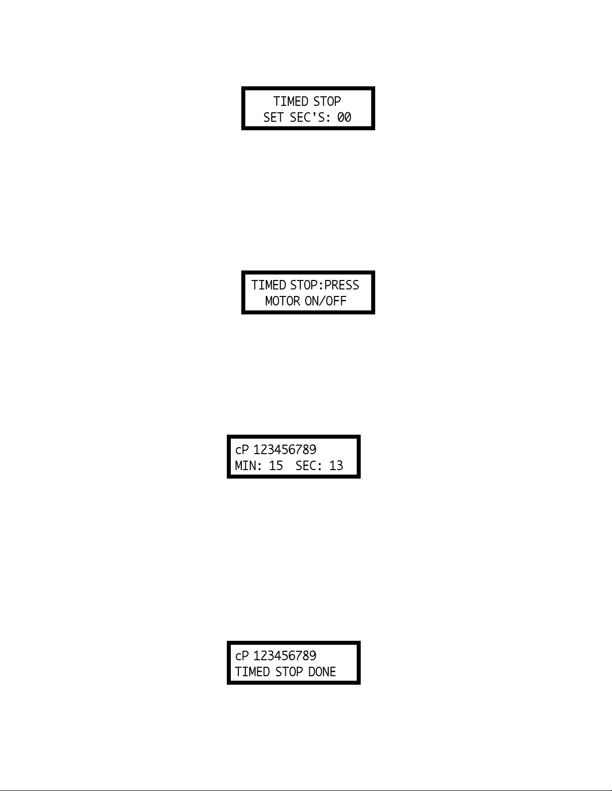
2. When satisfied, the user presses the SELECT SPINDLE key again to enter the seconds setting
display:
Figure 24
Using the UP and DOWN arrow keys, the user enters a value for the seconds portion of the time
to stop. This value will be between 0 and 59 seconds.
Note: The value for minutes or seconds must be other than zero or you will not be able to exit
this mode.
The user presses the SELECT SPINDLE key one more time to end his time input at which point
the viscometer will display the following screen:
Figure 25
3. At this point, the user need only press the MOTOR ON/OFF key to begin the timed stop
operation. Any other key will abort the process and the user will have to begin again by
simultaneously pressing the SET SPEED and SELECT SPINDLE keys.
4. We will assume that the user pressed the MOTOR ON/OFF key to ON and is now presented with
the following screen for the duration of the timed run:
Figure 26
Note:
1. When this mode has begun, a press of the MOTOR ON/OFF key will interrupt the Timed
Stop sequence and return the user to normal operation.
2. Also see Comments on Print Mode Operation in Section II.10.4 for a description of print
options available on DV-II+ during the Timed Stop run.
The seconds display will decrement from 59 to zero (0) in one (1) second intervals. When seconds
reaches zero (0), the minutes value will decrement by one (1) minute. This will continue until all
of the time has elapsed at which point the viscometer will display the following screen:
Figure 27
- 16 -
Page 17

At this point, the viscometer will stop the motor and continue to display this screen until any key
except the UP or DOWN arrow key or the PRINT key is pressed. The user presses the UP or
DOWN arrow keys to view the Torque and Speed that were current at the Timed Stop completion.
This display would appear as follows:
Figure 28
The display will switch between that of Figures 27 and 28 for each press of either the UP or
DOWN arrow key. Pressing any key except the UP or DOWN arrow keys or PRINT key will
cause the viscometer to exit the Timed Stop mode and resume normal operation.
Note:
1. The user can press the PRINT key while in either of these two screens (Figures 27 and 28)
to send one standard print string to the attached printer as many times as the user presses
the PRINT key. Pressing any other key will exit this mode and return the viscometer to
normal operation.
2. For the Timed Stop method, the DV-II+ Viscometer will retain the last value for the time
interval in EEPROM so that it will become the default the next time the user elects to use
this method.
II.10.3 Time to Torque Implementation
1. After pressing the DOWN arrow key when in the display of Figure 22, the user is presented
with the following screen:
Figure 29
Using the UP and DOWN arrow keys, the user enters a value for the torque level which the
viscometer must achieve. This value can be as high as 99%.
Note: The value for torque must be other than zero or you will not be able to exit this mode.
2. The user presses the SELECT SPINDLE key one more time to end the torque input at which
point the viscometer will display the following screen:
Figure 30
The time to torque value can be as high as 99 minutes and 59 seconds.
- 17 -
Page 18

3. At this point, the user need only press the MOTOR ON/OFF key to begin the timed torque
operation. Any other key will abort the process and he will have to begin again by simultaneously
pressing the SET SPEED and SELECT SPINDLE keys.
4. We will assume that the user pressed the MOTOR ON/OFF key to ON and is now presented with
the following display for the duration of the timed torque run:
Figure 31
Note:
1. When this mode has begun, a press of the MOTOR ON/OFF key will interrupt the time
to torque operation and return the user to normal operation.
2. Also, see Comments on Print Mode Operation in Section II.10.4 for a description of
print options available on DV-II+ during the Time to Torque run.
The seconds display will increment from zero (0) to 59 in one (1) second intervals and the current
value of the viscometer torque will be updated continuously. When seconds reach 59, the minutes
value will increment by one (1) minute. This will continue until the user selected torque value
is attained at which point the viscometer will display the following screen:
Figure 32
At this point, the viscometer will stop the motor and continue to display this screen until the user
presses the UP or DOWN arrow keys or the PRINT key to view the viscosity that was current
at the Timed Torque completion. The display would appear as follows:
Figure 33
The display will switch between that of Figures 32 and 33 for each press of either the UP or
DOWN arrow key. Pressing any key except the UP or DOWN arrow key or the PRINT key will
cause the viscometer to exit the Timed Torque mode and resume normal operation.
Note:
1. The user can press the PRINT key while in either of these two screens (Figures 32 and 33)
to send one standard print string to the attached printer as many times as the user presses
the PRINT key. Pressing any other key will exit this mode and return the viscometer to
normal operation.
2. For the Time to Torque method, the DV-II+ Viscometer will retain the last entered torque
in EEPROM for use when the user elects to perform a time to torque test again.
- 18 -
Page 19

II.10.4 Comments on Print Mode Operation
The high-speed-print jumper (between pins four (4) and nine (9) on the RS-232 plug found on the
Brookfield PC Cable - Part No. DVP-80) is used exclusively with Brookfield’s DVGATHER+ and
WINGATHER software. This jumper if in place will override all of the above and will immediately
place the DV-II+ into the maximum print speed mode. When in this high speed print mode, the ability
to access either of the timed modes from the front panel will not be allowed and PRINT key presses
will be ignored. When the user returns to stand-alone operation with a printer, you will remove the
Brookfield PC cable (with the high-speed jumper) and replace it with the Brookfield Printer Cable
(Part No. DVP-81) or any standard serial printer cable which will re-enable the print modes described
above.
Additionally, the DV-II+ user can set up a desired print interval time, then set the viscometer to the
continuous print mode and finally initiate either of the timed modes of operation. While setting up
timed mode parameters, continuous print operation will cease. However, upon starting the timed
operation, the DV-II+ will output an initial data string to the printer and then continue printing data
strings (at the user defined time interval) for the duration of the timed run. At the end of the timed
run, continuous printing will again be disabled and the user may print single strings (of the final data
point) at your option until exiting the timed mode. Upon returning to the default operation mode,
continuous printing will again resume at the user selected time interval. In a similar manner, if the
user is in the one-print-per-key-press mode when entering the timed mode of operation, you will be
able to print data strings at any time during the timed mode by pressing the PRINT key when output
is desired.
- 19 -
Page 20

APPENDIX A - Cone/Plate Viscometer Set-Up
The Cone/Plate version of the DV-II+ Viscometer uses the same operating instruction procedures as
described in this manual. However, the gap between the cone and the plate must be mechanically
adjusted before measurements are made. This is done by moving the plate (built into the sample cup,
CP-44Y) up towards the cone until two small pins (one in the cone, the second mounted on the plate)
contact, and then separating (lowering) the plate 0.0005inch (0.013mm).
Note that the Cone/Plate Viscometer REQUIRES the use of a good circulating temperature bath
controlling temperature to within (
cup.
The following example assumes that the C/P Viscometer is set up on the Model A stand, and has been
zeroed with no cone attached. Cone CP-40 is used in the example. The water bath is on, set at the proper
temperature (the adjustment procedure must be done at test temperature) and is connected to the sample
cup. The Viscometer should be set at 0 rpm with MOTOR ON.
Connect sample cup ports to the water bath inlet and outlet, and set the bath to the test temperature. Allow
enough time for the bath to reach the test temperature (Figure A1).
+/-) 0.1 °C. The bath is connected to the ports on the CP-44Y sample
Adjusting
Ring
Adjustment Ring
Cup
Cup
Outlet
Outlet
Bath
Bath
Bath
Outlet
Outlet
PUMP
OUTLET
PUMP
INLET
Bath
Inlet
Inlet
Water
Bath
Cup
Cup
Inlet
Inlet
Sample
Sample
Cup
Cup
Figure A1
Remove sample cup and attach the cone to the Viscometer (Note: left hand threads), using the spindle
wrench to hold the Viscometer shaft (Figure A2). Note: Lift up gently on the spindle wrench.
- 20 -
Page 21

These Surfaces
These surfaes
Must be Clean!
must be clean!!!
Spindle Wrench
Spindle Wrench
Cone
Cone
Figure A2
Attach the sample cup and swing the clip under the cup to secure it in place. Take care to avoid hitting
the cone with the cup (Figure A3). Note: Do not add test sample during the gap setting procedure.
Do Not Hit
Do Not Hit
the CONE
the CONE
with the CUP!!!
with the CUP!
Figure A3
Set and start the DV-II+ running at 10 rpm. Choose to display "%" information by pressing SELECT
DISPLAY (see Section II.4 for details).
If the display reading jumps to 0.4% of scale (or higher), or will not settle to zero (indicating that the pins
on the cone and cup are hitting), unscrew the adjustment ring by turning it to the left (clockwise as you
look down on the instrument) until the reading settles at 0 (Figure A4).
- 21 -
Page 22

Adjusting Ring
Adjustment Ring
Index Mark
Index Mark
Turn Adjustment Ring Clockwise Until
the % Torque Display is Stable at 0.0%
Turn Adjusting Ring clockwise until the % torque
Figure A4
display is stable at 0.0%
Turn the adjustment ring to the right (counterclockwise as you look down on the instrument) in small
increments (one or two divisions of the ring) while watching the Viscometer display. Remember that
you are trying to lower the cone so that the pin in the cone touches the pin in the cup. Once you have
found this hit point, you can "back off" to create the desired gap between cone and cup. You must wait
at least 6 seconds between movements of the ring. Turn the adjusting ring until the display reading jumps
from 0 to 0.5% (HB Models) or from 0 to 1.0% (LV, RV and HA Models). This is the HIT POINT.
The cup may have to be adjusted up and down several times before this deflection is satisfactorily
reached. LV series DV-II+s will be the most sensitive (Figure A5).
Index Mark
Index Mark
Adjusting Ring
Adjustment Ring
Figure A5
- 22 -
Turn Adjustment Ring Counterclockwise
in Small Increments
Page 23

When you are satisfied the pins are just hitting (by observing acceptable % readings), make a pencil mark
on the adjustment ring directly under the index mark on the pivot housing (Figure A6).
Index
Mark
Index Mark
Adjustment
Adjusting Ring
Ring
Make a Pencil Mark
Directly Under the
Make a pencil
mark directly
under the
index mark
Index Mark
Figure A6
Turn the adjustment ring to the left (clockwise as you look down on the instrument) exactly the width
of one division from the pencil mark you have just made. This will separate the pins by 0.0005" (0.013
mm). Allowing the pins to touch constantly may cause wear and damage to the cone, cup and instrument.
The Viscometer is now mechanically set and ready for sample measurement (Figure A7).
Index Mark
Index Mark
Adjusting Ring
Adjustment
Ring
Figure A7
- 23 -
One Scale
One Scale
Division
Division
Turn Adjustment Ring Clockwise a
Distance Equal to One Scale Division
Page 24

Each of the five available cones has a specific sample volume, as shown in Table A1. Note that the
correct amount of sample fluid should cover the cone face and back up over the edge less than 1mm as
shown in (Figure A8).
Less than
Less Than
1 mm
Cone
Cone
Cup
Cup
Sample
Sample
1 mm
Figure A8
Notes: a) The cup may be removed without resetting the gap.
b) Remove the spindle from the viscometer when you clean it.
c) Reset the hit point every time the spindle is attached.
Table A1
Cone Sample Volume Cone Angle
CP-40 0.5 ml 0.8°
CP-41 2.0 ml 3.0°
CP-42 1.0 ml 1.565°
CP-51 0.5 ml 1.565°
CP-52 0.5 ml 3.0°
Calibration Procedure for Cone/Plate Viscometers:
1) Follow the procedures outlined in Appendix A for mechanically adjusting the setting of the cone
to the plate.
2) Refer to Table A1, and determine the correct sample volume required for the spindle to be
utilized.
3) Select a viscosity standard fluid that will give viscosity readings between 10% and 100% of full
scale range. Refer to Appendix B for viscosity ranges of cone spindles. Consult with Brookfield
or an authorized dealer to determine which fluid is appropriate.
- 24 -
Page 25

It is best to use a viscosity standard fluid that will be close to the maximum viscosity for a given
cone spindle/speed combination.
Example: LVDV-II+ Viscometer, Cone CP-42, Fluid 10
Having a viscosity of 9.7 cP at 25°C
At 60 RPM, the full scale viscosity range is 10.0 cP. Thus, the Viscometer reading should be
97% torque and 9.7 cP viscosity ± 0.197 (closer to ±0.2) cP. The accuracy is a combination of
Viscometer and fluid tolerance (refer to Interpretation of Calibration Test Results).
4) With the viscometer stopped, remove the sample cup and place the viscosity standard fluid into
the cup, waiting 10 minutes for temperature equilibrium.
5) Connect the sample cup to the Viscometer. Allow 10 minutes for temperature to reach
equilibrium.
6) Measure the viscosity and record the Viscometer reading in both % torque and centipoise (cP).
Note: The spindle must rotate at least five (5) times before a viscosity reading is taken.
- 25 -
Page 26

Appendix B - Viscosity Ranges
LV(#1-4) and RV,HA,HB(#1-7) Viscometers
Viscosity Range (cP)
Viscometer Minimum Maximum
LVDV-II+ 15 2,000,000
RVDV-II+ 100 13,300,000
HADV-II+ 200 26,600,000
HBDV-II+ 800 106,400,000
Small Sample Adapter and Thermosel
SSA & T-Sel Shear Rate Viscosity (cP)
Spindle (1/SEC) LVDV-II+
16 0 - 29.0 120 - 400,000
18 0 - 132.0 3 - 10,000
25 0 - 22.0 480 - 1,600,000
31 0 - 34.0 30 - 100,000
34 0 - 28.0 60 - 200,000
81 0 - 129.0 3.4 - 10,000
82 0 - 129.0 3.4 - 10,000
83 0 - 129.0 11.3 - 37,898
Viscosity (cP)
SSA/T-Sel Shear Rate
Spindle (1/SEC) RVDV-II+ HADV-II+ HBDV-II+
14 0 - 40.0 1,250 - 4,165,000 2,500 - 8,330,000 10,000 - 33,360,000
15 0 - 48.0 500 - 1,660,000 1,000 - 3,320,000 4,000 - 13,280,000
21 0 - 93.0 50 - 167,000 100 - 334,000 400 - 1,336,000
27 0 - 34.0 250 - 830,000 500 - 1,660,000 2,000 - 6,640,000
28 0 - 28.0 500 - 1,660,000 1,000 - 3,320,000 4,000 - 13,280,000
29 0 - 25.0 1,000 - 3,330,000 2,000 - 6,660,000 8,000 - 26,640,000
81 0 - 129.0 36.5 - 10,000 73.0 - 10,000 292.0 - 10,000
82 0 - 129.0 36.5 - 10,000 73.0 - 10,000 292.0 - 10,000
83 0 - 129.0 121.3 - 50,000 242.6 - 50,000 970.4 - 50,000
UL Adapter
Viscosity (cP)
UL Shear Rate
Spindle (1/SEC) LVDV-II+ RVDV-II+ HADV-II+ HBDV-II+
YULA-15 or 15Z 0 - 122.4 1.0 - 2,000 6.4 - 2,000 12.8 - 2,000 51.2 - 2,000
ULA-DIN-Y 0 - 129.1 1.0 - 3,800 10.6 - 5,000 21.2 - 5,000 84.8 - 2,000
- 26 -
Page 27

DIN Adapter Accessory
Viscosity (cP)
DAA Shear Rate
Spindle (1/SEC) LVDV-II+ RVDV-II+ HADV-II+ HBDV-II+
85 0 - 129 1.2 - 3,812 12.2 - 5,000 24.4 - 5,000 97.6 - 5,000
86 0 - 129 3.4 - 10,000 36.5 - 10,000 73.0 - 10,000 292.0 - 10,000
87 0 - 129 11.3 - 37,898 121.3 - 50,000 242.6 - 50,000 970.4 - 50,000
Spiral Adapter
Viscosity (cP)
Spiral Shear Rate
Spindle (1/SEC) LVDV-II+ RVDV-II+ HADV-II+ HBDV-II+
SA-70 .677 - 67.7 98.4 - 98,416 1,050- 1,050,000 2,100 - 2,100,000 8,400 - 8,400,000
(1 - 100 RPM)
The maximum viscosity ranges correspond to a spiral spindle rotational speed of 1.0 RPM. Lower
spindle speeds are possible but the pumping action within the spiral chamber may not be sufficient to
provide meaningful vicosity data.
Cone/Plate Viscometer
Cone Shear Rate
Viscosity (cP)
Spindle (1/SEC) LVDV-II+C/P RVDV-II+C/P HADV-II+C/P HBDV-II+C/P
CP-40 0.0 -750 0.30 - 1,028 3.3 - 10,900 6.6 - 21,800 26.2 - 87,200
CP-41 0.0 -200 1.15 - 3,840 12.3 - 41,000 24.6 - 82,000 98.4 - 328,000
CP-42 0.0 -384 0.60 - 2,000 6.4 - 21,300 12.8 - 42,600 51.2 - 170,400
CP-51 0.0 -384 4.85 - 16,180 51.2 - 171,000 102.4 - 342,000 409.6 - 1,368,000
CP-52 0.0 -200 9.33 - 31,100 98.3 - 328,000 196.6 - 654,000 786.4 - 2,624,000
Helipath with T-Bar Spindles
T-Bar
Viscosity (cP)
Spindle LVDV-II+ RVDV-II+ HADV-II+ HBDV-II+
T-A 156 - 62,400 2,000 - 400,000 4,000 - 800,000 16,000 - 3,200,000
T-B 312 - 124,800 4,000 - 800,000 8,000 - 1,600,000 32,000 - 6,400,000
T-C 780 - 312,000 10,000 - 2,000,000 20,000 - 4,000,000 80,000 - 16,000,000
T-D 1,560 - 624,000 20,000 - 4,000,000 40,000 - 8,000,000 160,000 - 32,000,000
T-E 3,900 - 1,560,000 50,000 -10,000,000 100,000 - 20,000,000 400,000 - 80,000,000
T-F 7,800 - 3,120,000 100,000 -20,000,000 200,000 - 40,000,000 800,000 -160,000,000
In taking viscosity measurements with the DV-II+ Viscometer there are two considerations which
pertain to the low viscosity limit of effective measurement.
1) Viscosity measurements should be accepted within the equivalent % Torque Range from
10% to 100% for any combination of spindle/speed rotation.
2) Viscosity measurements should be taken under laminar flow conditions, not under turbulent
flow conditions.
The first consideration has to do with the precision of the instrument. All DV-II+ Viscometers have a
full scale range precision of (+/-) 1% of any spindle/speed rotation. We discourage taking readings below
- 27 -
Page 28

10% of range because the potential viscosity error of (+/-) 1% is a relatively high number compared to
the instrument reading.
The second consideration involves the mechanics of fluid flow. All rheological measurements of fluid
flow properties should be made under laminar flow conditions. Laminar flow is flow wherein all particle
movement is in layers directed by the shearing force. For rotational systems, this means all fluid
movement must be circumferential. When the inertial forces on the fluid become too great, the fluid can
break into turbulent flow wherein the movement of fluid particles becomes random and the flow can not
be analyzed with standard math models. This turbulence creates a falsely high Viscometer reading with
the degree of non-linear increase in reading being directly related to the degree of turbulence in the fluid.
For the following geometries, we have found that an approximate transition point to turbulent flow
occurs:
1) No. 1 LV Spindle: 15 cP at 60 RPM
2) No. 1 RV Spindle: 100 cP at 50 RPM
3) UL Adapter: 0.85 cP at 60 RPM
Turbulent conditions will exist in these situations whenever the RPM/cP ratio exceeds the values listed
above.
- 28 -
Page 29

Appendix C - Variables in Viscosity Measurements
As with any instrument measurement, there are variables that can affect a Viscometer measurement.
These variables may be related to the instrument (Viscometer), or the test fluid. Variables related to the
test fluid deal with the rheological properties of the fluid, while instrument variables would include the
Viscometer design and the spindle geometry system utilized.
Rheological Properties
Fluids have different rheological characteristics that can be described by Viscometer measurements. We
can then work with these fluids to suit our lab or process conditions.
There are two categories of fluids:
Newtonian - These fluids have the same viscosity at different Shear Rates (different
RPMs) and are called Newtonian over the Shear Rate range they are
measured.
Non-Newtonian - These fluids have different viscosities at different shear rates (different
RPMs). They fall into two groups:
1) Time Independent non-Newtonian
2) Time Dependent non-Newtonian
The time dependency is the time they are held at a given Shear Rate (RPM). They are non-Newtonian,
and when you change the Viscometer spindle speed, you get a different viscosity.
Time Independent
Pseudoplastic - A pseudoplastic material displays a decrease in viscosity with an increase in
shear rate, and is also known as “shear thinning”. If you take Viscometer
readings from a low to a high RPM and then back to the low RPM, and the
readings fall upon themselves, the material is time independent pseudoplastic
and shear thinning.
Time Dependent
Thixotropic - A thixotropic material has decreasing viscosity under constant shear rate. If
you set a Viscometer at a constant speed recording cP values over time and
find that the cP values decrease with time, the material is thixotropic.
Brookfield publication, “More Solutions to Sticky Problems” includes a more detailed discussion of
rheological properties and non-Newtonian behavior.
Viscometer Related Variables
Most fluid viscosities are found to be non-Newtonian. They are dependent on Shear Rate and the spindle
geometry conditions. The specifications of the Viscometer spindle and chamber geometry will affect
the viscosity readings. If one reading is taken at 2.5 rpm, and a second at 50 rpm, the two cP values
produced will be different because the readings were made at different shear rates. The faster the spindle
speed, the higher the shear rate.
The shear rate of a given measurement is determined by: the rotational speed of the spindle, the size and
shape of the spindle, the size and shape of the container used and therefore the distance between the
- 29 -
Page 30

container wall and the spindle surface.
A repeatable viscosity test should control or specify the following:
1) Test temperature
2) Sample container size (or spindle/chamber geometry)
3) Sample volume
4) Viscometer model
5) Spindle used (if using LVDV-II+ (#1-4) or RVDV-II+ (#1-7) attach the guard leg)
6) Test speed or speeds (or the shear rate)
7) Length of time or number of spindle revolutions to record viscosity.
- 30 -
Page 31

Appendix D - Spindle and Model Codes
Each spindle has a two digit entry code which is entered via the keypad on the DV-II+. The entry code
allows the DV-II+ to calculate Viscosity, Shear Rate and Shear Stress values.
Each spindle has two constants which are used in these calculations. The Spindle Multiplier Constant
(SMC) used for viscosity and shear stress calculations, and the Shear Rate Constant (SRC), used for
shear rate and shear stress calculations. Note that where SRC = 0, no shear rate/shear stress calculations
are done and the data displayed is zero (0) for these functions.
Table D1
SPINDLE ENTRY CODE SMC SRC
RV1 01 1 0
RV2 02 4 0
RV3 03 10 0
RV4 04 20 0
RV5 05 40 0
RV6 06 100 0
RV7 07 400 0
HA1 01 1 0
HA2 02 4 0
HA3 03 10 0
HA4 04 20 0
HA5 05 40 0
HA6 06 100 0
HA7 07 400 0
HB1 01 1 0
HB2 02 4 0
HB3 03 10 0
HB4 04 20 0
HB5 05 40 0
HB6 06 100 0
HB7 07 400 0
LV1 61 6.4 0
LV2 62 32 0
LV3 63 128 0
LV4 64 640 0
LV5 65 1280 0
Spiral 70 105 0.677
T-A 91 20 0
T-B 92 40 0
T-C 93 100 0
T-D 94 200 0
T-E 95 500 0
T-F 96 1000 0
ULA 00 0.64 1.223
TSEL-DIN-81 81 3.7 1.29
SSA-DIN-82 82 3.75 1.29
SSA-DIN-83 83 12.09 1.29
ULA-DIN-85 85 1.22 1.29
ULA-DIN-86 86 3.65 1.29
ULA-DIN-87 87 12.13 1.29
- 31 -
Page 32

Table D1 (continued)
SPINDLE ENTRY CODE SMC SRC
SC4-14 14 125 0.4
SC4-15 15 50 0.48
SC4-16 16 128 0.2929
SC4-18 18 3.2 1.32
SC4-21 21 5 0.93
SC4-25 25 512 0.22
SC4-27 27 25 0.34
SC4-28 28 50 0.28
SC4-29 29 100 0.25
SC4-31 31 32 0.34
SC4-34 34 64 0.28
SC4-37 37 25 0.36
CP40 40 0.327 7.5
CP41 41 1.228 2
CP42 42 0.64 3.8
CP51 51 5.12 3.84
CP52 52 9.83 2
Table D2 lists the model codes and spring torque constants for each Viscometer model.
Table D2
MODEL CODE
MODEL TK
LVDV-II+ 0.09373 LV
2.5xLVDV-II+ 0.2343 4L
5xLVDV-II+ 0.4686 5L
1/4 RVDV-II+ 0.25 1R
1/2 RVDV-II+ 0.5 2R
RVDV-II+ 1 RV
HADV-II+ 2 HA
2xHADV-II+ 4 3A
2.5xHADV-II+ 5 4A
HBDV-II+ 8 HB
2xHBDV-II+ 16 3B
2.5xHBDV-II+ 20 4B
5xHBDV-II+ 40 5B
ON DV-II+ SCREEN
- 32 -
Page 33

The full scale viscosity range for any DV-II+ model and spindle may be calculated using the
equation:
Full Scale Viscosity Range [cP] = TK SMC
*
10,000
*
RPM
Where:
TK = DV-II+ Torque Constant from Table D2
SMC = Spindle Multiplier Constant from Table D1
The Shear Rate calculation is:
Shear Rate (1/
) = SRC * RPM
Sec
Where:
SRC = Shear Rate Constant from Table D1
- 33 -
Page 34

Appendix E - Calibration Procedures
The accuracy of the DV-II+ is verified using viscosity standard fluids which are available from
Brookfield Engineering Laboratories or your local Brookfield agent. Viscosity standards are Newtonian,
and therefore, have the same viscosity regardless of spindle speed (or shear rate). Viscosity standards,
calibrated at 25°C, are shown in Table E1.
Container size: For Viscosity Standards <30,000 cP, use a 600 ml Low Form Griffin Beaker
having a working volume of 500 ml.
For Viscosity Standards ≥30,000 cP, use the fluid container.
Inside Diameter: 3.25"(8.25cm)
Height: 4.75"(12.1cm)
Note: Container may be larger, but may not be smaller.
Temperature: As stated on the fluid standard label: (±) 0.1°C
Conditions: The DV-II+ should be set according to the operating instructions. The water bath
should be stabilized at test temperature. Viscometers with the letters “LV” or
“RV” in the model designation should have the guard leg attached.
Table E1
Normal 25°C Standard Fluids
5 5,000 HT-30,000
10 12,500 HT-60,000
50 30,000 HT-100,000
100 60,000
500 100,000
1,000
Brookfield Viscosity Standard Fluid General Information
We recommend that Brookfield Viscosity Standard Fluids be replaced on an annual basis, one year
from date of initial use. These fluids are pure silicone and are not subject to change over time.
However, exposure to outside contaminants through normal use requires replacement on an annual
basis. Contamination may occur by the introduction of solvent, standard of different viscosity or
other foreign material.
High Temperature Standard Fluids
Three Viscosity/Temperatures**Viscosity (cP) Viscosity (cP)
**25°C, 93.3°C, 149°C
Refer to Brookfield catalog
for more information.
Viscosity Standard Fluids may be stored under normal laboratory conditions. Disposal should be in
accordance with state, local and federal regulations as specified on the material safety data sheet.
Brookfield Engineering Laboratories does not recertify Viscosity Standard Fluids. We will issue
duplicate copies of the Certificate of Calibration for any fluid within two years of the purchase date.
- 34 -
Page 35

Brookfield Viscosity Standard Fluids are reusable provided they are not contaminated. Normal
practice for usage in a 600 ml beaker is to return the material from the beaker back into the bottle.
When using smaller volumes in accessories such as Small Sample Adapter, UL Adapter or
Thermosel, the fluid is normally discarded.
Calibration Procedure for LV(#1-4) and RV,HA,HB(#1-7) Brookfield Spindles
1) Place the viscosity standard fluid (in the proper container) into the water bath.
2) Lower the DV-II+ into measurement position (with guard leg if LV or RV series Viscometer
is used).
3) Attach the spindle to the Viscometer. If you are using a disk-shaped spindle, avoid trapping air
bubbles beneath the disk by first immersing the spindle at an angle, and then connecting it to the
Viscometer.
4) The viscosity standard fluid, together with the spindle, should be immersed in the bath for a
minimum of 1 hour, stirring the fluid periodically, prior to taking measurements.
5) After 1 hour, check the temperature of the viscosity standard fluid with an accurate thermometer.
6) If the fluid is at test temperature (±0.1°C of the specified temperature, normally 25°C), measure
the viscosity and record the Viscometer reading.
Note: The spindle must rotate at least five (5) times before readings are taken.
7) The viscosity reading should equal the cP value on the fluid standard to within the combined
accuracies of the Viscometer and the viscosity standard (as discussed in the section entitled,
Interpretation of Calibration Test Results, page 37).
Calibration Procedure for a Small Sample Adapter
When a Small Sample Adapter is used, the water jacket is connected to the water bath and the water is
stabilized at the proper temperature:
1) Put the proper amount of viscosity standard fluid into the sample chamber. The amount varies
with each spindle/chamber combination. (Refer to the Small Sample Adapter instruction
manual).
2) Place the sample chamber into the water jacket.
3) Put the spindle into the test fluid and attach the extension link, coupling nut and free hanging
spindle (or directly attach the solid shaft spindle) to the DV-II+.
4) Allow 30 minutes for the viscosity standard, sample chamber and spindle to reach test
temperature.
5) Measure the viscosity and record the Viscometer reading.
Note: The spindle must rotate at least five (5) times before a viscosity reading is taken.
Calibration Procedure for a Thermosel System
When a Thermosel System is used, the controller stabilizes the Thermo Container at the test temperature.
- 35 -
Page 36

1) Put the proper amount of HT viscosity standard fluid into the HT-2 sample chamber. The
amount varies with the spindle used. (Refer to the Thermosel instruction manual).
2) Place the sample chamber into the Thermo Container.
3) Put the spindle into the test fluid and attach the extension link, coupling nut and free hanging
spindle (or directly attach the solid shaft spindle) to the DV-II+.
4) Allow 30 minutes for the viscosity standard, sample chamber and spindle to reach test
temperature.
5) Measure the viscosity and record the Viscometer reading.
Note: The spindle must rotate at least five (5) times before a viscosity reading is taken.
Calibration Procedure using UL or DIN UL Adapters
When a UL or DIN UL Adapter is used, the water bath is stabilized at the proper temperature:
1) Put the proper amount of viscosity standard fluid into the UL Tube. (Refer to the UL Adapter
instruction manual).
2) Attach the spindle (with extension link and coupling nut) onto the DV-II
3) Attach the tube to the mounting channel.
4) Lower the tube into the water bath reservoir, or if using the ULA-40Y water jacket, connect the
inlet/outlets to the bath external circulating pump.
5) Allow 30 minutes for the viscosity standard, sample chamber and spindle to reach test
temperature.
6) Measure the viscosity and record the Viscometer reading.
Note: The spindle must rotate at least five (5) times before a viscosity reading is taken.
Calibration Procedure using a Helipath Stand and T-Bar Spindles
When a Helipath Stand and T-Bar spindles are used:
Remove the T-bar spindle and select a standard LV(#1-4) or RV,HA,HB(#1-7) spindle. Follow the
procedures for LV(#1-4) and RV,HA,HB(#1-7) Brookfield spindles outlined above.
T-Bar spindles should not be used for verifying calibration of the DV-II+ Viscometer.
Calibration Procedure for Spiral Adapter
+.
1) Place the viscosity standard fluid (in the proper container) into the water bath.
2) Attach the spindle to the viscometer. Attach chamber (SA-1Y) and clamp to the viscometer.
3) Lower the DV-I+ into measurement position. Operate the viscometer at 50 or 60 RPM until the
chamber is fully flooded.
- 36 -
Page 37

4) The viscosity standard fluid, together with the spindle, should be immersed in the bath for a
minimum of 1 hour, stirring the fluid periodically (operate at 50 or 60 RPM periodically), prior
to taking measurements.
5) After 1 hour, check the temperature of the viscosity standard fluid with an accurate thermometer.
6) If the fluid is at test temperature (+/- 0.1°C of the specified temperature, normally 25°C),
measure the viscosity and record the viscometer reading.
Note: The spindle must rotate at least five (5) times for one minute, whichever is greater
before readings are taken.
7) The viscosity reading should equal the cP value on the viscosity fluid standard to within the
combined accuracies of the viscometer and the standard (as discussed in the section entitled,
Interpretation of Calibration Test Results).
Calibration Procedure for Cone/Plate Viscometers:
1) Follow the procedures outlined in Appendix A for mechanically adjusting the setting of the cone
to the plate.
2) Refer to Appendix A, Table 1, and determine the correct sample volume required for the spindle
to be utilized.
3) Select a viscosity standard fluid that will give viscosity readings between 10% and 100% of full
scale range. Refer to Appendix B for viscosity ranges of cone spindles. Consult with Brookfield
or an authorized dealer to determine which fluid is appropriate.
It is best to use a viscosity standard fluid that will be close to the maximum viscosity for a given
cone spindle/speed combination.
Example: LVDV-II+ Viscometer, Cone CP-42, Fluid 10
Having a viscosity of 9.7 cP at 25°C
At 60 RPM, the full scale viscosity range is 10.0 cP. Thus, the Viscometer reading should be
97% torque and 9.7 cP viscosity ± 0.197 (closer to ±0.2) cP. The accuracy is a combination of
Viscometer and fluid tolerance (refer to Interpretation of Calibration Test Results).
4) With the viscometer stopped, remove the sample cup and place the viscosity standard fluid into
the cup, waiting 10 minutes for temperature equilibrium.
5) Connect the sample cup to the Viscometer. Allow 10 minutes for temperature to reach
equilibrium.
6) Measure the viscosity and record the Viscometer reading in both % torque and centipoise (cP).
Note: The spindle must rotate at least five (5) times before a viscosity reading is taken.
Interpretation of Calibration Test Results:
When verifying the calibration of the DV-II+, the instrument and viscosity standard fluid error must be
combined to calculate the total allowable error.
The DV-II+ is accurate to (+/-) 1% of any full scale spindle/speed viscosity range.
- 37 -
Page 38

Brookfield Viscosity Standards Fluids are accurate to (+/-) 1% of their stated value.
Example: Calculate the acceptable range of viscosity using RVDV-II+ with RV-3 Spindle at 2
RPM; Brookfield Standard Fluid 12,500 with a viscosity of 12,257 cP at 25°C:
1) Calculate full scale viscosity range using the equation:
Full Scale Viscosity Range [cP] = TK SMC
*
10,000
*
RPM
Where: TK = 1.0 from Table D2
SMC = 10 from Table D1
Full Scale Viscosity Range = = 50, 000 cP
1 10 10,000
**
2
The viscosity is accurate to (+/-) 500 cP (which is 1% of 50,000)
2) The viscosity standard fluid is 12,257 cP. Its accuracy is (+/-)1% of 12,257 or
(+/-)122.57 cP.
3) Total allowable error is (122.57 + 500) cP = (+/-) 622.57 cP.
4) Therefore, any viscosity reading between 11,634.4 and 12,879.6 cP indicates that the Viscometer
is operating correctly. Any reading outside these limits may indicate a Viscometer problem.
Contact the Brookfield technical sales department or your local Brookfield dealer/distributor with
test results to determine the nature of the problem.
The Brookfield Guardleg
The guard leg was originally designed to protect the spindle during use. The first applications of the Brookfield
Viscometer included hand held operation while measuring fluids in a 55-gallon drum. It is clear that under those
conditions the potential for damage to the spindle was great. Original construction included a sleeve that protected the
spindle from side impact. Early RV guard legs attached to the dial housing and LV guard legs attached to the bottom
of the pivot cup with a twist and lock mechanism.
The current guard leg is a band of metal in the shape of the letter U with a bracket at the top that attaches to the pivot
cup of a Brookfield Viscometer/Rheometer. Because it must attach to the pivot cup, the guard leg cannot be used with
a Cone/Plate instrument. A guard leg is supplied with all LV and RV series instruments, but not with the HA or HB series.
It’s shape (shown in Figure 1) is designed to accommodate the spindles of the appropriate spindle set; therefore, the RV
guard leg is wider than the LV due to the large diameter of the RV #1 spindle. They are not interchangeable.
The calibration of the Brookfield Viscometer/Rheometer is determined using a 600 ml Low Form Griffin Beaker. The
calibration of LV and RV series instruments includes the guard leg. The beaker wall (for HA/HB instruments) or the
guard leg (for LV/RV instruments) define what is called the "outer boundary" of the measurement. The spindle factors
for the LV, RV, and HA/HB spindles were developed with the above boundary conditions. The spindle factors are used
to convert the instrument torque (expressed as the dial reading or %Torque value) into centipoise. Theoretically, if
measurements are made with different boundary conditions, e.g., without the guard leg or in a container other than 600
ml beaker, then the spindle factors found on the Factor Finder cannot be used to accurately calculate an absolute viscosity.
Changing the boundary conditions does not change the viscosity of the fluid, but it does change how the instrument torque
- 38 -
Page 39

is converted to centipoise. Without changing the spindle factor to suit the new boundary conditions, the calculation from
instrument torque to viscosity will be incorrect.
Practically speaking, the guard leg has the greatest effect when used with the #1 & #2 spindles of the LV and RV spindle
sets. Any other LV (#3 & #4) or RV (#3 - #7) spindle can be used in a 600 ml beaker with or without the guard leg to
produce correct results. The HA and HB series Viscometers/Rheometers are not supplied with guard legs in order to
reduce the potential problems when measuring high viscosity materials. HA/HB spindles #3 through #7 are identical
to those spindle numbers in the RV spindle set. The HA/HB #1 & #2 have slightly different dimensions than the
corresponding RV spindles. This dimensional difference allows the factors between the RV and HA/HB #1 spindles
to follow the same ratios as the instrument torque even though the boundary conditions are different.
The recommended procedures of using a 600 ml beaker and the guard leg are difficult for some customers to follow. The
guard leg is one more item to clean. In some applications the 500 ml of test fluid required to immerse the spindles in
a 600 ml beaker is not available. In practice, a smaller vessel may be used and the guard leg is removed. The Brookfield
Viscometer/Rheometer will produce an accurate and repeatable torque reading under any measurement circumstance.
However, the conversion of this torque reading to centipoise will only be correct if the factor used was developed for
those specific conditions. Brookfield has outlined a method for recalibrating a Brookfield Viscometer/Rheometer to any
measurement circumstance in More Solutions to Sticky Problems, Section 3.3.10. It is important to note that for many
viscometer users the true viscosity is not as important as a repeatable day to day value. This repeatable value can be
obtained without any special effort for any measurement circumstance. But, it should be known that this type of torque
reading will not convert into a correct centipoise value when using a Brookfield factor if the boundary conditions are
not those specified by Brookfield.
The guard leg is a part of the calibration check of the Brookfield LV and RV series Viscometer/Rheometer. Our
customers should be aware of its existence, its purpose and the effect that it may have on data. With this knowledge,
the viscometer user may make modifications to the recommended method of operation to suit their needs.
RV Guardleg
LV Guardleg
- 39 -
Page 40

Appendix F - Special Speed Sets
The following special speeds sets are available from Brookfield Engineering Laboratories. All
speeds are in units of RPM.
Table F1
RPM
Step SS200 SS150 SS100 SS50 SS25 SSINT
1 0.0 0.0 0.0 0.0 0.0 0.0
2 1.0 0.8 0.5 0.2 0.1 0.3
3 1.4 1.1 0.7 0.3 0.2 0.5
4 1.8 1.4 0.9 0.4 0.3 0.6
5 2.0 1.5 1.0 0.5 0.4 1.0
6 4.0 3.0 2.0 1.0 0.5 1.5
7 6.0 4.0 3.0 1.5 0.7 2.0
8 8.0 6.0 4.0 2.0 1.0 2.5
9 10 7.5 5.0 2.5 1.2 3.0
10 20 15 10 5.0 2.5 4.0
11 40 30 20 10 5.0 5.0
12 60 40 30 15 7.5 6.0
13 80 60 40 20 10 10
14 100 75 50 25 12 12
15 120 90 60 30 15 20
16 140 105 70 35 17 30
17 160 120 80 40 20 50
18 180 135 90 45 22 60
19 200 150 100 50 25 100
SPEED SET (RPM)
Please consult Brookfield Engineering or your local dealer/distributor for any special speed requirements not addressed by either the standard speed sets shown in Table 1 (page 8) or in Table F1.
- 40 -
Page 41

Appendix G - Communications
When using the Brookfield Computer Cable (Brookfield part # DVP-80), the DV-II+ will output a
data string at a rate of approximately 2.5 times per second. When using the Brookfield Printer Cable
(Brookfield Part No. DVP-81), the output rate is 1.0 times per second. The DV-II+ uses the following RS-232 parameters to output these strings:
Baud Rate 9600
Data Bits 8
Stop Bits 1
Parity None
Handshake None
The following formulas should be used to calculate and display the Viscometer data after each
packet of data is obtained from the DV-II+.
Viscosity (cP) = 100 * TK * SMC * Torque
RPM
Shear Rate (1/
Shear Stress (
Where:
RPM = Current Viscometer spindle speed in RPM
TK = Viscometer torque constant from Appendix D, Table D2.
SMC = Current spindle multiplier constant from Appendix D, Table D1.
SRC = Current spindle shear rate constant from Appendix D, Table D1.
Torque = Current Viscometer torque (%) expressed as a number between 0 and 100.
As an example, consider an LV Viscometer using an SC4-31 spindle, running at 30 RPM and
currently returning a Torque of 62.3 (%). First we list all of the given data and include model and
spindle constants from Appendix D, Tables D1 and D2:
RPM = 30 from the example statement.
TK = 0.09373 from Appendix D for an LV Viscometer.
SMC = 32.0 from Appendix D for a type SC4-31 spindle.
SRC = 0.34 from Appendix D for a type SC4-31 spindle.
Torque = 62.3 from the example statement.
Applying this data to the above equations yields:
Viscosity (cP) =
)=RPM * SRC
Sec
Dynes
2
/
)=TK * SMC * SRC * Torque
Cm
100 * TK * SMC * Torque
RPM
Shear Rate (1/
= 100 * 0.09373 * 32.0 * 62.3
30
= 622.9 cP
)=RPM * SRC
Sec
= 30 * 0.34
= 10.2 1/
Sec
- 41 -
Page 42

Shear Stress (
Dynes
2
/
)=TK * SMC * SRC * Torque
Cm
= 0.09373 * 32.0 * 0.34 * 62.3
= 63.5
Dynes
/
Cm
2
The following is a program written in BASIC that receives these strings, parses out the appropriate
data, performs the above calculations and displays the data to the screen.
100 ‘+ +
110 ‘| DV-II+ Communications Demonstration |
120 ‘| Copyright 1992, Brookfield Engineering Laboratories |
130 ‘| Written by Richard Trudell & Greg Krysko |
140 ‘+ +
150 CLS
160 PRINT SPC(26); “Brookfield Engineering Labs”
170 PRINT SPC(19); “DV-II+ Communications Demonstration Program”
180 PRINT SPC(32); “Copyright 1992”
190 PRINT
200 PRINT “This program is intended to demonstrate the method for obtaining”
210 PRINT “data from the Brookfield Engineering Labs DV-II+ using an RS-232”
220 PRINT “port.”
230 PRINT “This program and/or any of the methods used within may be freely”
240 PRINT “used in your own applications.”
250 PRINT
260 PRINT “Press any key to continue...”
270 KEYPRESSED$ = “”
280 WHILE KEYPRESSED$ = “” ‘
290 KEYPRESSED$ = INKEY$
300 WEND
310 CLS ‘ Clear display screen
320 OPEN “COM1:9600,N,8,1,CS,DS,CD” FOR RANDOM AS #1 ‘ Open com port #1
330 LF$ = CHR$(10) ‘ Initialize variables
340 ESC$ = CHR$(27)
350 KEYPRESSED$ = “”
360 WHILE KEYPRESSED$ <> ESC$
370 GOSUB 790
380 LF = INSTR(DS$, LF$)
390 IF LF THEN DS$ = LEFT$(DS$, LF - 2)
400 LOCATE 1, 1
410 PRINT “Here is DV-II+ Viscometer raw output data string”;
420 LOCATE 2, 1
430 PRINT DS$;
440 ‘+ +
450 ‘| Parse Viscometer data string into constituent parts |
460 ‘+ +
470 TOR$ = MID$(DS$, 29, 4) ‘ Torque is char’s 29 - 32
480 CPS$ = MID$(DS$, 39, 9) ‘ Centipoise Value is char’s 39 - 47
490 SHS$ = MID$(DS$, 55, 5) ‘ SS Value is char’s 55 - 59
500 SHR$ = MID$(DS$, 67, 5) ‘ SR Value is char’s 67 - 70
510 RPM$ = MID$(DS$, 6, 3) ‘ Spindle speed is char’s 6 - 8
520 MDL$ = MID$(DS$, 13, 5) ‘ Viscometer model is char’s 13 - 17
530 SPD$ = MID$(DS$, 24, 2) ‘ Viscometer spindle is char’s 24 - 26
540 TMP$ = MID$(DS$, 75, 5) ‘ Temperature starts at char 75
Wait for keypress
- 42 -
Page 43

550 ‘+ +
560 ‘| Print the parsed Viscometer data string |
570 ‘+ +
580 LOCATE 4, 1
590 PRINT “Here is Viscometer data parsed into its constituent parts”
600 LOCATE 5, 10: PRINT “RPM = “; RPM$
610 LOCATE 6, 10: PRINT “MODEL = “; MDL$
620 LOCATE 7, 10: PRINT “SPINDLE = “; SPD$; “”
630 LOCATE 8, 10: PRINT “TORQUE % = “; TOR$
640 LOCATE 9, 10: PRINT “VISCOSITY cP = “; CPS$
650 LOCATE 10, 10:PRINT “SS Dynes/cm^2 = “; SHS$
660 LOCATE 11, 10:PRINT “SR 1/Sec = “; SHR$
670 LOCATE 12, 10:PRINT “TEMPERATURE = “; TMP$
680 DS$ = “” ‘ NULL OUT DS$
690 LOCATE 13, 1
700 PRINT “Press <Esc> key to end program”
710 IF KEYPRESSED$ <> ESC$ THEN KEYPRESSED$ = INKEY$
720 WEND
730 CLOSE #1 ‘ Close serial port
740 CLS ‘ Clear the screen
750 LOCATE 12, 32
760 PRINT “PROGRAM STOPPED”
770 END
780 ‘+ +
790 ‘| Routine to get input from com port |
800 ‘+ +
810 DS$ = “”
820 WHILE (RIGHT$(DS$, 1) <> LF$) AND (KEYPRESSED$ <> ESC$) ‘ Wait for a LF 580
‘ If data in inputbuffer, retrieve it
830 IF LOC(1) > 0 THEN DS$ = DS$ + INPUT$(LOC(1), #1)
840 KEYPRESSED$ = INKEY$
850 WEND
860 RETURN
Running this program from within GWBASIC© produces output as shown below.
Here is DV-II+ Viscometer raw output data string
RPM=50 MD=RV SPDL=29 %=41.4 cP=8280 D/CM2=1035 1/SEC=12.5 T=25.5C
Here is Viscometer data parsed into its constituent parts
RPM = 50
MODEL = RV
SPINDLE = 29
TORQUE % = 41.4
VISCOSITY cP = 8280
SS Dynes/cm^2 = 1035
SR 1/Sec = 12.5
TEMPERATURE = 25.5C
Press <Esc> key to end program
- 43 -
Page 44

No Connection
No Connection
Transmit Data (TxD)
High Speed Print
(Note 1)
Serial Ground
DV-II+
Serial and Analog Outputs
1
6
2
7
3
8
4
9
5
Figure G1
Analog Ground
Analog % Torque
(Note 2)
Analog Temperature
(Note 3)
High Speed Print
(Note 1)
Notes:
1. Placing a jumper across pins 4 and 9 causes the DV-II+ to output
printer data at a 3 line-per-second rate. No jumper across pins 4
and 9 retains the once-per-second printer output rate.
2. This is a 0-1 volt d.c. output where 0 volts corresponds to 0%
torque and 1 volt corresponds to 100 % torque with a resolution
of 1 millivolt (0.1%).
3. This is a 0-4 volt d.c. output where 0 volts corresponds to -100°C
and 4 volts corresponds to +300°C with a resolution of 1 millivolt (0.1°C).
Analog Output:Analog Output:
Analog Output:
Analog Output:Analog Output:
The analog outputs for temperature and % torque are accessed from the 9-pin connector located on
the rear panel of the DV-II+. The pin connections are shown in Figure G1.
The output cable (Part No. DVP-96Y) connections are:
Red Wire: Temperature Output
Black Wire: Temperature Ground
White Wire: % Torque Output
Green Wire: % Torque Ground
Note: Please contact Brookfield Engineering Laboratories or your local dealer/distributor for
purchase of the DVP-96Y analog output cable.
- 44 -
Page 45

APPENDIX H - Model A Laboratory Stand
Upright Rod
Clamp
Assembly
Base
Clamp Screw
Model A Clamp Assembly
Part No. VS-24Y
Gear Screw
Clamp Adjusting
Screw
Leveling Screw
Jam Nut
Figure H1
Unpacking
Check carefully to see that all the components are received with no concealed damage.
1 base 1 jam nut
3 leveling screws 1 clamp assembly
1 upright rod
- 45 -
Page 46

Remove the three (3) leveling screws from the base and discard the packing material. Remove the jam
nut from the upright rod.
Assembly (Refer to Figure H1)
Screw the leveling screws into the base. Insert the threaded end of the upright rod into the hole in the
top of the base and attach the jam nut to the rod on the underside of the base. With the rod gear rack facing
forward (toward the “V” in the base), gently tighten the jam nut.
Viscometer Mounting
Loosen the Viscometer handle retaining nut (if supplied) and slide it down the power cord. Slide the
Viscometer handle (if supplied) toward the cord and remove it from the instrument. Insert the
Viscometer handle core into the hole (with the cut-away slot) in the clamp assembly. Adjust the
instrument level until the bubble is centered from right to left and tighten the Clamp Screw (clockwise).
Note: The small clamp adjusting screw (Figure H1) on the clamp assembly
should be loosened or tightened as necessary to provide smooth height
adjustment and adequate support for the Viscometer.
Center the Viscometer relative to the stand base and retighten the jam nut as required. Referring to the
Viscometer bubble level, adjust the leveling screws until the instrument is level.
Operation
Rotate the Gear Screw to raise or lower the viscometer.
- 46 -
Page 47

Appendix I - DVE-50 Probe Clip
Probe Clip DVE-50 is supplied with all model DV-II+ Viscometers, DV-III Rheometers, and Digital
Temperature Indicators. It is used to attach the RTD temperature probe to the LV Guard Leg (Part
No. B-20Y) or 600 ml low form Griffin beaker. Figure H1 is a view of the Probe Clip, showing the
hole into which the RTD probe is inserted, and the slot which fits onto the LV guard leg. When
inserting the RTD probe into the Probe Clip, the upper part of the Clip is compressed by squeezing
the points shown in Figure H1.
Note: All Viscometer/Rheometer models — except LV — use the Probe Clip as shown in Figure
H3.
RTD Probe
Hole
Squeeze Here when
installing RTD
Temperature Probe
Figure H1
Figure H2 shows the Probe Clip (with RTD temperature probe installed) mounted on the LV guard
leg.
Figure H3 shows the Probe Clip mounted in a 600 ml low form Griffin beaker. This mounting may
be used with LV, RV, HA and HB series instruments.
Note: The RTD probe must be parallel to the beaker wall so as not to interfere with the viscosity
measurement.
RTD Temperature
Probe
LV Guard Leg
Assembly B-20Y
Probe Clip
DVE-50
RTD Temperature Probe
500 ml
600 ml
USA
No. 14000
400
300
200
100
DVE–50
Probe Clip
Figure H2
600 ml Low Form
Griffin Beaker
Figure H3
- 47 -
Page 48

Appendix J - Fault Diagnosis and Troubleshooting
Listed are some of the more common problems that you may encounter while using your Viscometer.
Spindle Does Not Rotate
1. Incorrect power supply
• Check - must match Viscometer requirements
2. Viscometer not plugged in
• Connect to appropriate power supply
3. Power switch in “off” position
• Turn power switch on
Spindle Rotates Eccentrically
1. Viscometer is not level
• Adjust the laboratory stand
2. Spindle not screwed securely to coupling
• Tighten
3. Dirt in spindle or Viscometer coupling
• Clean
4. Bent spindle
• Check other spindles - replace any that are bent
• If all rotate eccentrically, contact Brookfield Engineering Laboratories, Inc. or your
Brookfield dealer for repair
Note: Maximum permissible runout is 1/16 inch (1.6 mm) at end of spindle.
5. Spindle coupling bent
• Contact Brookfield Engineering Laboratories, Inc. or your Brookfield dealer for
repair
No Display Reading
1. Underrange “—” (in cP or SS) when % torque is below zero
• Change spindle and/or speed
• Perform an Auto Zero
- 48 -
Page 49

2. Spindle jammed below zero
• Contact Brookfield Engineering Laboratories, Inc. or your Brookfield dealer for
repair
Display Reading Over 100
1. Overrange “EEE” (in %, cP, and SS)
• Change spindle and/or speed
Viscometer Will Not Return to Zero
1. Viscometer is not level
• Check with spindle out of the sample
• Adjust the laboratory stand
2. Pivot point or jewel bearing faulty
• Perform calibration check
• Contact Brookfield Engineering Laboratories, Inc. or your Brookfield dealer for
repair
Display Reading Will Not Stabilize
1. Check for erratic spindle rotation
• Verify power supply
• Contact Brookfield Engineering Laboratories, Inc. or your Brookfield dealer for
repair
2. Bent spindle or spindle coupling
• Contact Brookfield Engineering Laboratories, Inc. or your Brookfield dealer for
repair
3. Temperature fluctuation in sample fluid
• Use temperature bath control
4. Special characteristic of sample fluid
• Refer to Appendix C
- 49 -
Page 50

Inaccurate Readings
1. Incorrect spindle/speed selection
2. Incorrect spindle code entry
3. Non-standard test parameters
4. Temperature fluctuations
5. Incorrect equipment selection
6. Refer to:
• Appendix B - Viscosity Ranges
• Appendix C - Variables in Viscosity Measurement
Recorder Pen Moves in Wrong Direction
1. Output polarity reversed
• Reverse leads
No Recorder Response
1. Viscometer is at zero reading
2. Recorder is off
3. Output cable leads shorted
4. Recorder is in standby
5. Range setting is incorrect.
- 50 -
Page 51

Appendix K - Warranty Repair and Service
Warranty
Brookfield Viscometers are guaranteed for one year from date of purchase against defects in materials
and workmanship. They are certified against primary viscosity standards traceable to the National
Institute of Standards and Technology (NIST). The Viscometer must be returned to Brookfield
Engineering Laboratories, Inc. or the Brookfield dealer from whom it was purchased for no charge
warranty service. Transportation is at the purchaser’s expense. The Viscometer should be shipped in
its carrying case together with all spindles originally provided with the instrument.
For repair or service in the United States, return to:
Brookfield Engineering Laboratories, Inc.
240 Cushing Street
Stoughton, MA 02072 U.S.A.
Telephone: (617) 344-4310 FAX: (617) 344-7141
For repair or service outside the United States, consult Brookfield Engineering Laboratories, Inc.
or the dealer from whom you purchased the instrument.
For repair or service in the United Kingdom, return to:
Brookfield Viscometers Limited
1 Whitehall Estate
Flex Meadow
Pinnacles West
Harlow, Essex CM19 5TJ, United Kingdom
Telephone: (44) 27/945 1774 FAX: (44) 27/945 1775
- 51 -
 Loading...