

Page 1

BROOKFIELD DIGITAL VISCOMETER
MODEL DV-E
Operating Instructions
Manual No. M98-350-J0912
SPECIALISTS IN THE
MEASUREMENT AND
CONTROL OF VISCOSITY
with offices in
Boston • Chicago • London • Stuttgart • Guangzhou
:
BROOKFIELD ENGINEERING LABORATORIES, INC.
11 Commerce Boulevard, Middleboro, MA 02346 USA
TEL 508-946-6200
F
AX 508-946-6262
or 800-628-8139 (USA excluding MA)
I
NTERNET
http://www.brookfieldengineering.com
Brookeld Engineering Labs., Inc. Page 1 Manual No. M98-350-J0912
Page 2

Brookeld Engineering Labs., Inc. Page 2 Manual No. M98-350-J0912
Page 3

Table of Contents
I. INTRODUCTION .......................................................................................... 5
I.1 Components ............................................................................................................. 5
I.2 Instrument Dimensions ........................................................................................... 7
I.3 Utilities ...................................................................................................................... 8
I.4 Specications ........................................................................................................... 8
I.5 Set-Up ........................................................................................................................ 9
I.6 Safety Symbols and Precautions ........................................................................... 9
I.7 Instrument Controls ............................................................................................... 10
I.8 Cleaning .................................................................................................................. 11
II. GETTING STARTED ................................................................................. 12
II.1 Power Up................................................................................................................ 12
II.2 Spindle Selection .................................................................................................. 12
II.3 Speed Selection & Setting.................................................................................... 13
II.4 Autorange and CGS or SI Units Selection .......................................................... 14
II.5 Out of Range .......................................................................................................... 15
II.6 Operation ............................................................................................................... 16
Appendix A - Viscosity Ranges ..........................................................................................17
Appendix B - Variables in Viscosity Measurement .............................................................20
Appendix C - Spindle and Model Codes ............................................................................22
Appendix D - Calibration Check Procedures......................................................................24
Appendix E - Model A Laboratory Stand ............................................................................30
Appendix F - The Brookeld Guardleg ...............................................................................32
Appendix G - Fault Diagnosis and Troubeshooting............................................................ 34
Appendix H - Online Help and Other Resources ...............................................................35
Appendix I - Warranty Repair and Service ........................................................................36
Viscosity Test Report ...................................................................................37 (Tear out page)
Brookeld Engineering Labs., Inc. Page 3 Manual No. M98-350-J0912
Page 4

Brookeld Engineering Labs., Inc. Page 4 Manual No. M98-350-J0912
Page 5

I. INTRODUCTION
I. INTRODUCTION
The Brookeld DV-E Viscometer measures uid viscosity at given shear rates. Viscosity is a
measure of a uid’s resistance to ow. You will nd a detailed description of the mathematics
of viscosity in the Brookeld publication “More Solutions to Sticky Problems”, a copy of which
was included with your DV-E and can be downloaded in pdf form from the Brookeld website,
www.brookeldengineering.com.
The principle of operation of the DV-E is to rotate a spindle (which is immersed in the test uid)
through a calibrated spring. The viscous drag of the uid against the spindle is measured by the
spring deection. Spring deection is measured with a rotary transducer which provides a torque
signal. The measurement range of a DV-E (in centipoise or milliPascal seconds) is determined
by the rotational speed of the spindle, the size and shape of the spindle, the container in which the
spindle is rotating, and the full scale torque of the calibrated spring.
There are four basic spring torque series offered by Brookeld:
Spring Torque
Model dyne-cm milli Newton-m
LVDV-E 673.7 0.0673
RVDV-E 7,187.0 0.7187
HADV-E 14,374.0 1.4374
HBDV-E 57,496.0 5.7496
The higher the spring torque, the higher the measurement range. The viscosity measurement range
for each spring torque may be found in Appendix A.
All units of measurement are displayed according to either the CGS (cP) system or the SI
(mPa•s) system.
1. Viscosity appears in units of centipoise (shown as “cP”) or milliPascal-seconds (shown
as “mPa•s”) on the DV-E display.
2. Torque appears in units of dyne-centimeters or Newton-meters (shown as percent “%”
in both cases) on the DV-E display.
The equivalent units of measurement in the SI system are calculated using the following conversions:
SI CGS
Viscosity: 1 mPa•s = 1 cP
Torque: 1 Newton-m = 10
7
dyne-cm
References to viscosity throughout this manual are made in CGS units. The DV-E Viscometer
provides equivalent information in SI units (see Section II.4 AUTORANGE).
I.1 Components
Please check to be sure that you have received all components, and that there is no damage. If
you are missing any parts, please notify Brookeld Engineering or your local Brookeld agent
immediately. Any shipping damage must be reported to the carrier.
Brookeld Engineering Labs., Inc. Page 5 Manual No. M98-350-J0912
Page 6
Component Part Number Quantity
DV-E Viscometer varies 1
Model A laboratory stand Model AK 1
Spindle Set with Case:
LVDV-E set of four spindles SSL 1 or
RVDV-E set of six spindles (#2-#7) SSR 1 or
HA/HBDV-E set of six spindles (#2-#7) SSH 1
Power Cord:
for 115 VAC DVP-65 1 or
for 230 VAC DVP-66 1
Guard Leg:
LVDV-E B-20Y 1 or
RVDV-E B-21Y 1
Carrying Case 001Y 1
Shipping Cap B-30-3 1
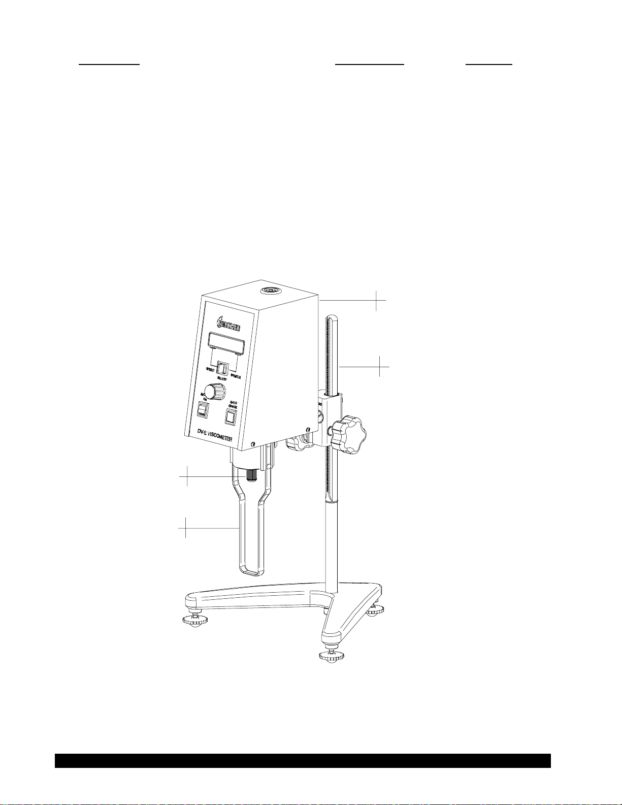
DV-E
Viscometer
Shipping
Cap
Guard Leg
Model A
Laboratory Stand
Figure I-1
Brookeld Engineering Labs., Inc. Page 6 Manual No. M98-350-J0912
Page 7
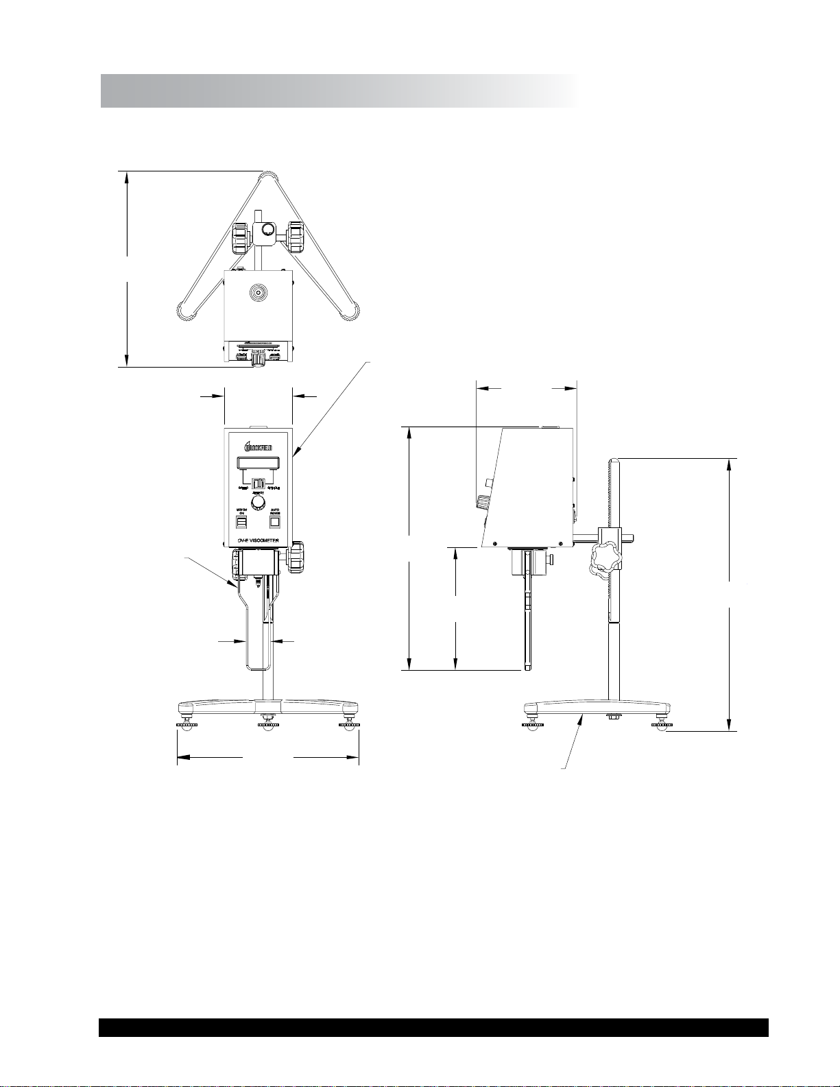
I.2 Instrument Dimensions
11 47/64”
[29.8 cm]
4 5/64”
[10.4 cm]
DV-E VISCOMETER
6”
[15.3 cm]
B-20Y
LV GUARD LEG
ASSEMBLY
1 7/16”
[3.7 cm]
10 7/8”
[27.6 cm]
14 41/64”
[37.2 cm]
LAB STAND BASE ASSEMBLY
Figure I-2
7 13/32”
[18.8 cm]
16 23/64”
[41.5 cm]
VS-1Y
Brookeld Engineering Labs., Inc. Page 7 Manual No. M98-350-J0912
Page 8

I.3 Utilities
Input Voltage: 115 VAC or 230 VAC
Input Frequency: 50/60 Hz
Power Consumption: Less than 20 WATTS
Power Cord Color Code:
United States
Outside United States
Hot (live) Black Brown
Neutral White Blue
Ground (earth) Green Green/Yellow
Input voltage can only be internally selected by a qualied technician from
Brookeld or an authorized Brookeld dealer.
I.4 Specications
Speeds: 0.3, 0.5, 0.6, 1.0, 1.5, 2.0, 2.5, 3.0, 4.0, 5.0, 6.0, 10, 12, 20, 30, 50, 60, 100 RPM
Weight: Gross Weight 20 lb 9 kg
Net Weight 17 lb 7.7 kg
Carton Volume 1.65 cu ft 0.05 m
3
Carton Dimension 19 x 10 x 15 in 48 x 25 x 38 cm
Operating Environment: 0°C to 40°C Temperature Range (32°F to 104°F)
20% - 80% R.H.: non-condensing atmosphere
Accuracy: ±1.0% Full Scale Range in Use (See Appendix D for details)
Reproducibility: 0.2% of Full Scale Range
Electrical Certications:
Conforms to CE Standards:
BSEN 61326:
Electrical equipment for measurement, control and laboratory use - EMC
requirements
BSEN 61010-1: Safety requirements for electrical equipment, for measurement, control
and laboratory use.
NOTICE TO CUSTOMERS:
This symbol indicates that this product is to be recycled at an appropriate collection center.
Users within the European Union:
Please contact your dealer or the local authorities in charge of waste management on how to
dispose of this product properly. All Brookeld ofces and our network of representatives
and dealers can be found on our website: www.brookeldengineering.com.
Users outside of the European Union:
Please dispose of this product according to your local laws.
Brookeld Engineering Labs., Inc. Page 8 Manual No. M98-350-J0912
Page 9
I.5 Set-Up
Note: “IQOQPQ”, a guideline document for installation, operation and
performance validation for your DV-E Viscometer, can be downloaded
from our website: www.brookeldengineering.com.
1. To assemble the Model A Laboratory Stand, place the upright rod into the base (refer to
assembly instructions in Appendix E).
2. Insert the mounting rod on the back of the DV-E Viscometer into the hole on the clamp
assembly. (Refer to Appendix E).
3. The Viscometer must be leveled. The level is adjusted using the three leveling screws on
the base. Adjust so that the bubble level on top of the DV-E is centered within the circle.
Note: Check level peroiodically during use.
4. Remove the Viscometer shipping cap from the pivot cup. This cap is designed to protect the
Viscometer spindle coupling nut during shipment. Do not attempt to operate the Viscometer
with the shipping cap in place! Save this cap for future use.
5. Make sure that the power switch at the rear of the DV-E is in the OFF (0) position. Connect
the power cord to the socket on the back panel of the instrument and plug it into the appropriate
AC power line.
The AC input voltage and frequency must be within the appropriate range as shown on
the name plate of the viscometer.
The DV-E must be earth grounded via its power mains cable plug/socket for electrical
safety and to ensure against electronic failure!!
I.6 Safety Symbols and Precautions
Safety Symbols
The following explains safety symbols which may be found in this operating manual.
Indicates hazardous voltages may be present.
Refer to the manual for specic warning or caution information to avoid personal injury
or damage to the instrument.
Precautions
If this instrument is used in a manner not specied by the manufacturer, the protection
provided by the instrument may be impaired.
This instrument is not intended for use in a potentially hazardous environment.
Brookeld Engineering Labs., Inc. Page 9 Manual No. M98-350-J0912
Page 10
In case of emergency, turn off the instrument and then disconnect the electrical cord from
the wall outlet.
The safety of any system, incorporating this instrument, is the responsibility of the
assembler of the system.
The user should ensure that the substances placed under test do not release poisonous,
toxic or ammable gases at the temperatures to which they are subjected to during the
testing.
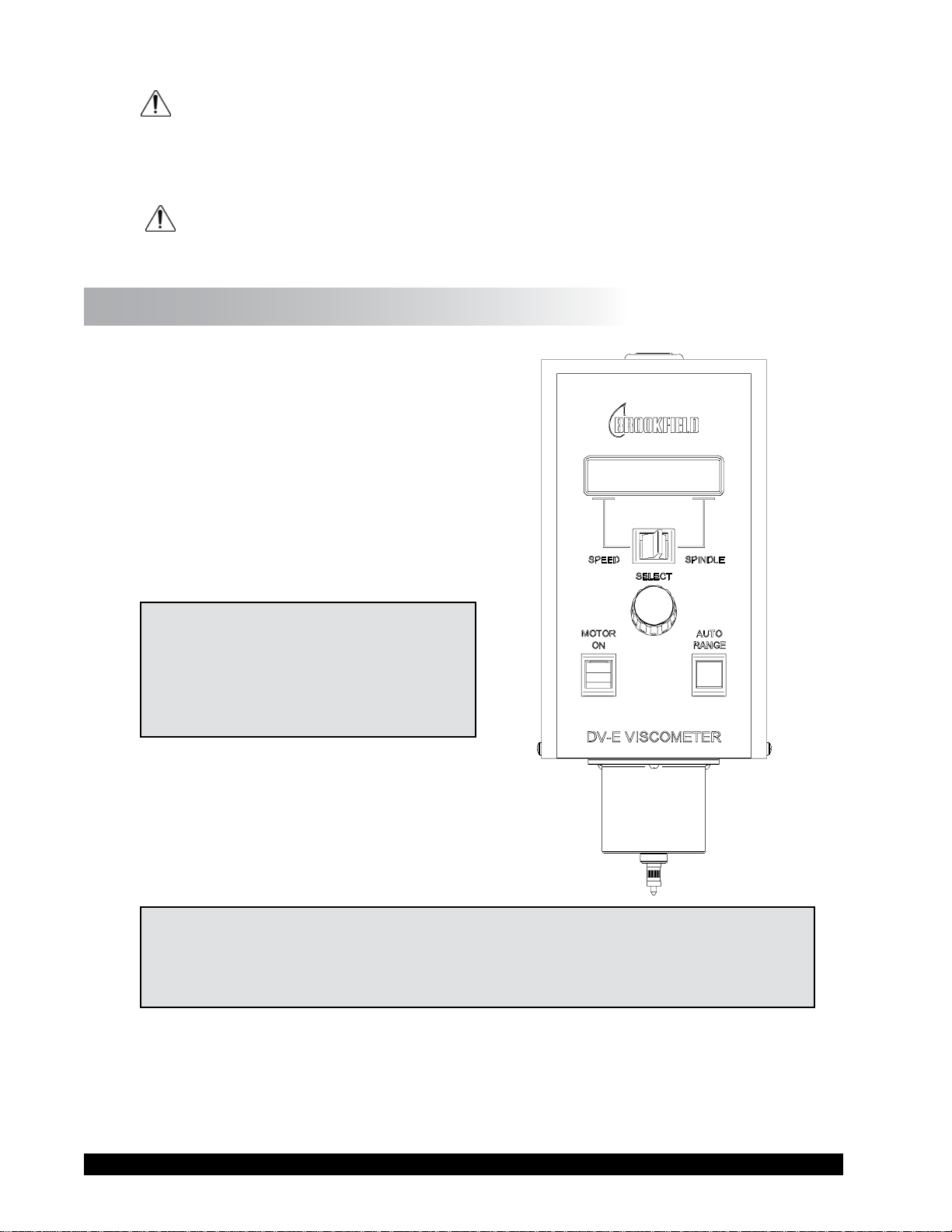
I.7 Instrument Controls
The following describes each switch’s function:
MOTOR ON
Turns the motor ON or OFF.
AUTO RANGE
Presents the maximum (100% torque) viscosity
attainable using the selected spindle at the
selected speed. This value is referred to as full
scale range. The allowable error for the viscosity
measurement is ± 1% of full scale range.
Note: Pressing and holding the AUTO
RANGE key during power on
will enable the viscosity display
to be read in either CGS (cP) or
SI (mPa•s) units.
SPEED/SPINDLE SWITCH
Sets the viscometer in either speed select or spindle
select (see Table C-1 in Appendix C) mode. When
set in the left position, the operator may select
speed of rotation. When set in the right position,
the operator may select spindle.
Note: This is a three (3) position switch. We recommend that the switch be set to the
middle position when nished with spindle or speed adjustment. This will prevent
Figure I-2
an accidental change of parameters during a test.
SELECT KNOB
This knob is used to scroll through the available speed or spindle selections (see Table C-1 in
Appendix C). This knob is active when the switch is set to the left (speed) or right (spindle) position.
Rotate the knob clockwise to increase value and counter-clockwise to decrease value.
Brookeld Engineering Labs., Inc. Page 10 Manual No. M98-350-J0912
Page 11

I.8 Cleaning
Instrument and Keypad: Clean with dry, non-abrasive cloth. Do not use solvents
Immersed Components (spindles): Spindles are made of stainless steel. Clean with non-
Make sure the instrument is in a decent working environment (dust-fr ee, moderate
temperature, low humidity, etc.).
Make sure the instrument is on a level surface.
Hands/ngers must be clean and free of residual sample. Not doing so may result
in deposit build up on the upper part of the shaft and caue interference between
the shaft and the pivot cup.
Be sure to remove the spindle from the instrument prior to cleaning. Note lefthand thread. Severe instrument damage may result if cleaned in place.
or cleaners.
abrasive cloth and solvent appropriate for sample material
that is not aggressive to immersed components.
When cleaning, do not apply excessive force which may result in bending spindles.
Brookeld Engineering Labs., Inc. Page 11 Manual No. M98-350-J0912
Page 12
II. GETTING STARTED
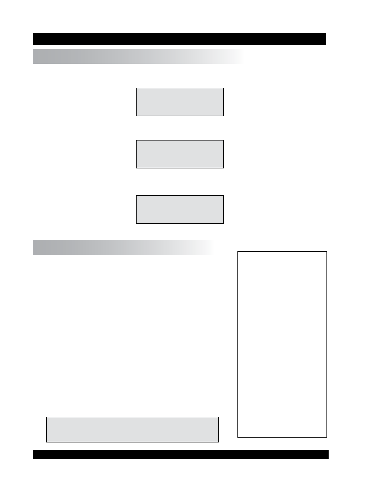
II.1 Power Up
Turn the power switch (located on the rear panel) to the ON (I) position. This will result in the
following screen display:
BROOKFIELD DV-E
RV VISCOMETER
Figure II-1
After a few seconds, the following screen appears:
BROOKFIELD DV-E
VERSION: 1.00
Figure II-2
After a short time, the display will clear and the default screen is displayed:
cP
10OFF % S02
Figure II-3
II.2 Spindle Selection
LVDV-E Viscometers are provided with a set of four spindles
and a narrow guardleg; RVDV-E Viscometers come with a set
of six spindles and a “wider” guardleg; HADV-E and HBDV-E
Viscometers come with a set of six spindles and no guardleg.
(See Appendix F for more information on the guardleg.)
The spindles are attached to the viscometer by screwing them to
the male coupling nut (see Figure II-4). Note that the spindles
and coupling have a left-hand thr ead. The lower shaft should
be held in one hand (lifted slightly), and the spindle screwed to
the left. The face of the spindle nut and the matching surface
on the coupling nut shaft should be smooth and clean to prevent
eccentric rotation of the spindle. Spindles can be identied by
the number on the side of the spindle coupling nut.
The DV-E must have a Spindle Entry Code number to calculate
viscosity values. The DV-E memory contains parameters for
all standard Brookeld spindles and the two digit entry code
for each spindle (the complete list of spindle entry codes may
be found in Appendix C).
Note: The DV-E will display the Spindle Entry Code
which was in use when the power was turned off.
Figure II-4
Brookeld Engineering Labs., Inc. Page 12 Manual No. M98-350-J0912
Page 13

Setting the SPEED/SPINDLE switch to the right position will allow the operator to adjust the
spindle selection. The SELECT knob can be rotated until the desired spindle number is selected.
Once the desired spindle number is shown on the display, set the SPINDLE/SPEED switch to the
middle position.
Note: Verify the proper spindle entry code for the selected spindle found in Appendix
C. Not all spindles have an entry code number that is the same as the spindle
number. For example: the spindle entry code for spindle LV-1 is 61 and the
spindle entry code for UL Adapter is 00.
The DV-E will begin to calculate using the new spindle parameters after the spindle number is
shown in the display.
Please see Brookeld publication, “More Solutions to Sticky Problems” (Chapter 3), for information
on how to select a spindle.
II.3 Speed Selection & Setting
There are 18 rotational speeds available on the DV-E Viscometer. These speeds correspond to the
standard LVF, LVT, RVF, RVT, HAT and HBT Dial Viscometers models and they are combined
sequentially. See Table 1 below.
Table 1: DV-E Speeds
0.3 10
0.5 12
0.6 20
1.0 30
1.5 50
2.0 60
2.5 100
3.0
4.0
5.0
6.0
Table
Setting the SPEED/SPINDLE switch in the left position will allow the operator to adjust the speed
selection. The SELECT knob can be rotated until the desired speed is selected. Once the desired
speed is shown on the display, set the SPINDLE/SPEED switch to the middle position.
The viscometer will rotate the spindle at the selected speed when the motor switch is in the ON
position. A motor on condition is indicated on the display by RPM shown beside the speed. When
the motor switch is in the OFF position, OFF will be displayed beside the speed.
Brookeld Engineering Labs., Inc. Page 13 Manual No. M98-350-J0912
Page 14

cP
12RPM % S02
(MOTOR ON)
Figure II-5
cP
12OFF % S02
(MOTOR OFF)
Figure II-6
Note: When the motor switch is in the ON position, any change to the selected speed
will be effective immediately. When collecting data at multiple speeds, you
may wish to leave the SPEED/SPINDLE switch in the left position to facilitate
speed changes. Also, when the motor switch is turned off, the display will hold
the last measured torque value and measured viscosity.
The DV-E Viscometer employs an optical signal pick-up inside the instrument to detect the torque
value of the calibrated spring. This optical signal pick-up is recorded four times per revolution of
the spindle. When the spindle begins to rotate at a dened speed, four torque values are recorded
during the rst full revolution of the spindle and averaged together. The display reports the average
value for both torque (%) and viscosity (cP or mPa•s). Thereafter, the next torque value recorded by
the optical signal pick-up is averaged together with the three preceding torque values and the newly
calculated torque (%) and viscosity (cP or mPa•s) values are then displayed. This 4x revolution
pick-up and display continues as long as the motor is on.
This algorithm in the instrument rmware is used for all viscosity and torque readings. Consequently,
the wait time to observe the initial displayed readings for torque and viscosity increase as you go
to lower speeds.
It may also be necessary to allow time for the indicated reading to stabilize.
Note: At speeds of 1 RPM and lower, additional time may be required to allow for
complete deection of the torque sensor. The % (torque) and cP (viscosity) will
ash until 1 revolution is achieved and the % torque value is greater than 10%.
The time required for stabilization will depend on the speed at which the Viscometer is running
and the characteristics of the sample uid. For maximum accuracy, readings below 10% should be
avoided. Additional information on making viscosity measurements is available in Appendix B or
the Brookeld publication “
More Solutions to Sticky Problems” .
The DV-E Viscometer will remember the selected speed and spindle when power is turned off. On
start-up, the Viscometer will be set to the previously selected spindle and speed.
Please see Brookeld publication “More Solutions to Sticky Problems” (Chapter 3) for information
on how to select a speed.
Brookeld Engineering Labs., Inc. Page 14 Manual No. M98-350-J0912
Page 15

II.4 Autorange and CGS or SI Units Selection
The
AUTO RANGE key allows you to determine the maximum calculated viscosity (full scale
reading) possible with the curr ent spindle/speed setting. Pressing the key at any time will cause
the current viscosity display to change and show that maximum viscosity. The screen torque display
will now display “%100” to indicate this special condition. This maximum viscosity and %100
value will be displayed for as long as the
AUTO RANGE key is depressed. Figure II-7 shows the
AUTO RANGE function for the situation where the No. 2 RV spindle is rotating at 10 RPM. The
.
full scale range is 4000 cP (or 4000 mPa
s).
cP 4000
10RPM %100 S02
Figure II-7
Pressing and holding the AUTO RANGE key during power on will enable the viscosity unit
displayed to toggle between CGS (cP) and SI (mPa•s) units. To change the unit format:
1. Turn the power off.
2. Press and hold the AUTO RANGE key and turn the power ON.
The DV-E will retain the unit selection when the viscometer is turned OFF.
CGS SI
.
Viscosity: cP mPa
s
1 cP = 1 mPa•s
II.5 Out of Range
The DV-E gives indications for out of specication or out-of-range operation. When % (Torque)
readings exceed 100.0 % (over-range), the display changes to that shown in Figur e II-8. You must
either reduce the speed or use a smaller size spindle to correct this condition.
cP EEEE
10RPM %EEEE S02
Figure II-8
If you operate at spindle speeds that produce % (Torque) below 10.0 % (under-range), the DV-E
displays both % (Torque) and cP (Viscosity) with ashing unit designations, as shown is Figure
II-9. You must either increase speed or use a larger size spindle to correct this condition.
The parameters of % (Torque) and cP (Viscosity) will also ash prior to one complete spindle
revolution. It is not recommended that readings are taken while parameters are ashing.
Brookeld Engineering Labs., Inc. Page 15 Manual No. M98-350-J0912
Page 16

cP 360
10RPM % 9.0 S02
Figure II-9
Negative % (Torque) will be displayed as shown in Figure II-10. Viscosity values will be displayed
as “- - - -” when the % (Torque) is below zero.
cP ---10RPM %-1.0 S02
Figure II-10
II.6 Operation
The following procedure is outlined for making a viscosity measurement in the recommended 600
mL low form Grifn beaker.
1. Insert and center spindle in the test material until the uid’s level is at the immersion
groove on the spindle’s shaft. With a disc-type spindle, it is sometimes necessary to tilt the
spindle slightly while immersing to avoid trapping air bubbles on its under side surface.
(Brookeld recommends that you immerse the spindle in this fashion before attaching it to
the Viscometer.)
2. Mount the guardleg on the DV-E Viscometer (LV and RV series). Be sure that the motor
is OFF before attaching the spindle. Select a spindle and attach it to the spindle coupling
nut. Lift the shaft slightly, holding it rmly with one hand while screwing the spindle on
with the other (note left-hand thread). Avoid putting side thrust on the shaft.
3. To make a viscosity measurement, select a speed and follow the instructions in Sections II.2
and II.3. Allow time for the indicated reading to stabilize. The time required for stabilization
will depend on the speed at which the Viscometer is running and the characteristics of the
sample uid. For maximum accuracy, ashing readings below 10% should be avoided.
Additional information on making viscosity measurements is available in Appendix B or
the Brookeld publication
4. Switch the
MOTOR ON/OFF switch to turn the motor “OFF” when changing a spindle or
“More Solutions to Sticky Problems”.
changing samples. Remove spindle before cleaning.
5. Interpretation of results and the instrument’s use with non-Newtonian and thixotropic
materials is discussed in the booklet, “More Solutions to Sticky Problems”, and in Appendix
B - Variables in Viscosity Measurement.
Brookeld Engineering Labs., Inc. Page 16 Manual No. M98-350-J0912
Page 17

Appendix A - Viscosity Ranges
Appendix A - Viscosity Ranges
LV and RV,HA,HB Viscometers
Viscosity Range (cP)
Viscometer Minimum Maximum
LVDV-E 15 2 M
RVDV-E 100* 13 M
HADV-E 200* 26 M
HBDV-E 800* 106 M
*Minimum viscosity with optional RV/HA/HB-1 spindle
Small Sample Adapter (SSA) and Thermosel (Tsel)
SSA/
Thermosel
Spindle
SC4-16 (SSA) 0.29 N 120 - 400 K
SC4-18 (SSA/Tsel) 1.32 N 3 - 10 K
SC4-25 (SSA) 0.22 N 800 - 1.60 K
SC4-31 (SSA/Tsel) 0.34 N 30 - 100 K
SC4-34 (SSA/Tsel) 0.28 N 60 - 200 K
HT-81 (Tsel) 1.29 N 3.5 - 10 K
SC4-82 (SSA) 1.29 N 3.5 - 10 K
SC4-83 (SSA) 1.29 N 11.0 - 38 K
SSA/
Thermosel Spindle
SC4-14 (SSA) 0.40N 1.25K - 4.2 M
SC4-15 (SSA) 0.48N 500 - 1.7 M
SC4-21 (SSA/Tsel) 0.93N 50 - 170 K 100 - 300 K 400 - 1.3 M
SC4-27 (SSA/Tsel) 0.34N 250 - 830 K 500 - 1.7 M
SC4-28 (SSA/Tsel) 0.28N 500 - 1.7 M
SC4-29 (SSA/Tsel) 0.25N 1 K - 3.3 M
HT-81 (Tsel) 1.29N 36 - 10 K 73 - 10 K 292 - 10 K
SC4-82 (SSA) 1.29N 36 - 10 K 73 - 10 K 292 - 10 K
SC4-83 (SSA) 1.29N 121 - 50 K
Shear
Rate
(1/SEC)
Shear Rate
(1/SEC)
RVDV-E HADV-E HBDV-E
2.5 K - 8.3 M 10 K - 33.3 M
1 K - 3.3 M 4 K - 13.3 M
1 K - 3.3 M 4 K - 13.3 M
2 K - 6.7 M 8 K - 26.7 M
242 - 50 K 970 - 50 K
Viscosity (cP)
LVDV-E
Viscosity (cP)
2 K - 6.7 M
cP = Centipoise K = 1,000 M = 1,000,000 N = RPM
Brookeld Engineering Labs., Inc. Page 17 Manual No. M98-350-J0912
Page 18

UL Adapter
Viscosity (cP)
Shear Rate
UL Spindle
YULA-15 or 15Z 1.224N 1.0 - 2 K 6.4 - 2 K 12.8 - 2 K 51.2 - 2 K
(1/SEC)
LVDV-E RVDV-E HADV-E HBDV-E
DIN Adapter Accessory
Viscosity (cP)
DAA Spindle
Shear Rate
(1/SEC)
LVDV-E RVDV-E HADV-E HBDV-E
85 1.29N
86 1.29N
87 1.29N
1.2 - 3.8 K 12 - 5 K 24 - 5 K 98 - 5 K
3 - 10 K 36 - 10 K 73 - 10 K 292 - 10 K
11 - 38 K 12 - 50 K 242 - 50 K 970 - 50 K
Spiral Adapter
Viscosity (cP)
Shear Rate
DAA Spindle
SA-70 0.68 - 68 100 - 98 K 1 M - 1 M 2 M - 2 M 8 M - 8.4 M
(1/SEC)
(1-100 RPM)
LVDV-E RVDV-E HADV-E HBDV-E
Helipath with T-Bar Spindles
T-Bar
Spindle
T-A 156 - 62 K 2 M - 400 K 4 M - 800 K 16 M - 3.2 M
T-B 312 - 124 K 4 M - 800 K 8 M - 1.6 M 32 M - 6.4 M
T-C 780 - 312 K 10 M - 2 M 20 M - 4 M 80 M - 16 M
T-D 1.5 M - 624 K 20 M - 4 M 40 M - 8 M 160 M - 32 M
T-E 3.9 M - 1.5 M 50 M - 10 M 100 M - 20 M 400 M - 80 M
T-F 7.8 M - 3.1 M 100 M - 20 M 200 M - 40 M 800 M - 160 M
LVDV-E RVDV-E HADV-E HBDV-E
Viscosity (cP)
cP = Centipoise K = 1,000 M = 1,000,000 N = RPM
Brookeld Engineering Labs., Inc. Page 18 Manual No. M98-350-J0912
Page 19

In taking viscosity measurements with the DV-E Viscometer, there are two considerations which
pertain to the low viscosity limit of effective measurement.
1) Viscosity measurements should be accepted within the equivalent % Torque Range from
10% to 100% for any combination of spindle/speed rotation.
2) Viscosity measurements should be taken under laminar ow conditions, not under turbulent
ow conditions.
The rst consideration has to do with the accuracy of the instrument. All DV-E Viscometers have a
full scale range accuracy of (+/-) 1% of any spindle/speed rotation. We discourage taking readings
below 10% of range because the potential viscosity error of (+/-) 1% is a relatively high number
compared to the instrument reading.
The second consideration involves the mechanics of uid ow. All rheological measurements of
uid ow properties should be made under laminar ow conditions. Laminar ow is ow wherein
all particle movement is in layers directed by the shearing force. For rotational systems, this means
all uid movement must be circumferential. When the inertial forces on the uid become too great,
the uid can break into turbulent ow wherein the movement of uid particles becomes random
and the ow can not be analyzed with standard math models. This turbulence creates a falsely high
viscometer reading with the degree of non-linear increase in reading being directly related to the
degree of turbulence in the uid.
For the following geometries, we have found that an approximate transition point to turbulent ow
occurs:
1) No. 1 LV Spindle: 15 cP at 60 RPM
2) No. 1 RV (optional) Spindle: 100 cP at 50 RPM
3) UL Adapter: 0.85 cP at 60 RPM
Turbulent conditions will exist in these situations whenever the RPM/cP ratio exceeds the values listed
above. The viscosity at which turbulence starts is still at best a guess. Because it is a relationship
between viscous and inertial forces, it can vary dramatically from uid to uid. Turbulence starts
as a small deviation or increase in viscosity for a Newtonian uid. Basically there is no specic
shear that it starts at, only an approximate region of shear depending on the uid.
Brookeld Engineering Labs., Inc. Page 19 Manual No. M98-350-J0912
Page 20

Appendix B - Variables in Viscosity Measurement
As with any instrument measurement, there are variables that can affect a viscometer measurement.
These variables may be related to the instrument (viscometer), or the test uid. Variables related
to the test uid deal with the rheological properties of the uid, while instrument variables would
include the viscometer design and the spindle geometry system utilized.
Rheological Properties
Fluids have different rheological characteristics that can be described by viscometer measurements.
We can then work with these uids to suit the lab or process conditions.
There are two categories of uids:
Newtonian - These uids have the same viscosity at different Shear Rates (different
RPM’s) and are called Newtonian over the Shear Rate range they are
measured.
Non-Newtonian - These uids have different viscosities at different shear rates (different
RPM’s). They fall into two groups:
1) Time Independent
2) Time Dependent
Time Independent means that the viscosity behavior does not change as a function of time when
measuring at a specic shear rate.
Pseudoplastic - A pseudoplastic material displays a decrease in viscosity with an increase
in shear rate, and is also known as “shear thinning”. If you take viscometer
readings from a low to a high RPM and then back to the low RPM, and
the readings fall upon themselves, the material is time independent
pseudoplastic and shear thinning.
Time Dependent means that the viscosity behavior changes as a function of time when measuring
at a specic shear rate.
Thixotropic - A thixotropic material has decreasing viscosity under constant shear rate.
If you set a viscometer at a constant speed recording viscosity values over
time and nd that the viscosity values decrease with time, the material is
thixotropic.
Brookeld publication, “More Solutions to Sticky Problems”, includes a more detailed discussion
of rheological properties and non-Newtonian behavior.
Viscometer Related Variables
Most uid viscosities are found to be non-Newtonian. They are dependent on Shear Rate and the
spindle geometry conditions. The specications of the viscometer spindle and chamber geometry
will affect the viscosity readings. If one reading is taken at 2.5 rpm, and a second at 50 rpm, the
two viscosity values produced will be different because the readings were made at different shear
rates. The faster the spindle speed, the higher the shear rate.
Brookeld Engineering Labs., Inc. Page 20 Manual No. M98-350-J0912
Page 21

The shear rate of a given measurement is determined by: the rotational speed of the spindle, the
size and shape of the spindle, the size and shape of the container used and therefore, the distance
between the container wall and the spindle surface.
A repeatable viscosity test should control or specify the following:
1) Test temperature
2) Sample container size (or spindle/chamber geometry)
3) Sample volume
4) Viscometer model
5) Spindle used (if using LVDV-E (#1-4) or RVDV-E (#2-7) attach the guard leg)
6) Test speed or speeds (or the shear rate)
7) Length of time or number of spindle revolutions to record viscosity.
Brookeld Engineering Labs., Inc. Page 21 Manual No. M98-350-J0912
Page 22

Appendix C - Spindle and Model Codes
Appuuoijpoiendix C - Spindle and Model Codes
Each spindle has a two digit code which is scrolled via the select knob on the DV-E. The spindle
code directs the DV-E to calculate viscosity for the spindle that is being used. The spindle multiplier
constant (SMC) is used to calculate full scale viscosity range for any spindle/speed combination.
Use of Guard Leg is required. Spindle codes are listed in Table C-1.
SPINDLE CODE SMC
01 RV1 (optional) 01 1
02 RV2 02 4
03 RV3 03 10
04 RV4 04 20
05 RV5 05 40
06 RV6 06 100
07 RV7 07 400
H01 HA1
H02 HA2 02 4
03 HA3 03 10
04 HA4 04 20
05 HA5 05 40
06 HA6 06 100
07 HA7 07 400
H01 HB1
H02 HB2 02 4
03 HB3 03 10
04 HB4 04 20
05 HB5 05 40
06 HB6 06 100
07 HB7 07 400
61 LV1 61 6.4
62 LV2 62 32
63 LV3 63 128
64 LV4 or 4B2 64 640
65 LV5
66 LV2C 66 32
67 LV3C 67 128
SA -70 Spiral 70 105
V-71 71 2.62
(optional) 01 1
(optonal) 01 1
(optional) 65 1280
SPINDLE CODE SMC
V-72 72 11.1
V-73 73 53.5
V-74 74 543
V-75 75 213
T-A 91 20
T-B 92 40
T-C 93 100
T-D 94 200
T-E 95 500
T-F 96 1000
ULA 00 0.64
DIN-ULA 85 1.22
TSEL-DIN-81 81 3.7
SSA-DIN-82 82 3.75
SSA-DIN-83 83 12.09
ULA-DIN-85 85 1.22
ULA-DIN-86 86 3.65
ULA-DIN-87 87 12.13
SC4-14 14 125
SC4-15 15 50
SC4-16 16 128
SC4-18 18 3.2
SC4-21 21 5
SC4-25 25 512
SC4-27 27 25
SC4-28 28 50
SC4-29 29 100
SC4-31 31 32
SC4-34 34 64
Table C-1
Brookeld Engineering Labs., Inc. Page 22 Manual No. M98-350-J0912
Page 23

VISCOMETER TORQUE CONSTANT MODEL CODE
MODEL TK ON DV-E SCREEN
LVDV-E 0.09373 LV
RVDV-E 1 RV
HADV-E 2 HA
HBDV-E 8 HB
SPECIAL ORDER TORQUE SPRINGS
VISCOMETER TORQUE CONSTANT MODEL CODE
MODEL TK ON DV-E SCREEN
2.5xLVDV-E 0.2343 2.5LV
5xLVDV-E 0.4686 5LV
1/4 RVDV-E 0.25 1/4RV
1/2 RVDV-E 0.5 1/2RV
2xHADV-E 4 2HA
2.5xHADV-E 5 2.5HA
2xHBDV-E 16 2HB
2.5xHBDV-E 20 2.5HB
Table C-2
This equation can be used to calculate the maximum viscosity that can be measured when using a
specic speed/spindle combination.
Full Scale Viscosity Range (FSR) = TK * SMC *
10,000
RPM
The units for FSR are in centipoise (cP). An example is shown in Appendix D.
Brookeld Engineering Labs., Inc. Page 23 Manual No. M98-350-J0912
Page 24

Appendix D - Calibration Check Procedures
Brookeld’s accuracy statement for viscometers used with standard spindles is +/- 1% of full scale
range. When measuring viscosity with a specic spindle rotating at a dened speed, the maximum
viscosity that can be measured is dened as full scale range. For digital viscometers, this value is
easily determined by pressing the “AUTORANGE” key. The display will how the full scale range
viscosity in cP or mPa•s and the torque value will show “100%”. Multiply the full scale range
viscosity by 1% to determine the accuracy of any future measurement made with that spindle/speed
combination.
When using the following accessory devices with your viscometer, the accuracy is +/- 2%. Dimensional
tolerances in the accessory device allow for the increase from +/- 1% to +/-2%.
• Small Sample Adapter
• Thermosel
• Ul Adapter
• DIN Adapter
• Spiral Adapter
For more help you can go to the website,
www.brookeldengineering.com, and download the video.
The accuracy of the DV-E is veried using Viscosity Standard Fluids which are available from
Brookeld Engineering Laboratories or your local Brookeld agent. Viscosity standards are
Newtonian, and therefore, have the same viscosity regardless of spindle speed (or shear rate).
Viscosity standards, calibrated at 25°C, are shown in Table D-1.
Container size: For Viscosity Standards < 30,000 cP, use a 600 mL Low Form Grifn Beaker
having a working volume of 500 mL.
For Viscosity Standards ≥ 30,000 cP, use the uid container.
Inside Diameter: 3.25”(8.25cm)
Height: 4.75”(12.1cm)
Note: Container may be larger, but may not be smaller.
Temperature: As stated on the uid standard label: (
Conditions: The DV-E should be set up according to the operating instructions. The water
bath should be stabilized at test temperature. Viscometers with the letters “LV”
or “RV” in the model designation should have the guard leg attached when using
Viscosity Standard Fluids below 30,000 cP.
+/-) 0.1°C
Brookeld Engineering Labs., Inc. Page 24 Manual No. M98-350-J0912
Page 25

Normal 25°C Standard Fluids
Viscosity (cP) Viscosity (cP)
High Temperature Standard Fluids for use
with Thermosel Accessory
HT-30,000
HT-60,000
HT-100,000
25°C, 93.3°C, 149°C
10
50
100
500
5
5,000
12,500
30,000
60,000
Calibrated at three viscosity/temperatures
100,000
1000
Refer to the Brookeld Catalog for more information.
Table D-1(Silicone Oils)
Brookeld Viscosity Standard Fluid - General Information
We recommend that Brookeld Viscosity Standard Fluids be replaced on an annual basis, one year
from date of initial use. These uids are pure silicone and are not subject to change over time.
However, exposure to outside contaminants through normal use requires replacement on an annual
basis. Contamination may occur by the introduction of solvent, standard of different viscosity or
other foreign material.
Viscosity Standard Fluids may be stored under normal laboratory conditions. Disposal should be
in accordance with state, local and federal regulations as specied on the material safety data sheet.
Brookeld Engineering Laboratories does not recertify Viscosity Standard Fluids. We will issue
duplicate copies of the Certicate of Calibration for any uid within two years of the purchase date.
Brookeld Viscosity Standard Fluids are reusable provided they are not contaminated. Normal
practice for usage in a 600 ml beaker is to return the material from the beaker back into the bottle.
When using smaller volumes in accessories such as Small Sample Adapter, UL Adapter, Thermosel
or Spiral Adapter, the uid is normally discarded.
Calibration Procedure for LV #1-3 (#61-63) and RV, HA, HB (#2-6) Brookeld spindles:
Note: The LV #4 (#64) and RV, HA, HB #7 have been omitted from this proce-
dure. Brookeld does not recommend the use of these spindles to perform a
calibration check on your instrument. Reasons pertain to the small amount
of sample surface area that makes contact with the viscosity standard, the
difculty of establishing the immersion mark precisely and the need for
precise temperature control at 25°C in the immediate vicinity of the spindle.
Follow these steps using one of the recommended spindles to verfy calibration on you instrument:
1) Place the viscosity standard uid (in the proper container) into the water bath.
2) Lower the DV-E into measurement position (with guard leg if LV or RV series viscometer
is used).
3) Attach the spindle to the viscometer. If you are using a disk shaped spindle, avoid trapping
Brookeld Engineering Labs., Inc. Page 25 Manual No. M98-350-J0912
Page 26

air bubbles beneath the disk by rst immersing the spindle at an angle, and then connecting
it to the viscometer.
4) The viscosity standard uid, together with the spindle and guard leg (if supplied), should
be immersed in the bath for a minimum of 1 hour, stirring the uid periodically, prior to
taking measurements.
5) After 1 hour, check the temperature of the viscosity standard uid with an accurate thermometer.
Fluid must be within ± 0.1°C of the specied temperature, normally 25°C. Allow longer
soak time if required to come to test temperature.
6) If the uid is at test temperature, measure the viscosity and record the viscometer reading.
Note: The spindle must rotate at least ve (5) times before readings are taken.
7) The viscosity reading should equal to the cP value on the viscosity uid standard to within
the combined accuracies of the viscometer and the standard (as discussed in Interpretation
of Calibration Test Results at the end of this Appendix).
Calibration Procedure for a Small Sample Adapter
When a Small Sample Adapter is used, the water jacket is connected to the water bath and the water
is stabilized at the proper temperature:
1) Put the proper amount of viscosity standard uid into the sample chamber. The amount varies
with each spindle/chamber combination. (Refer to the Small Sample Adapter instruction
manual.)
2) Place the sample chamber into the water jacket.
3) Put the spindle into the test uid and attach the extension link, coupling nut and free hanging
spindle (or directly attach the solid shaft spindle) to the DV-E.
4) Allow 30 minutes for the viscosity standard, sample chamber and spindle to reach test
temperature.
5) Measure the viscosity and record the viscometer reading.
Note: The spindle must rotate at least ve (5) times before a viscosity reading is taken.
Calibration Procedure for a Thermosel System
A two-step process is recommended for the Thermosel.
A) Evaluate the calibration of the Viscometer alone according to the procedure outlined in
this section, entitled Calibration Procedure for LV #1-3 (#61-63) and RV, HA, HB #2-6
Brookeld spindles.
B) Evaluate the Viscometer with the Thermosel according to the procedure described below.
Brookeld Engineering Labs., Inc. Page 26 Manual No. M98-350-J0912
Page 27

When a Thermosel is used, the controller stabilizes the Thermo Container at the test
temperature.
1) Install the tube end cap and put the proper amount of HT viscosity standard uid into the
HT-2 or HT-2DB sample chamber. The amount varies with the spindle used. (Refer to
the Thermosel instruction manual).
2) Place the sample chamber into the Thermo Container.
3) Put the spindle into the test uid and attach the extension link, coupling nut and free
hanging spindle (or directly attach the solid shaft spindle) to the DV-E.
4) Allow 30 minutes for the viscosity standard, sample chamber and spindle to reach test
temperature.
5) Measure the viscosity and record the viscometer reading.
Note: The spindle must rotate at least ve (5) times before a viscosity reading is taken.
Calibration Procedure for UL Adapter
When a UL Adapter is used, the water bath should be stabilized at the proper temperature:
1) Install the tube end cap and put the proper amount of viscosity standard uid into the UL
Tube. (Refer to the UL Adapter instruction manual).
2) Attach the spindle (with extension link and coupling nut) onto the DV-E.
3) Attach the tube to the mounting channel.
4) Lower the tube into the water bath reservoir, or if using the ULA-40Y water jacket, connect
the inlet/outlets to the bath external circulating pump.
5) Allow 30 minutes for the viscosity standard, sample chamber and spindle to reach test
temperature.
6) Measure the viscosity and record the viscometer reading.
Note: The spindle must rotate at least ve (5) times before a viscosity reading is taken.
Calibration Procedure for DIN Adapter Accessory
When a DIN Adapter is used, the water bath should be stabilized at the proper temperature:
1) Put the proper amount of viscosity standard uid into the UL Tube. (Refer to the DAA
instruction manual).
2) Attach the spindle (with extension link and coupling nut) onto the DV-E.
Brookeld Engineering Labs., Inc. Page 27 Manual No. M98-350-J0912
Page 28

3) Attach the tube to the mounting channel.
4) Lower the tube into the water bath reservoir, or if using the ULA-40Y water jacket, connect
the inlet/outlets to the bath external circulating pump.
5) Allow 30 minutes for the viscosity standard, sample chamber and spindle to reach test
temperature.
6) Measure the viscosity and record the viscometer reading.
Note: The spindle must rotate at least ve (5) times before a viscosity reading is taken.
Calibration Procedure for Spiral Adapter
1) Place the viscosity standard uid (in the proper container) into the water bath.
2) Attach the spindle to the viscometer. Attach chamber (SA-1Y) and clamp to the viscometer.
3) Lower the DV-E into measurement position. Operate the viscometer at 50 or 60 RPM until
the chamber is fully ooded.
4) The viscosity standard uid, together with the spindle, should be immersed in the bath for
a minimum of 1 hour, stirring the uid periodically (operate at 50 or 60 RPM periodically),
prior to taking measurements.
5) After 1 hour, check the temperature of the viscosity standard uid with an accurate thermometer.
6) If the uid is at test temperature (
measure the viscosity and record the viscometer reading.
Note: The spindle must rotate at least ve (5) times or for one minute, whichever is
greater before the readings are taken.
7) The viscosity reading should equal the cP value on the viscosity uid standard to within the
combined accuracies of the viscometer and the standard (as discussed in the section entitled,
Interpretation of Calibration Test Results). However, instrument accuracy is ±2% of the
maximum viscosity range and not the standard 1%.
Interpretation of Calibration Test Results:
When verifying the calibration of the DV-E, the instrument and viscosity standard uid error
must be combined to calculate the total allowable error.
The DV-E is accurate to (
Brookeld Viscosity Standards Fluids are accurate to (+/-) 1% of their stated value.
+/-) 1% of any full scale spindle/speed viscosity range.
+/- 0.1°C of the specied temperature, normally 25°C),
EXAMPLE 1: Calculate the acceptable range of viscosity using RVDV-E with RV-3 Spindle
at 2 RPM; Brookeld Standard Fluid 12,500 with a viscosity of 12,257 cP at
25°C:
Brookeld Engineering Labs., Inc. Page 28 Manual No. M98-350-J0912
Page 29

1) Calculate full scale viscosity range using the equation:
Full Scale Viscosity Range
[cP] = TK
SMC
*
Where: TK = 1.0 from Table C-2 (in Appendix C)
SMC = 10 from Table C-1 (in Appendix C)
Full Scale Viscosity Range =
1 * 10 * 10,000
2
10,000
*
RPM
= 50,000 cP
The viscosity is accurate to (
2) The viscosity standard uid is 12,257 cP. Its accuracy is (
(
+/-)122.57 cP.
+/-) 500 cP (which is 1% of 50,000)
+/-)1% of 12,257 or
3) Total allowable error is (122.57
4) Therefore, any viscosity reading between 11,634.4 and 12,879.6 cP indicates that the
viscometer is operating correctly. Any reading outside these limits may indicate a viscometer
problem. Contact the Brookeld technical sales department or your local Brookeld dealer/
distributor with test results to determine the nature of the problem.
EXAMPLE 2: Calculate the acceptable range of viscosity using RVDV-E with Small Sample
Adapter at 10RPM; Brookeld Standard Fluid 12,500 with a viscosity of 12,257
cP at 25°C:
1) Determine full scale range by pressing the “AUTORANGE” key on your instrument, The
display shows 25,000cP. The viscosity is accurate to +/- 500 cP (which is 2% of 25,000
cP).
2) The viscosity standard uid is 12,257 cP. Its accuracy is (
(
3) Total allowable error is (122.57
4) Therefore, any viscosity reading between 11,634.4 and 12,879.6 cP indicates that the
+/-)122.57 cP.
viscometer is operating correctly. Any reading outside these limits may indicate a viscometer
problem. Contact the Brookeld technical sales department or your local Brookeld dealer/
distributor with test results to determine the nature of the problem.
+ 500) cP = (+/-) 622.57 cP.
+/-)1% of 12,257 or
+ 500) cP = (+/-) 622.57 cP.
Brookeld Engineering Labs., Inc. Page 29 Manual No. M98-350-J0912
Page 30

Appendix E - Model A Laboratory Stand
1
UP/DOWN
KNOB
VISCOMETER
HEAD CLAMP
KNOB
TENSION
SCREW
BROOKFIELD
LABORATORY
VISCOMETER
5
4
3
ITEM PART #
VS-CRA-14S
1
2
VS-1
VS-3
3
4
VS-21
BLM-4E
5
6
VSXA-17A
*for use with Thermosel and Water Baths
UPRIGHT ROD AND CLAMP ASSEMBLY
BASE
LEVELING SCREW
JAM NUT
ROD EXTENSION - 4” LONG *
CLAMP ASSEMBLY FOR EXPLOSION PROOF
DESCRIPTION
Figure E-1
2
QTY.
1
1
3
1
OPTIONAL
OPTIONAL
Brookeld Engineering Labs., Inc. Page 30 Manual No. M98-350-J0912
Page 31

Unpacking
Check carefully to see that all the components are received with no concealed damage.
1 base (VS-1) 1 jam nut (VS-21)
3 leveling screws (VS-3) 1 clamp and rod assembly (VS-CRA-14S)
Open and discard all packaging materials for the base. Remove the three (3) leveling screws from
the base. Remove the jam nut from the upright rod.
Assembly (Refer to Figure E-1)
Screw the leveling screws into the base. Insert the threaded end of the upright rod into the hole in
the top of the base and attach the jam nut to the rod on the underside of the base. With the clamp
and rod assembly facing forward (the word “front” should be facing the operator), towards the open
part of the “V” in the base, gently tighten the jam nut.
Viscometer Mounting
The VS-CRA-14S clamp and rod assembly should be positioned so that the word ‘front’ is facing
the operator. This will ensure the cut-away slot of the clamp assembly will align properly with the
machined key ridge of the viscometer handle. Insert the viscometer rod into the cut-away hole of
the clamp assembly. Adjust the instrument level until the bubble is centered within the target and
tighten the clamp knob.
The tension screw (see Item #1, Figure E-1) on the front side of the clamp assembly should be loosened or tightened as necessay to provide smooth height
adjustment and adequate support for the Viscometer.
Center the Viscometer relative to the stand base and retighten the jam nut as required. Refer ring
to the Viscometer bubble level, adjust the leveling screws until the instrument is level.
Operation
Rotate the Up/Down Knob (see Figure E-1) to raise or lower the viscometer.
Brookeld Engineering Labs., Inc. Page 31 Manual No. M98-350-J0912
Page 32

Appendix F - The Brookeld Guardleg
The guard leg was originally designed to protect the spindle during use. The rst applications
of the Brookeld Viscometer included hand held operation while measuring uids in a 55
gallon drum. It is clear that under those conditions the potential for damage to the spindle
was great.
The current guard leg is a band of metal in the shape of the letter U with a bracket at the
top that attaches to the pivot cup of a Brookeld Viscometer/Rheometer. A guard leg is
supplied with all LV and RV series instruments, but not with the HA or HB series. It’s shape
is designed to accommodate the spindles of the appropriate spindle set; therefore, the RV
guard leg is wider than the LV, as shown in Figure F-1, due to the large diameter of the RV
#1 (optional) spindle. They are not interchangeable.
The calibration of the Brookeld Viscometer/Rheometer is determined using a 600 ml Low
Form Grifn Beaker. The calibration of LV and RV series instruments includes the guard leg.
The beaker wall (for HA/HB instruments) or the guard leg (for LV/RV instruments) dene
what is called the “outer boundary” of the measurement. The spindle factors for the LV,
RV, and HA/HB spindles were developed with the above boundary conditions. The spindle
factors are used to convert the instrument torque (expressed as the dial reading or %Torque
value) into centipoise. Theoretically, if measurements are made with different boundary
conditions, e.g., without the guard leg or in a container other than 600 ml beaker, then the
spindle factors found on the Factor Finder cannot be used to accurately calculate an absolute
viscosity. Changing the boundary conditions does not change the viscosity of the uid, but
it does change how the instrument torque is converted to centipoise. Without changing the
spindle factor to suit the new boundary conditions, the calculation from instrument torque
to viscosity will be incorrect.
Practically speaking, the guard leg has the greatest effect when used with the #1 & #2 spindles
of the LV and RV spindle sets. Any other LV (#3 & #4) or RV (#3 - #7) spindle can be used
in a 600 ml beaker with or without the guard leg to produce correct results. The HA and
HB series Viscometers/Rheometers are not supplied with guard legs in order to reduce the
potential problems when measuring high viscosity materials. HA/HB spindles #3 through
#7 are identical to those spindle numbers in the RV spindle set. The HA/HB #1 & #2 have
slightly different dimensions than the corresponding RV spindles. This dimensional difference
allows the factors between the RV and HA/HB #1 & #2 spindles to follow the same ratios
as the instrument torque even though the boundary conditions are different.
The recommended procedures of using a 600 ml beaker and the guard leg are difcult for
some customers to follow. The guard leg is one more item to clean. In some applications
the 500 ml of test uid required to immerse the spindles in a 600 ml beaker is not available.
In practice, a smaller vessel may be used and the guard leg is removed. The Brookeld
Viscometer/Rheometer will produce an accurate and repeatable torque reading under any
measurement circumstance. However, the conversion of this torque reading to centipoise will
only be correct if the factor used was developed for those specic conditions. Brookeld has
outlined a method for recalibrating a Brookeld Viscometer/Rheometer to any measurement
circumstance in “More Solutions to Sticky Problems”, Section 3.3.10. It is important to
note that for many viscometer users, the true viscosity is not as important as a repeatable
day to day value. This repeatable value can be obtained without any special effort for any
measurement circumstance. But, it should be known that this type of torque reading will
not convert into a correct centipoise value when using a Brookeld factor if the boundary
conditions are not those specied by Brookeld.
Brookeld Engineering Labs., Inc. Page 32 Manual No. M98-350-J0912
Page 33

The guard leg is a part of the calibration check of the Brookeld LV and RV series Viscometer/
Rheometer. Our customers should be aware of its existence, its purpose and the effect that
it may have on data. With this knowledge, the viscometer user may make modications to
the recommended method of operation to suit their needs.
5 7/8
B-21KY
Guard Leg
For RV Torque
3 3/16
B-20KY
Guard Leg
For LV Torque
5 5/32
1 7/16
Figure F-1
Brookeld Engineering Labs., Inc. Page 33 Manual No. M98-350-J0912
Page 34

Appendix G - Fault Diagnosis and Troubeshooting
Listed below are some of the more common problems that you may encounter while using your
DV-E Viscometer. Review these items before you contact Brookeld.
Spindle Does Not Rotate
o Make sure the viscometer is plugged in.
o Check the voltage rating on your viscometer (115V, 220V): it must match the wall voltage.
o Make sure the power switch is in the ON position.
o Make sure the speed set knob is set properly and securely at the desired speed.
Spindle Wobbles When Rotating or Looks Bent
o Make sure the spindle is tightened securely to the viscometer coupling.
o Check the straightness of all other spindles; replace them if bent.
o Inspect viscometer coupling and spindle coupling mating areas and threads for dirt: clean
threads on spindle coupling with a 3/56 left-hand tap.
o Inspect threads for wear; if the threads are worn, the unit needs service (see Appendix I).
o Check to see if spindles rotate eccentrically or wobble. There is an allowable runout for 1/32-
inch in each direction (1/16-inch total) when measured from the bottom of the spindle rotating
in air.
o Check to see if the viscometer coupling is bent; if so, the unit is in need of service.
If the pointer sticks and/or does not rest at zero, the unit is in need of service. See Appendix I for
details on how to return your viscometer.
Inaccurate Readings
o Verify spindle, speed and model selection
o Verify test parameters: temperature, container, volume, method. Refer to:
• “More Solutions to Sticky Problems”; Section II.2a — Considerations for Making
Measurements
• Dial Viscometer Operating Manual; Appendix A — Viscosity Ranges
• Dial Viscometer Operating Manual; Appendix B — Variables in Viscosity Measurement
o Perform a calibration check. Follow the instructions in Appendix D.
• Verify tolerances are calculated correctly.
• Verify calibration check procedures were followed exactly
If the unit is found to be out of tolerance, the unit may be in need of service (See Appendix I).
Brookeld Engineering Labs., Inc. Page 34 Manual No. M98-350-J0912
Page 35

Appendix H - Online Help and Other Resources
www.brookeldengineering.com**
The Brookeld website is a good resource for additional information and self-help whenever you
need it. Our website offers a selection of “how to” videos, application notes, conversion tables,
instruction manuals, material safety data sheets, calibration templates and other technical resources.
http://www.youtube.com/user/BrookeldEng
Brookeld has its own YouTube channel. Videos posted to our website can be found here as well
as other “home-made” videos made by our own technical sales group.
Viscosityjournal.com
Brookeld is involved with a satellite website that should be your rst stop in viscosity research.
This site serves as a library of interviews with experts in the viscosity eld as well as Brookeld
technical articles and conversion charts. Registration is required so that you can be notied of
upcoming interviews and events, however, this information will not be shared with other vendors,
institutions, etc.
Article Reprints
- Available in Print Only
- Brookeld has an extensive library of published articles relating to viscosity, texture
and powder testing. Due to copyright restrictions, these articles cannot be emailed.
Please request a hardcopy of articles by calling our customer service department or by
emailing: marketing@brookeldengineering.com.
- Available online
- Brookeld has a growing number of published articles that can be downloaded directly
from the Brookeld website. These articles can be found on our main website by following
this path: http://www.brookeldengineering.com/support/documentation/article reprints
More Solutions To Sticky Problems
Learn more about viscosity and rheology with our most popular publication. This informative
booklet will provide you with measurement techniques, advice and much more. It’s a musthave for any Brookeld Viscometer or Rheometer operator. More Solutions is available in print
and/or as a downloadable pdf on the Brookeld website by following this path: http://www.
brookeldengineering.com/support/documentation
Training/Courses
Whether it is instrument-specic courses, training to help you better prepare for auditing concerns,
or just a better understanding of your methods, who better to learn from than the worldwide
leaders of viscosity measuring equipment? Visit our Services section on our website to learn
more about training.
**Downloads will require you to register your name, company and email address. We respect your
privacy and will not share this information outside of Brookeld.
Brookeld Engineering Labs., Inc. Page 35 Manual No. M98-350-J0912
Page 36

Appendix I - Warranty Repair and Service
Appendix H - Warranty Repair and Service
Warranty
Brookeld Viscometers are guaranteed for one year from date of purchase against defects in materials
and workmanship. They are certied against primary viscosity standards traceable to the National
Institute of Standardsd and Technology (NIST). The Viscometer must be returned to Brookeld
Engineering Laboratories, Inc. or the Brookeld dealer from whom it was purchased for no charge
warranty evaluation service. Transportation is at the purchaser’s expense. The Viscometer should
be shipped in its carrying case together with all spindles originally provided with the instrument.
If returning to Brookeld please contact us for a return authorization number prior to shipping,
failure to do so may result in a longer repair time.
For a copy of the Repair Return form, go to the Brookeld website,
www.brookeldengineering.com
For repair or service in the United States return to:
Brookeld Engineering Laboratories, Inc.
11 Commerce Boulevard
Middleboro, MA 02346 U.S.A.
Telephone: (508) 946-6200 FAX: (508) 923-5009
www.brookeldengineering.com
For repair or service outside the United States consult Brookeld Engineering Laboratories, Inc.
or the dealer from whom you purchased the instrument.
For repair or service in the United Kingdom return to:
Brookeld Viscometers Limited
1 Whitehall Estate
Flex Meadow, Pinnacles West
Harlow, Essex CM19 5TJ, United Kingdom
Telephone: (44) 27/945 1774 FAX: (44) 27/945 1775
www.brookeld.co.uk
For repair or service in Germany return to:
Brookeld Engineering Laboratories Vertriebs GmbH
Hauptstrasse 18
D-73547 Lorch, Germany
Telephone: (49) 7172/927100 FAX: (49) 7172/927105
www.brookeld-gmbh.de
For repair or service in China return to:
Guangzhou Brookeld Viscometers and Texture Instruments Service Company Ltd.
Room C1, 5/F, Tianxing Building East Tower, No. 21, Zhongshan Yi Road, Yuexiu District
Guangzhou, 510600, P. R. China
Telephone: (86) 20/3760-0995 FAX: (86) 20/3760-0548
www.brookeld.com.cn
On-site service at your facility is also available from Brookeld. Please contact our Service
Department in the United States, United Kingdom, Germany or China for details.
Brookeld Engineering Labs., Inc. Page 36 Manual No. M98-350-J0912
Page 37

BROOKFIELD ENGINEERING LABORATORIES, INC. • 11 Commerce Blvd. • Middleboro, MA 02346 • T
el
: 508-946-6200 or 800-628-8139 F
ax
: 508-946-6262 • www.brookeldengineering.com • VTR1207
VISCOSITY TEST REPORT
DATE: FOR:
BY:
TEST INFORMATION:
SAMPLE MODEL SPINDLE RPM
DIAL READING
% TORQUE
FACTOR
VISCOSITY
cP
SHEAR
RATE
TEMP °C TIME NOTES
CONCLUSIONS:
This tear-off sheet is a typical example of recorded test data. Please photocopy and retain this template so
that additional copies may be made as needed.
 Loading...