

Page 1

SPECIALISTS IN THE
MEASUREMENT AND
CONTROL OF VISCOSITY
TEL508-946-6200
FAX508-946-6262
or
800-628-8139 (USA
e
xcluding
MA)
I
NTERNET
http://www
.brookeldengineering.com
BROOKFIELD ENGINEERING LABORATORIES, INC.
11 Commerce Boulevard, Middleboro, MA 02346 USA
with oces in:
Boston • Chicago • London • Stuttgart • Guangzhou
BROOKFIELD CAP 2000+
Viscometer
Operating Instructions
Manual No. M02-313-G0812
Brookeld Engineering Labs., Inc. Page 1 Manual No. M02-313-G0812
Page 2

Page 3

Table of Contents
I. INTRODUCTION .................................................................................................................................. 5
I.1 Components .....................................................................................................................................................................5
I.2 Utilities................................................................................................................................................................................6
I.3 Specications ...................................................................................................................................................................6
I.4 Dimensional Details .......................................................................................................................................................8
I.5 Installation ........................................................................................................................................................................9
I.6 Safety Symbols and Precautions ............................................................................................................................ 10
I.7 Key Functions ................................................................................................................................................................10
I.8 Viscosity and Temperature Display ....................................................................................................................... 11
I.9 Cleaning .......................................................................................................................................................................... 11
II. GETTING STARTED ............................................................................................................................12
II.1 Power ON ....................................................................................................................................................................... 12
II.2 Cone Spindle Selection and Setting .................................................................................................................... 13
II.3 Speed Setting .............................................................................................................................................................. 14
II.4 Temperature Control Setting ..................................................................................................................................15
II.5 Hold Time Settings ..................................................................................................................................................... 15
II.6 Run Time ........................................................................................................................................................................ 15
II.7 Printing ...........................................................................................................................................................................16
II.8 Run and Stop Keys .....................................................................................................................................................16
II.9 Parameter Display ......................................................................................................................................................17
III. OPERATION ....................................................................................................................................... 18
III.1 Full Scale Range and Accuracy of Measurement ........................................................................................... 18
III.2 Accuracy of Viscosity and Temperature .............................................................................................................19
III.3 Calibration Verication ............................................................................................................................................ 21
III.4 Cone Calibration ........................................................................................................................................................ 23
III.5 Repeatability ............................................................................................................................................................... 25
III.6 Making Viscosity Measurements .........................................................................................................................26
III.7 Computer Control .....................................................................................................................................................28
APPENDIX A - Variables in Viscosity Measurement ..................................................................................................... 29
APPENDIX B - Communications .........................................................................................................................................31
APPENDIX C - Online Help and Additional Resources ................................................................................................ 35
APPENDIX D -
APPENDIX E - Warranty Repair and Service ....................................................................................................................37
Packing Instructions to Return a Brookeld CAP Viscometer for Repair or Calibration ....................36
This manual intended for use with CAP 2000+ series viscometers which have serial
numbers beginning with a prex of “CPN” .
CAP1000 and 2000 Viscometers with a serial number prex of “CP” require a dierent
manual. Please contact Brookeld or your authorized dealer/representative to obtain
this manual.
Page 4

Page 5

I. INTRODUCTION
The CAP 2000+ Series Viscometers are medium to high shear rate instruments with Cone
Plate geometry and integrated temperature control of the test sample material. Rotational
speed selection ranges from 5 to 1000 RPM. Viscosity measurement ranges depend upon the
cone spindle and the rotational speed (shear rate). Viscosity is selectively displayed in units of
centipoise (cP), poise (P), milliPascal seconds (mPa•s) or Pascal seconds (Pa•s). Temperature
control of sample is possible between either 5°C (or 15°C below ambient, whichever is higher)
and 75°C or 50°C and 235°C depending on viscometer model.
The CAP 2000+ Viscometer can display either CGS or SI units:
CGS SI Comment
Viscosity: P or cP Pa•s or mPa•s 0.1 Pa•s = 1 P (= 100 cP)
Shear Rate:
Speed: RPM RPM
Temperature: °C °C
The CAP 2000+ Viscometer outputs data to a parallel printer in the CGS and SI units:
CGS SI Comment
Viscosity: P or cP Pa•s or mPa•s 0.1 Pa•s = 1 P (= 100 cP)
Full Scale Range (F.S.R.): % %
Shear Stress: Dynes/cm
Shear Rate: Sec
Speed: RPM RPM
Run Time: Seconds Seconds
Temperature: °C °C
Cone Spindle Number: No. No.
Sec
-1
2
N/m2 1.0 N•m = 107 dyne•cm
-1
Sec
Sec
-1
-1
I.1 Components
The following items are included; see Figure I-1
Part No.
1. CAP 2000+ Viscometer
2. Cone Spindle(s) ........................................CAP-S-0X (X will be shown as a number 1-10)
3. Spindle Case ..........................................CAP-106Y
4. Solvent Trap ..........................................C1K-63
5. Foam Shipping Insert ...............................CAP-122
6. Power Cord: 115V ..................................DVP-65
220V .................................DVP-66
UK.....................................DE-8
Germany ...........................DE-7
7. Operating Instructions Manual ................M02-313
The following optional items may have been included:
Part No.
8. Viscosity Standard Fluid for calibration See Table III-5 and III-6 in Section III
Brookeld Engineering Labs., Inc. Page 5 Manual No. M02-313-G0812
Page 6
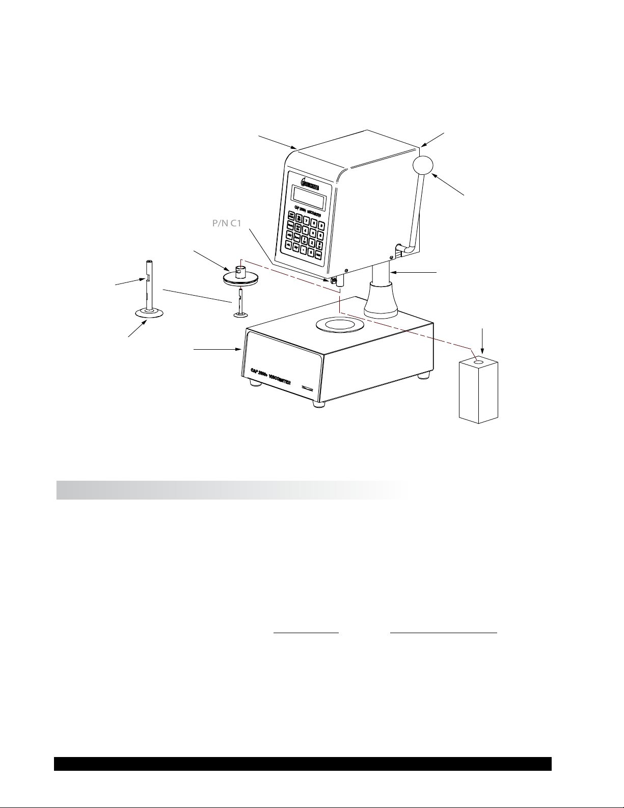
Please check to be sure that you have received all components and that there is no damage.
Handle for Raising
and Lowering
Viscometer Head
Solvent Trap
P/N C1K-63
Column
Head
Serial Tag Info
on Back of
Viscometer Head
Base
Console
Cone Spindle
P/N CAP-S-XX
The Flat
Thumb Screw
P/N C1
P/N C1K-34Y
Foam Shipping Insert
P/N CAP-122
If you are missing any parts, please notify Brookeld or your local dealer immediately. Any
shipping damage must be reported to the carrier. Save the packing container, if possible, for
future use when returning the viscometer to Brookeld or an authorized dealer for service.
Figure I-1: Components
I.2 Utilities
Input Voltage: 115 VAC or 230 VAC
Input Frequency: 50/60 Hz
Power Consumption: Less than 345 WATTS
Fuses: (2) 5x20mm, 3A, 250V; Fast Acting for 125VAC
(2) 5x20mm, 1.6A, 250V; Fast Acting for 250VAC
Power Cord Color Code:
United States Outside United States
Hot (live) Black Brown
Neutral White Blue
Ground (earth) Green Green/Yellow
Brookeld Engineering Labs., Inc. Page 6 Manual No. M02-313-G0812
Page 7

I.3 Specications
Torque Range: Low 797-7,970 dyne
High 18,100-181,000 dyne
•cm (designated on serial tag as 1/23 CAP)
•cm (designated on serial tag as CAP)
Speeds: Variable speed from 5-1000 RPM
Temperatures: CAP 2000+L 5°C (or 15°C below ambient, whichever is higher) to 75°C
CAP 2000+H 50°C to 235°C
All models provide 0.1°C increments
Weight: Gross Weight 36 lb 16.3 kg
Net Weight 27 lb 12.3 kg
Carton Volume 4.9 cu ft 0.15 m
3
Carton Dimensions 18 in. L x 18 in. W x 26 in. H
48 cm. L x 48 cm. W x 66 cm. H
Materials: CAP cone spindles and temperature plates are made of tungsten carbide.
Solvent Trap (P/N C1K-63) is made of teon.
Operating CAP 2000+ Viscometers must be operated within the following
Environment: ambient temperatures: +5°C (41°F) to 40°C (104°F)
and humidity: 20% to 80% R.H. (non-condensing atmosphere)
Electrical Certications:
Conforms to CE Standards: BSEN 61326: Electrical equipment for measurement,
control and laboratory use - EMC
requirements.
NOTICE TO CUSTOMERS:
This symbol indicates that this product is to be recycled at an appropriate collection center.
Users within the European Union:
Please contact your dealer or the local authorities in charge of waste management on how to
dispose of this product properly. All Brookeld ofces and our network of representatives and
dealers can be found on our website: www.brookeldengineering.com.
Users outside of the European Union:
Please dispose of this product according to your local laws.
Brookeld Engineering Labs., Inc. Page 7 Manual No. M02-313-G0812
Page 8
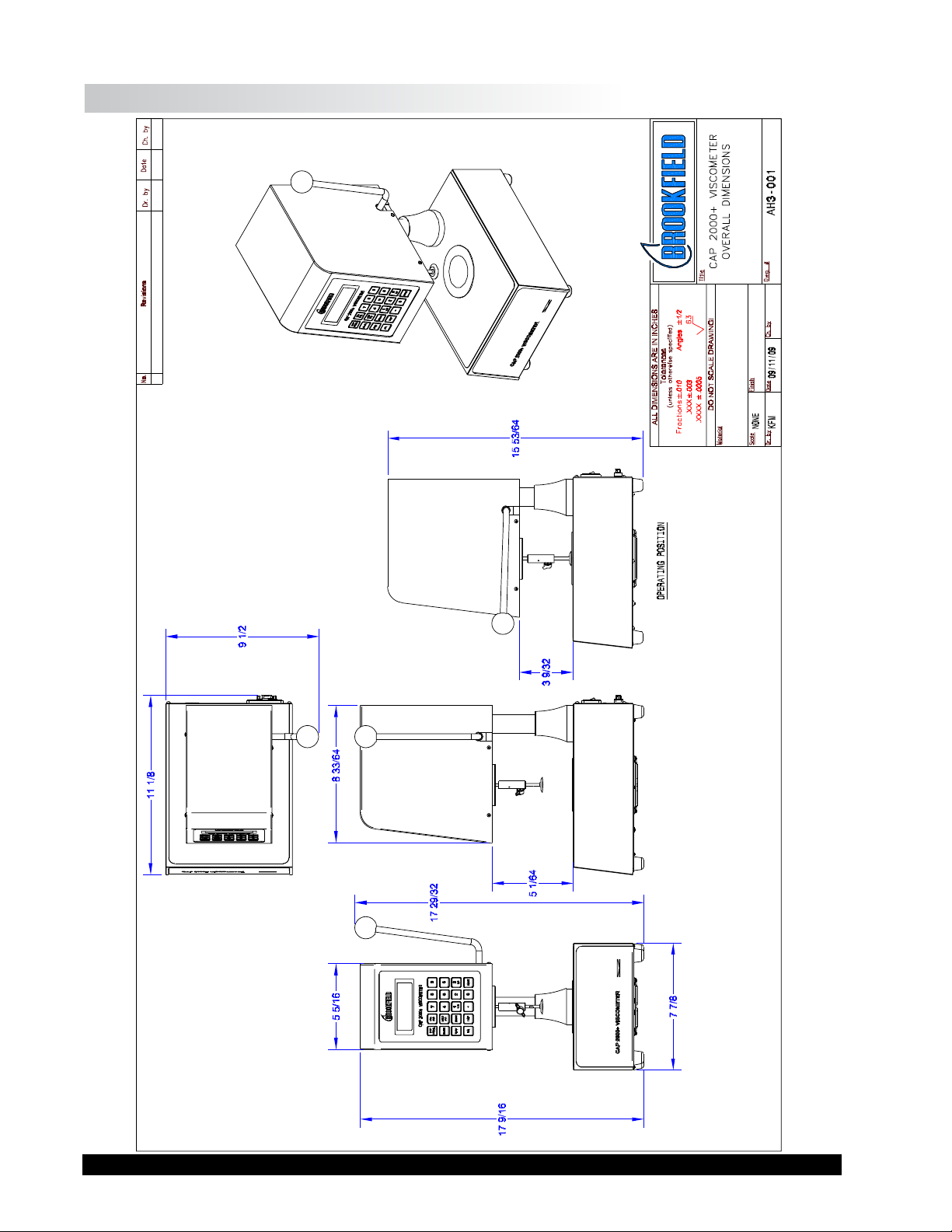
I.4 Dimensional Details
Brookeld Engineering Labs., Inc. Page 8 Manual No. M02-313-G0812
Page 9
I.5 Installation
DO NOT lift the viscometer by the handle or head! LIFT only by the base console or
column!
1) Set the viscometer on a clean level bench surface.
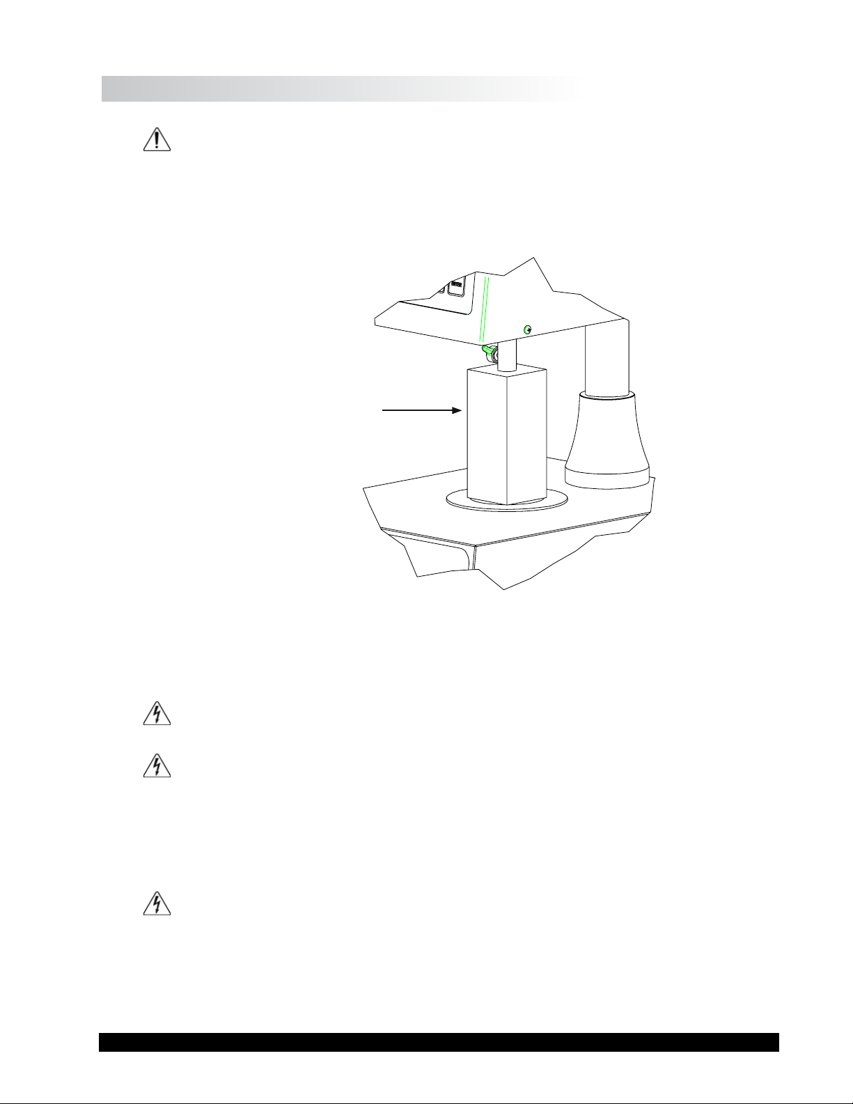
2) Remove shipping foam insert (P/N CAP-122) from the plate area on the CAP Viscometer.
Store the foam insert for future use when shipping or transporting CAP Viscometer.
Foam Insert Used
When Shipping
CAP Viscometer
Figure I-2: Detail of Foam Insert
3) Verify that the viscometer’s power requirements match your power source BEFORE
connecting it to power.
The AC input voltage and frequentcy must be within the appropriate range as shown
on the back of the viscometer head.
Note: The CAP Viscometer must be earth grounded. Use the three (3) wire power
cord! Do not alter!
4) Connect the power cord to the viscometer and to the power supply (source).
5) If using a printer, connect the printer cable to the printer port and printer.
Note: Ensure that both the printer and the CAP 2000+ are off when connecting cables.
Brookeld Engineering Labs., Inc. Page 9 Manual No. M02-313-G0812
Page 10
I.6 Safety Symbols and Precautions
Safety Symbols
The following explains safety symbols which may be found in this operating manual.
Indicates hazardous voltages may be present.
Caution: HOT surface.
Refer to the manual for specic warning or caution information to avoid personal injury
or damage to the instrument.
Safety Overview
If this instrument is used in a manner not specied by the manufacturer, the protection
provided by the instrument may be impaired.
This instrument is not intended for use in a potentially hazardous environment.
In case of emergency, turn off the instrument and then disconnect the electrical cord
from the wall outlet.
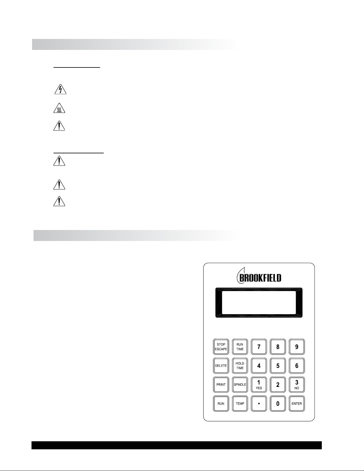
I.7 Key Functions
Figure I-3 shows the control keys on the face of the viscometer display panel:
NUMERIC 0 - 9
These keys are used for data entry
ENTER
This key accepts entered data.
STOP / ESCAPE
Stops cone spindle rotation at any time. Exits data
entry eld.
CAP 2000+ VISCOMETER
DELETE
This key clears entered values for input selections.
PRINT
This key sends data to the parallel printer.
RUN
This key starts spindle rotation.
RUN TIME
This key selects time entry mode (time of spindle
rotation).
Brookeld Engineering Labs., Inc. Page 10 Manual No. M02-313-G0812
Figure I-3
Page 11

HOLD TIME
This key selects time entry mode (wait time before spindle rotates).
SPINDLE
This key selects the cone spindle entry mode.
TEMP
This key selects the temperature entry mode.
I.8 Viscosity and Temperature Display
Viscosity is displayed in either P=Poise or cP=Centipoise (CGS system) or Pa•s=Pascal
seconds or mPa•s=milliPascal seconds (SI system). If the viscosity measurement is over
range, “EEEE” will be displayed. Brookeld recommends a minimum torque reading of 10%
when making viscosity measurements. If the torque value is between 0 and 10%, the display
will ash to indicate an under range condition. If the viscometer nal reading is below zero,
negative values will be displayed.
Temperature is displayed in °C=degrees centigrade.
I.9 Cleaning
Instrument, Keypad & Painted Surfaces:
Clean with dry, non-abrasive cloth. Do not use solvents or cleaners.
Immersed Components (spindles/cones) and temperature controlled plate:
Note: Sample plate and spindle may be hot. Use care when using solvents.
All immersed components are made of carbide steel. Clean with non-abrasive cloth and
solvent appropriate for sample material that is not aggressive to immersed components.
Do not use metal objects to clean the plate surface, as scratching of the plate may occur
and comporomise cone calibrations.
Solvent Trap:
Solvent Trap (P/N C1K-63) is made of Teon. Clean with non abrasive cloth and solvent
appropriate for sample material that is not aggressive to Teon.
Do not use metal objects to clean the plate surface, as scratching of the plate may
occur and compromise cone calibrations.
Immersed components (cone spindle) may be at an elevated temperature. Use caution
when cleaning hot surfaces. Use caution when applying solvents to hot surfaces. Refer
to the MSDS for the specic solvent for proper handling techniques.
Note: When cleaning, take care not to apply excessive force which may bend the spindle
shaft or otherwise damage the instrument.
Brookeld Engineering Labs., Inc. Page 11 Manual No. M02-313-G0812
Page 12

II. GETTING STARTED
II.1 Power On
Turn the power ON using the switch located on the rear of the base console.
The start-up screen will be displayed for four seconds and will indicate the viscometer model,
version number and torque range.
BROOKFIELD
CAP 2000+ VISCOMETER
VERSION 1.10
1.0 CAP
Figure II-1A Figure II-1B
Start-up Screen for High Torque CAP Start-up Screen for Low Torque CAP
CAP 2000+ VISCOMETER
BROOKFIELD
VERSION 1.10
22.7 CAP
After four (4) seconds, the main screen will be displayed (Figure II-2).
0.00P 0.0%
Run 15 Spindle 04
50.0C 900 RPM
Figure II-2
The instrument will be set to the default temperature:
CAP L Series Viscometer 25.0°C
CAP H Series Viscometer 50.0°C
If the CAP 2000+ Viscometer is connected to a PC via the serial port on the rear of the base
console, the main screen display is EXTERNAL.
Special Functions
Units of measure and speed control may be selected through the special functions screen. This
screen is accessed by pressing the STOP key during instrument power up.
The CAP 2000+ can be congured to control speed by either rotations per minute (RPM) or
shear rate (1/SEC). This selection is set by choosing 1=SPEED CONTROL in the special func-
tions screen, then selecting 1=RPM or 2=1/SEC and pressing ENTER.
The CAP 2000+ can be congured to display viscosity in one of four units: Poise (P), Centipoise
(cP), Pascal Seconds (Pa•s) or milliPascal seconds (mPa•s). This selection is set by choos-
2=Units of Measure in the special functions screen, selecting 1=P, 2=cP, 3=Pa•s, or
ing
4=mPa•s, and then pressing ENTER.
Once the CAP 2000+ has been congured, the instrument must be turned OFF. The congura-
tion will be stored in memory.
Note: When operating the CAP 2000+ with shear rate as the method of speed control,
the shear rate value entered may be adjusted based on the shear rate multiplier
for the spindle. For example: if using cone 4 (shear rate multiplier of 3.33), an
entered shear rate of 51 1/SEC will be displayed as 50 1/SEC.
Brookeld Engineering Labs., Inc. Page 12 Manual No. M02-313-G0812
Page 13

II.2 Cone Spindle Selection and Setting
Raise the viscometer handle to its highest position.
The CAP cones have viscosity ranges as shown in Tables III-1 and III-2. After selecting the appropriate cone for the viscosity range to be utilized, carefully attach the cone to the viscometer
as shown in Figure II-3.
Be sure to insert the spindle completely into the adapter sleeve; align the at (see Figure I-1)
on the spindle with the thumb screw and then tighten.
When using the solvent trap (Figure II-3), connect it to the cone adapter by sliding it up, passing
the slot by the thumb screw and turning the trap clockwise onto the thumbscrew. Slide the cone
up into the adapter as far as it will go and hand lock it in place with the thumb screw. Tighten
the thumb screw rmly and securely.
Thumb Screw
Solvent Trap
Figure II-3: Cone Attachment
Cone Spindle
Press the SPINDLE key. The display will change to the spindle entry screen. Using the number
keys, type in the required spindle number.
Two digits must be entered for the cone number. For cone 01 through 09, the rst number
remains as “0”.
Note: The default cone setting on power-up will be the last cone entry prior to shutting
off the viscometer.
After the correct two (2) digits have been entered, press the ENTER key and the cone will be
accepted for viscometer calculations. The screen will display the following message:
Brookeld Engineering Labs., Inc. Page 13 Manual No. M02-313-G0812
Page 14

Spindle 04
CALIBRATE? YES/NO
Figure II-4
If you are using the CAP Viscometer for the rst time or have just received the instrument back
from being serviced, press YES and see Section III. Cones supplied at the time of order are
calibrated to the viscometer by Brookeld prior to shipment, but should still be veried with a
calibration check prior to use for the rst time. Cones purchased separately at a later time by
the user must also be calibrated prior to making viscosity measurements. If you have 2 cone
spindles that are identical (have the same number), you must do a cone calibration when you
swap them.
Otherwise, there is no requirement to perform a cone calibration (Select NO).
Note: 1. CAP Viscometers allow for only one cone at a time of the same cone number
to be calibrated to the viscometer. Multiple cones of the same cone number must
each be calibrated to the viscometer before operation (Refer to Section III).
2. A special feature of the CAP series viscometers allows the user to perform a
cone calibration with viscosity standard uids. (Refer to Section III.4)
3. Cones entered as 11 through 99 must be rst calibrated following the directions
in Section III.
If you are not going to calibrate the cone, continue by pressing the NO key, then the ENTER key.
The viscometer will display the MAIN SCREEN (Figure II-2). Should you subsequently run
a test and observe that the instrument is reading all “0s”, the “P” for Poise is ashing, and the
“%” symbol is ashing, then the cone spindle you are using is not calibrated. You must perform
the cone spindle calibration to rectify the problem.
If you are going to calibrate the cone, press the YES key, and follow the calibration instructions
in Section III.4 - Cone Calibration.
II.3 Speed Setting
The CAP 2000+ is a variable speed viscometer. The speed of rotation is shown in the lower
right corner of the display. To change the speed of rotation, enter the new speed using the
number keys. The new speed will be shown in the lower right hand corner of the display. To
accept the new speed, press ENTER.
The new speed may be cancelled by pressing ESCAPE before pressing ENTER.
To begin spindle rotation, press the RUN key.
Note: The speed cannot be changed while the motor is running.
Speed control may be congured to either shear rate or rotations per minute (see Special
Functions in Section II.1). Data entry for speed selection is the same in either conguration.
Data entry must be in whole numbers.
Brookeld Engineering Labs., Inc. Page 14 Manual No. M02-313-G0812
Page 15

II.4 Temperature Control Setting
Press the TEMP key and the current temperature setting will blink. The default temperature on
start-up is 25.0°C on low temperature models and 50.0°C on high temperature models.
The temperature ranges are:
Low temperature: 5°C (or 15°C below ambient, whichever is higher) to 75°C
High temperature: 50°C to 235°C
Use the number keys to type in the required set point. The temperature can be set in increments
of 0.1°C. You can turn off the temperature control on a high temperature unit by entering 0.
Use the ENTER key to accept the new set point.
Note: Thermal equilibrium of the sample and of the spindle must be considered for best
measurement results. Upon powering up the Viscometer or after changing the
temperature set point, allow sufcient time for the plate to reach the desired temperature. It is recommended to have the spindle in contact with the plate prior to
introducing the sample material to ensure that the spindle is also at the temperature
of test. Brookeld recommends using the solvent trap at all times to enhance the
temperature control of the sample material. After inserting the sample material onto
the plate, lower the spindle and solvent trap and allow sufcient time for thermal
equilibrium prior to starting the test.
II.5 Hold Time Settings
Hold Time sets the time period between when the RUN TIME key is pressed and when the spindle
begins to rotate. This time period is normally used to ensure thermal equilibrium of the sample
and spindle. The hold time range is 0 to 999 seconds.
Press the HOLD TIME key and the current hold time will blink on the default screen. Use the
number keys to type in the required hold time and press the ENTER key.
Note: When the hold time is set to zero, it is not displayed on the default screen. Run time
will be shown on the default screen only when hold time is set to zero.
Note: With a run time of zero, the hold time will not be used
II.6 Run Time
Run Time sets the time period of spindle rotation. The run time range is 0 to 999 second.
Press the RUN TIME key and the current run time will blink on the default screen. Use the
number keys to type in the required run time and press the ENTER key.
A Run Time of zero sets the viscometer to innite run mode. In this mode, the spindle will
rotate at the set speed for as long as the RUN TIME key is pressed. The display will shown
“MANUAL”. When the RUN TIME key is released, the spindle will stop rotating.
Brookeld Engineering Labs., Inc. Page 15 Manual No. M02-313-G0812
Page 16

Note: With a run time of zero, the hold time will not be used
The time required for reading stabilization will depend on the speed of rotation and the nature
of the test sample. Longer runs times are recommended at lower speeds.
Speed Run
50-1000 RPM 12 seconds
20-50 RPM 20 seconds
5-20 RPM 30 seconds
II.7 Printing
Pressing the PRINT key at any time sends information on test parameters to the printer port.
Note: Calculated parameters (Viscosity, Full Scale Range, Shear Stress) will be displayed
only after the spindle has rotated sufciently to allow for accurate data. If print is
pressed before these parameters are displayed, then no data will be included in the
print string.
To print a heading, press and hold the STOP/ESCAPE key and press the PRINT key. Then start
the test by pressing the RUN key. Press the PRINT key whenever data is desired during the test.
Example of CAP 2000+ PRINT OUTPUT showing heading and data.
VISCOSITY
(POISE)
- - 25.0 - 10000 0750 20 02
F.S.R.
(%)
TEMP
(Deg C)
A maximum value of 999 seconds can be printed in the time column when running in manual
TIMER mode (00). Over 999 seconds will print EEEE.
The TIMER (SEC) column will indicate the accumulated time of running at the moment the
print key is pressed while the cone is rotating. This time value will not include the hold time.
At the end of a test, data will automatically be sent to the printer port.
II.8 Run and Stop Keys
The RUN key has three functions:
1. Press RUN to begin a test.
2. Press and hold the RUN key for continuous rotation when 00 is the run time setting.
3. Used in executing a cone calibration.
S.STRESS
(D/CM2)
Figure II-5
S.RATE
(1/sec)
SPEED
(RPM)
TIMER
(SEC)
CONE
No.
The STOP key has three functions:
1. Stops the cone rotation at any time.
Brookeld Engineering Labs., Inc. Page 16 Manual No. M02-313-G0812
Page 17

2. Pressing and holding the STOP/ESCAPE key during power up selects the special func-
tions mode where the viscosity display units and speed of rotation may be changed.
(Section II.1)
3. Pressing and holding the STOP and PRINT keys simultaneously executes the printing of
a new heading (Section II.7).
II.9 Parameter Display
The parameter display will appear, as shown in Figure II-6, immediately after the RUN key is
pressed. All relevant measurement parameters will be shown for 5 seconds including speed,
shear rate, run time, hold time and spindle. The display will return to the default screen after
ve seconds.
Note: The viscometer will be operating according to the selected parameters while the
parameter display screen is shown.
Speed 15 RPM
Shear Rate 50 1/sec
Run 20 S Hold 10S
Spindle 04
Figure II-6
Brookeld Engineering Labs., Inc. Page 17 Manual No. M02-313-G0812
Page 18

III. OPERATION
The CAP 2000+ Viscometer rotates a precisely machined cone spindle over a temperature
controlled plate shearing the test sample over a range of speeds from 5 to 1000 RPM. This
provides a comprehensive capability to analyze materials for viscosity behavior as a function
of both shear rate and temperature. Tests can be run in standalone mode or under PC control.
This chapter explains how to use the CAP 2000+ toward these objectives.
III.1 Full Scale Range and Accuracy of Measurement
Full Scale Range (FSR) viscosity is the maximum viscosity that can be measured and occurs
when the % torque is 100. Brookeld recommends that viscosity measurements be made be-
tween 10 and 100% torque.
There are two tables to consult for viscosity range information, depending on which torque
model viscometer you purchased. To determine which torque model you have, consult the se-
rial tag of your viscometer or the certicate of calibration that accompanied the instrument or
the display on power up.
23CAP 2000+ = Low Torque CAP 2000+ = High Torque
Full Scale Range (FSR) is based on the cone spindle your are using, the torque model of your
viscometer, and the speed of spindle rotation. The tables below provide information on FSR
by torque model for the most common factory set speeds:
Table III-1: Full Scale Range Viscosity for LOW TORQUE CAP 2000+ Viscometer
Cone
Number
01 1875 13.33N 0.83 0.17 1875/(22.7*N)
02 3750 13.33N 1.65 0.33 3750/(22.7*N)
03 7500 13.33N 3.30 0.66 7500/(22.7*N)
04 15000 3.33N 6.61 1.32 15000/(22.7*N)
05 30000 3.33N 13.22 2.64 30000/(22.7*N)
06 75000 3.33N 13.04 6.61 75000/(22.7*N)
07 3150 2N 1.39 0.28 3150/(22.7*N)
08 12500 2N 5.51 1.10 12500/(22.7*N)
09 50000 2N 22.03 4.41 50000/(22.7*N)
10 5000 5N 2.20 0.44 5000/(22.7*N)
Cone Constant
Range
Shear Rate
Constant
FSR Poise at
100 RPM
FSR Poise at
500 RPM
FSR Poise at
any RPM
N= RPM
Poise x 100 = centiPoise
Brookeld Engineering Labs., Inc. Page 18 Manual No. M02-313-G0812
Page 19

Table III-2: Full Scale Range Viscosity for HIGH TORQUE CAP 2000+ Viscometer
Cone
Number
01 1875 13.33N 18.75 4.69 2.50 2.08 1875/(N)
02 3750 13.33N 37.50 9.38 5.00 4.17 3750/(N)
03 7500 13.33N 75.00 18.75 10.00 8.33 7500/(N)
04 15000 3.33N 150.00 37.50 20.00 16.67 15000/(N)
05 30000 3.33N 300.00 75.00 40.00 33.33 30000/(N)
06 75000 3.33N 750.00 187.50 100.00 83.33 75000/(N)
07 3150 2N 31.50 7.88 N/A* N/A* 3150/(N)
08 12500 2N 125.00 31.25 N/A* N/A* 12500/(N)
09 50000 2N 500.00 125.00 N/A* N/A* 50000/(N)
10 5000 5N 50.00 12.50 6.67 5.56 5000/(N)
Cone
Constant
Range
Shear
Rate
Constant
FSR Poise
at
100 RPM
FSR Poise
at
400 RPM
FSR Poise
at
750 RPM
FSR Poise
at
900 RPM
FSR Poise
any RPM
N= RPM
Poise x 100 = centiPoise
*Use of this cone at this RPM is not recommended
You can also determine FSR for any speed selection that is not in the above tables by doing a
simple calculation:
• For Low Torque CAP instruments:
Cone range constant / (22.7 * N) = FSR (Poise) where N = RPM
• For High Torque CAP instruments:
Cone range constant / N = FSR (Poise) where N = RPM
at
The last column in the above tables shows this calculation.
III.2 Accuracy of Viscosity and Temperature
The following tables indicate the accuracy of the viscosity measurement for the CAP 2000+
Viscometer using CAP spindles 01-10. This accuracy depends on both the rotational speed of the
cone and the percent of Full Scale Range (%FSR) in Poise at which the viscosity is measured.
Accuracy is stated in Poise (P) and is calculated as a % of the FSR viscosity.
To calculate accuracy:
• Determine FSR viscosity in Poise for the torque model, cone spindle, and speed of rotation,
using the information in Tables III-1 or III-2.
• Find the column that best denes the speed of rotation used for the measurement and your
reported % FSR from the measurement.
• Consult the table below to determine the accuracy of your measurement.
• Multiply the accuracy by the FSR viscosity if you need your accuracy stated in Poise.
Brookeld Engineering Labs., Inc. Page 19 Manual No. M02-313-G0812
Page 20

Table III-3: Accuracy for LOW TORQUE CAP 2000+ Viscometer
Cone Number ≤ 500 RPM
10-100% FSR
01 ± 2%
02 ± 2%
03 ± 2%
04 ± 2%
05 ± 2%
06 ± 2%
07 ± 2%
08 ± 2%
09 ± 2%
10 ± 2%
Table III-4: Accuracy for HIGH TORQUE CAP 2000+ Viscometer
Cone Number ≤ 400 RPM 750 RPM 900 RPM 900 RPM
10-100% FSR 10-100% FSR ≤ 50% FSR > 50% FSR
01 ± 2% ± 2% ± 2% ± 4%
02 ± 2% ± 2% ± 2% ± 4%
03 ± 2% ± 2% ± 2% ± 4%
04 ± 2% ± 3% ± 3% ± 6%
05 ± 2% ± 4% ± 4% ± 8%
06 ± 2% ± 5% ± 5% ± 10%
07 ± 2% N/A* N/A* N/A*
08 ± 2% N/A* N/A* N/A*
09 ± 2% N/A* N/A* N/A*
10 ± 2% ± 2% ± 2% ± 2%
* Use of this cone at this RPM is not recommended.
The specication of temperature accuracy on CAP Viscometers is stated below:
LOW TEMP UNITS:
• In ambient conditions of 15°C to 30°C, tmperature accuracy is +/- 0.5°C.
• In ambient conditions of 5°C to 15°C or 30°C to 40°C, temperature accuracy is +/- 1.0°C.
HIGH TEMP UNITS:
• In ambient conditions of 15°C to 30°C, accuracy is +/- 0.5°C when the temperature set point
on the viscometer is 50°C to ≤100°C.
• In ambient conditions below 15°C or above 30°C, accuracy is +/- 2.0°C when the temperature
set point on the viscometer is 50°C to ≤100°C.
• In ambient conditions of 15°C to 30°C, accuracy is +/- 1.0°C when the temperature set point
on the viscometer is 101°C to 235°C.
Brookeld Engineering Labs., Inc. Page 20 Manual No. M02-313-G0812
Page 21

III.3 Calibration Verication
Accuracy of the CAP 2000+ Viscometer can be veried by performing a calibration verication.
Go to www.brookeldengineering.com to view a video on the procedure.
The cones/spindles that were shipped with the viscometer were calibrated to the viscometer by
Brookeld prior to shipment. If your viscometer was returned to Brookeld or an authorized
Brookeld Dealer, then any cones/spindles that were returned for service will have been
calibrated to the viscometer prior to shipment.
When you receive the instrument, perform a calibration verication on each cone spindle to
ensure that each spindle is measuring correctly. Use the appropriate viscosity standard uid
dened in Table III-5 or III-6 for each spindle. This will ensure that everything is in good
working order and that the instrument and/or cone spindles have not experienced a change
during shipment. If the calibration verication fails then you can take advantage of the CAP
Viscometer’s unique feature which allows the operator to recalibrate each cone spindle to the
CAP Viscometer (See Section III.4).
Calibration verication of your viscometer should also be performed when viscosity readings
with your product are suspect. Verifying the calibration will determine if the cone needs to
be recalibrated to the instrument. This will help you to determine if the discrepant readings
on your product are due to cone/instrument performance, or your method or your product.
Complete cone recalibration is discussed in Section III.4.
To perform a cone calibration verication, you will need a mineral oil from Table III-5 or Table
III-6. Determine what range model CAP 2000+ Viscometer you have (Low Torque or High
Torque), which temperature range (L = Low, H = High; consult the instrument serial tag) and
what cone your are using.
You must use the following method to verify calibration of each cone spindle.
1. Attach solvent trap and spindle and lower viscometer head. Put the cone in the down
position, and make sure that the solvent trap is covering the spindle.
2. Allow the viscometer to stabilize for at least 30 minutes at 25°C (Low Temp units) or at
60°C (High Temp) if the temperature that you normally operate is different; otherwise, wait
5 minutes, then make sure the cone is in the down position and that the solvent trap is on.
3. At the end of the temp stabilization period, dispense the appropriate volume of uid (consult
Table III-5 or Table III-6). Figure III-1 shows how to dispense the uid onto the plate and
determine visually if the amount is appropriate.
Brookeld Engineering Labs., Inc. Page 21 Manual No. M02-313-G0812
Page 22

Figure III-1a Figure III-1b
Figure III-1c Figure III-1d
4. Run a viscosity test and record the viscosity value when the reading has stabilized.
5. Compare the recorded viscosity to the actual value of the standard and verify that it falls
within the accuracy limits stated in Tables III-3 and III-4. The allowable accuracy is
calculated by adding 1% of the value for the viscosity standard uid to the product of (%
accuracy x FSR) for the spindle/speed in use. This combined value (in Poise or cP) gives
an allowable window around the actual viscosity value of your standard. If your measured
viscosity falls within this window, the verication passes.
Example:
CAP-03 spindle on High Torque Low Temp CAP Viscometer running at 900 RPM.
Viscosity standard has nominal value at 25ºC of 354 cP or 3.54 P; 1% = 3.54 cP or
0.0354 P. FSR = 8.33 P from Table III-2; use 2% accuracy calculation from Table III-4
since viscosity standard < 50% of FSR. Accuracy for viscometer with CAP-03 spindle
is therefore 2% X 8.33 P = 0.1666 P. Add 0.0354 P to 0.1666 P to determine the allowable accuracy ± 0.2020 P. The measured viscosity value with CAP-03 spindle must be
within ± 0.202 P or 20.2 cP of the viscosity standard to pass calibration.
6. If the test fails, repeat again to make sure that every step was performed correctly. If the
test fails again, perform a cone calibration according to the procedure in Section III.4.
Brookeld Engineering Labs., Inc. Page 22 Manual No. M02-313-G0812
Page 23

Table III-5: Viscosity Standard Fluids for Calibration of CAP Spindles on LOW TORQUE CAP 2000+ Viscometer
LOW
TORQUE
Cone
CAP-S-01 CAP0L 57 25 67 CAP-S-01 CAP0H 57 60 67
CAP-S-02 CAP1L 89 25 38 CAP-S-02 CAP1H 89 60 38
CAP-S-03 CAP2L 177 25 24 CAP-S-03 CAP2H 177 60 24
CAP-S-04 CAP3L 354 25 124 CAP-S-04 CAP3H 354 60 124
CAP-S-05 CAP4L 708 25 67 CAP-S-05 CAP4H 708 60 67
CAP-S-06 CAP5L 1417 25 32 CAP-S-06 CAP5H 1417 60 32
CAP-S-07 CAP1L 89 25 1700 CAP-S-07 CAP1H 89 60 1700
CAP-S-08 CAP3L 354 25 400 CAP-S-08 CAP3H 354 60 400
CAP-S-09 CAP5L 1417 25 100 CAP-S-09 CAP5H 1417 60 100
CAP-S-10 CAP2L 177 25 170 CAP-S-10 CAP2H 177 60 170
Table III-6: Viscosity Standard Fluids for Calibration of CAP Spindles on HIGH TORQUE CAP 2000+ Viscometer
HIGH
TORQUE
Cone
CAP-S-01 CAP1L 89 25 67 CAP-S-01 CAP1H 89 60 67
CAP-S-02 CAP2L 177 25 38 CAP-S-02 CAP2H 177 60 38
CAP-S-03 CAP3L 354 25 24 CAP-S-03 CAP3H 354 60 24
CAP-S-04 CAP4L 708 25 124 CAP-S-04 CAP4H 708 60 124
CAP-S-05 CAP5L 1,417 25 67 CAP-S-05 CAP5H 1,417 60 67
CAP-S-06 CAP6L 3,542 25 32 CAP-S-06 CAP6H 3,542 60 32
CAP-S-07 CAP7L 1,328 25 1700 CAP-S-07 CAP7H 1,328 60 1700
CAP-S-08 CAP8L 5,313 25 400 CAP-S-08 CAP8H 5,313 60 400
CAP-S-09 CAP9L 21,250 25 100 CAP-S-09 CAP9H 21,250 60 100
CAP-S-10 CAP10L 236 25 170 CAP-S-10 CAP10H 236 60 170
LOW
TEMP
Fluid
Part
Num-
ber
LOW
TEMP
Fluid
Part
Num-
ber
Nomi-
nal
Value
(cP)
Nomi-
nal
Value
(cP)
Temp
(°C)
Temp
(°C)
Sample
Size
(micro
liters)
Sample
Size
(micro
liters)
LOW
TORQUE
Cone
HIGH
TORQUE
Cone
HIGH
TEMP
Fluid
Part
Num-
ber
HIGH
TEMP
Fluid
Part
Num-
ber
Nomi-
nal
Value
(cP)
Nomi-
nal
Value
(cP)
Temp
(°C)
Temp
(°C)
Sample
Size
(micro
liters)
Sam-
ple
Size
(micro
liters)
III.4 Cone Calibration
A special feature of the CAP Series Viscometers allows the user to perform a cone calibration
using Viscosity Standard Fluids. This eld calibration will accommodate any wear on the tip
of the cone which may result from contact with the plate. This also allows the user to purchase
a new cone spindle and perform the calibration in your plant.
Brookeld Engineering Labs., Inc. Page 23 Manual No. M02-313-G0812
Page 24

Note: A cone calibration should be performed when: 1) using a new cone for the rst time,
2) switching between two cones of the same number and 3) verication of calibration
provides data outside of the acceptable range.
Refer to Tables III-5 and III-6 to choose the calibration uid for the spindle being calibrated.
1. Turn on the CAP 2000+ Viscometer.
2. Attach solvent trap to coupling shaft.
3. Attach spindle.
4. Place appropriate amount of sample onto the center of the Viscometer plate directly below
the spindle.
5. Pull down the handle, locking it into the lowest position, placing the spindle in contact with
the plate.
6. Lower the solvent trap.
Note: The solvent trap must be utilized when calibrating to ensure proper temperature control.
7. Select the spindle to be calibrated by using the SPINDLE key.
8. Select YES for CALIBRATE and press ENTER.
9. Enter the appropriate values for temperature (°C) and viscosity (cP) value printed on the
label.
Note: Viscosity values are always entered in units of CENTIPOISE (cP) no matter what units
have been selected as unit of measure for normal operation.
100 cP = 1P; 1cP = 1mPa•s; 1000 cP = 1Pa•s
Note: The Viscometer temperature control must be identical to the specied temperature for
the viscosity standard when executing the calibration. Normally calibration will be at
25°C for “L” Series CAP Viscometers and 60°C for “H” Series CAP Viscometers.
10. Allow at least 30 minutes for thermal equilibrium of the plate, calibration uid and spindle,
from instrument cold start.
11. Select the spindle speed.
All of the spindles used with the low torque CAP 2000+ instruments should be calibrated
at 100 RPM when using the recommended viscosity standard uids. This practice will
calibrate the instrument at approximately the middle of the Full Scale Range.
Spindles used with the high torque CAP 2000+ and the recommended viscosity standard
uids may be calibrated at any speed.
12. Press the RUN key to start the calibration.
Brookeld Engineering Labs., Inc. Page 24 Manual No. M02-313-G0812
Page 25

Note: The calibration process may be cancelled at any time prior to pressing RUN by press-
ing the ESCAPE key.
When calibration is complete, spindle rotation will stop and the “CALIBRATION COMPLETE”
screen is displayed. (See Figure III-2). Press ENTER to continue.
CALIBRATION COMPLETE
PRESS ENTER TO CONTINUE
If the viscometer is connected to a printer, the display will show “Press Print or Press Enter to
continue”. Press the PRINT key and the printout (Figure III-3) will automatically be generated.
There will be values for the listed variables. The operator can enter the information by hand
on the bottom of the printout.
CONE (00) CALIBRATION
VISCOSITY
(POISE)
Operator: ________________________________________________
Date: ____________________________________________________
Model/Serial #: ____________________________________________
Fluid: ____________________________________________________
FSR
(%)
TEMP
(Deg C)
S.STRESS
2
D/CM
)
S.RATE
(1/sec)
Figure III-3
SPEED
(RPM)
III.5 Repeatability
The CAP 2000+ Viscometer is repeatable to ±0.5% of the full scale viscosity range (FSR). Due
to shear heating considerations which occur in high shear rate instrumentation, the measurement
of NIST Viscosity Standard Fluids at rotational speeds above 900 RPM will show a decrease
in viscosity with an increase in rotational speed (shear rate).
TIMER
(SEC)
CONE
No.
SAMPLE
No.
Normal forces due to the shearing of a viscoelastic uid (such as paint) are accounted for in
the CAP Series Viscometers by weight on the spindle column of 3.4 Newtons (340,000 Dynes)
total force. This is done to avoid having the cone lift off the plate, thereby changing the cone
plate geometry and producing incorrect viscosity readings. For normal forces greater than
3.4 Newtons (340,000 Dynes) total force, additional externally mounted weights are required.
However, more weight means more wear on the cone and plate. Additional weights should
only be considered when denitely required and removed when not required.
Contact Brookeld Engineering Laboratories or your Brookeld Dealer/Distributor/Representa-
tive for details on the above information.
Brookeld Engineering Labs., Inc. Page 25 Manual No. M02-313-G0812
Page 26

III.6 Making Viscosity Measurements
The following procedure is recommended for making a viscosity measurement.
With the viscometer on a clean, level surface, connect it to the proper power supply (Section I.4).
1. Turn the power switch ON (Section II.1).
The procedure assumes that the following have been done:
a) If the viscometer has been “off” for an extended period (i.e., overnight) a “warm up”
period of 30 minutes is suggested. You may choose to warm up at the temperature of test.
If a cone calibration is to be done immediately after the warm up period, temperature
should be set to 60°C (calibration temperature for high temperature instruments) or 25°C
for low temperature instruments to save some time.
b) The cone calibration procedure should have been done for all cones which are used with
the instrument. Cone calibration is only required when a new cone (i.e., replacement
for lost/damaged cone) is used, or when calibration check fails.
c) When making measurements with low temperature instruments (CAP 2000+L), the
solvent trap may not be required (for the containment of solvents and/or prevention of
sample “drying”). The trap should be used for all measurements with high temperature
instruments (CAP 2000+H).
d) If a printer is to be used, it should be connected (AC power & viscometer to printer
cable). The CAP 2000+ will print automatically when a reading is taken if the printer
is connected and “on line.”
2. Select and attach the cone (Section II.2).
Notes: a. Lock the cone tightly into the adapter.
b. When measuring volatile samples such as paints and coatings, and when
using either a high temperature CAP 1000+H or CAP 2000+H, the solvent
trap must be put in place over the cone to prevent the test sample from
drying out during the rotation of the cone.
3. Set the temperature control (Section II.5).
4. Set the cone number.
5. Lower the handle placing the cone onto the plate. Lock the handle into its lowest position.
Drop the solvent trap over the cone.
Note: Allow ten (10) minutes for the cone to come to equilibrium temperature with the plate.
6. Secure trap on shaft. Caution: Solvent trap may be hot, spindle & plate too.
Raise the handle. Place the sample to be measured onto the plate below the cone
and solvent trap. Don’t use plastic spatulas/syringes if the plate temperature is above
50°C. Refer to Table III-5 or III-6 for recommended sample sizes. Lower the cone
and solvent trap.
Brookeld Engineering Labs., Inc. Page 26 Manual No. M02-313-G0812
Page 27

Notes: a. Lower the handle gently. DO NOT FORCE THE CONE ONTO THE
PLATE.
b. The sample must completely cover the face of the cone and extend beyond the
edge of the cone about 1.0 mm (see Figure III.3).
c. Release the solvent trap placing it onto the plate over the cone so it does not
touch the cone shaft.
The user should ensure that the substances placed under test do not release poisonous,
toxic or ammable gases at the temperatures to which they are subjected to during the
testing.
7. Allow the cone, plate and sample to equilibrate to the temperature control setting.
Note: A minimum of one (1) to three (3) minutes equilibrium time is recommended,
depending upon the sample.
8. Set the Run Time for rotating the cone (Section II.6) and the Hold Time.
9. Put the printer on-line (optional, Section II.7).
10. Press the RUN key and execute the viscosity measurement.
Note: Due to the dynamics of shearing a uid in the CAP “H” series Viscometers, the temperature
display may indicate a deection from the equilibrium temperature setting as the cone
begins rotating at high shear rates. The temperature display may indicate the temperature
of the plate and the momentary changes show the cycling of the temperature control at
high temperature. The precision of the viscosity measurement is maintained within the
limits specied in Table III.1.
11. Read the results of the sample test on the printer or write down the test conditions and
viscosity results from the viscometer display.
12. Relocate the solvent trap onto the cone adapter and raise the handle. Caution: HOT
surface!
13. It is recommended to remove the cone for cleaning. However, with care, the cone
can be cleaned in place. Caution: HOT surface!
14. Clean the viscometer plate (refer to Section I.8). Caution: HOT surface!
III.7 Computer Control
The CAP 2000+ Viscometer can be operated remotely under PC control when using the
CAPCALC application software.
Brookeld Engineering Labs., Inc. Page 27 Manual No. M02-313-G0812
Page 28

When advanced sample analysis is required, Brookeld CAPCALC application software can
control the CAP 2000+ Viscometer from a PC. CAPCALC for Windows requires Windows
Windows NT or higher. CAPCALC application software displays, prints and stores tabulated
data les (Brookeld, Excel).
CAPCALC software has automatic data capture (up to 200 data points per test) and graphical
data display (rheograms) to facilitate analysis of test samples. The software also allows
temperature control of the sample plate for integrated viscosity/temperature tests between 5°C
and 75°C (CAP 2000+L) or 50°C and 200°C (CAP 2000+H) depending on viscometer model.
CAPCALC features include on-screen and printed plots of % F.S.R., viscosity or shear stress vs.
cone speed, shear rate, time or temperature. Also available are automatic calculation of Yield
Stress (Bingham Plastic or Casson) and Power Law Consistency Index.
Additional information on the communications protocol for CAP 2000+ is contained in
Appendix B.
Contact Brookeld or our authorized agent to obtain the CAPCALC software program.
Brookeld Engineering Labs., Inc. Page 28 Manual No. M02-313-G0812
Page 29

APPENDIX A - Variables in Viscosity Measurements
As with any instrument measurement, there are variables that can affect a Viscometer
measurement. These variables may be related to the instrument (Viscometer), or the test uid.
Variables related to the test uid deal with the rheological properties of the uid, while instrument
variables would include the Viscometer design and the spindle geometry system utilized.
Rheological Properties
Fluids have different rheological characteristics that can be described by Viscometer
measurements. We can then work with these uids to suit our lab or process conditions.
There are two categories of uids:
Newtonian - These uids have the same viscosity at different Shear Rates (different
RPMs) and are called Newtonian over the Shear Rate range they are
measured.
Non-Newtonian - These uids have different viscosities at different shear rates (different
RPMs). They fall into two groups:
1) Time Independent non-Newtonian
2) Time Dependent non-Newtonian
The time dependency is the time they are held at a given Shear Rate (RPM). They are nonNewtonian, and when you change the Viscometer spindle speed, you get a different viscosity.
Time Independent
Pseudoplastic - A pseudoplastic material displays a decrease in viscosity with an increase in
shear rate, and is also known as “shear thinning”. If you take Viscometer
readings from a low to a high RPM and then back to the low RPM, and
the readings fall upon themselves, the material is time independent
pseudoplastic and shear thinning.
Time Dependent
Thixotropic - A thixotropic material has decreasing viscosity under constant shear rate.
If you set a Viscometer at a constant speed, recording P values over time,
and nd that the P values decrease with time, the material is thixotropic.
The Brookeld publication “More Solutions to Sticky Problems” includes a more detailed
discussion of rheological properties and non-Newtonian behavior.
Brookeld Engineering Labs., Inc. Page 29 Manual No. M02-313-G0812
Page 30

Viscometer Related Variables
• Most uid viscosities are found to be non-Newtonian. They are dependent on shear rate and
the spindle geometry. The specications of the Viscometer cone and plate geometry will affect
the viscosity readings. For example, if one reading is taken at 750 rpm, and a second at 900
rpm, the two viscosity values may be different because the readings were made at different
shear rates. The faster the spindle speed, the higher the shear rate.
• The shear rate of a given measurement is determined by the rotational speed and the cone
angle.
• A repeatable viscosity test should control or specify the following:
1. Viscometer model
2. Cone Spindle used: Cone Angle and Cone Diameter
3. Test temperature
4. Cone Spindle speed [or the shear rate]
5. Length of time to rotate cone spindle before recording the viscosity reading
6. Sample volume sufcient to cover the face of the cone
- Warranty Repair and Service
Brookeld Engineering Labs., Inc. Page 30 Manual No. M02-313-G0812
Page 31

APPENDIX B - Communications
External Control
Transmit Data (TxD)
Printer Output - CAP 2000+
The cable connection on the CAP 2000+ Viscometer is a standard 25 pin parallel printer cable
connector.
RS 232 Output - CAP 2000+
When connecting the CAP 2000+ to a computer, use Brookeld Computer Cable (Part No.
DVP-80). If you are not using the Brookeld computer cable, jump (connect) pins 4 and 9
(refer to Figure 1) on the CAP 2000 end of the serial cable. The cable connections are:
Com Port RxD (pin 2 (9 pin) or pin 3 (25 pin) to CAP Txd (pin 3)
Com Port TxD (pin 3 (9 pin) or pin 2 (25 pin) to CAP RxD (pin 2)
Com Port ground (pin 7) to CAP Serial Ground (pin 5)
The RS232 protocol is implemented as follows:
Baude rate: 9600
Parity: None
Data bits: 8
Stop bits: 1
The following pages review the transmit/receive commands between the CAP 2000+ and a
computer (Table 2), the byte status interpretation (Table 1) and a sample program for external
control of the CAP 2000+ Viscometer.
Serial Ground
External Control
45
3
89
2
No Connection to Pin 1
Figure 1
Receive Data (RxD)
1
67
Brookeld Engineering Labs., Inc. Page 31 Manual No. M02-313-G0812
Page 32

CAP 2000+ TRANSMIT/RECEIVE COMMANDS FOR COMPUTER COMMUNICATION
COMMAND
RECEIVED
Vyyy<CR> V<SS><CR> • Sets current speed and starts motor.
Tttt<CR> T<ss><CR> • Sets current temperature and controls to it.
R<CR> R<vvvvvvffffrrrrrrtttcc>
I<CR> ICAP+<bbxxxddddd
Scc<CR> Saaaaaaeeeeeecc
Invalid Command
Brookeld Engineering Labs., Inc. Page 32 Manual No. M02-313-G0812
CAP 2000 RESPONSE FUNCTION
• 000H <=yyy <=3E8H (t to 1000 RPM).
• Anything between 001H and 005H is interpreted as 5 RPM.
• Anything over 3E8H is interpreted as 1000 RPM.
• All yyy values shall be padded to 3 characters with leading zeros.
• A speed of 000 will stop the motor.
• Sets or clears the motor on bit (bit 1) in the status byte accordingly.
• Sets illegal value bit in status byte if yyy is outside limits (See Table 2).
• 032H <= ttt <= 2EEH; CAPLO (5°C to 75°C).
• 000H <= ttt <= 92EH; CAPHI (0°C to 235°C).
• Any temperature under the lower limit is interpreted as the lower limit.
• Any temperature over the upper limit is interpreted as the upper limit.
• The CAP 2000+ must divide all ttt values received by 10 before use.
• All ttt values shall be padded to 3 characters with leading zeros.
• Sets illegal value bit in status byte if ttt is outside limits (See Table 2).
• Returns a data packet to the host.
<ss><CR>
<ss><CR>
<ss><CR>
Kccvvvvvveeeeee
aaaaaayyy<ss><CR>
???<CR> • Invalid command received
• vvvvvv : viscosity ,P, (multiplied by 1000 by the CAP 2000+). All
vvvvvv values shall be padded to 6 characters with leading zeros.
• ffff: FSR ,%, (multiplied by 100 by the CAP 2000+). All ffff values
shall be padded to 4 characters with leading zeros.
• rrrrrr : shear rate , 1/seconds, (multiplied by 100 by the CAP 2000+). All
rrrrrr values shall be padded to 6 characters with leading zeros.
• ttt : temperature ,°C, (multiplied by 10 by the CAP 2000+). All ttt values
shall be padded to 3 characters with leading zeros.
• cc : cone. All cc values shall be padded to 2 characters with leading
zeros.
• Identify the viscometer and rmware in use.
• bb: HI or LO : temperature range.
• xxx : rmware version (decimal format) multiplied by 100.
• ddddd : spring constant, (multiplied by 10,000 by the CAP 2000+). All
ddddd values shall be padded to characters with leading zeros.
• Selects cone to be used.
• cc : cone #: All cc values shall be padded to 2 characters with leading
zeros.
• 01H<=cc<=14H; Any S command sent with a cone number outside these
limits will be ignored.
• Cone # outside limits: response values represent the cone the instrument
is staying with.
• aaaaaa : cone multiplier constant. All aaaaaa values shall be padded to 6
characters with leading zeros.
• eeeeee : shear rate constant of cone (multiplied by 10000). All eeeeee
values shall be padded to 6 characters with leading zeros.
• Sets illegal value bit in status byte if cc is outside limits (See Table 2).
• Calibrate a new cone.
• The response will not be returned to the host until the calibration is
complete.
• cc : cone #: All cc values shall be padded to 2 characters with leading
zeros.
• vvvvvv : viscosity of calibration uid (centipoise). All vvvvvv values
shall be padded to 6 characters with leading zeros.
• eeeeee : shear rate constant of cone. The CAP 2000+ divides all eeeeee
values by 10000 upon receiving them and multiplies by 10000 before
sending them. All eeeeee values shall be padded to 6 characters with lead-
ing zeros.
• aaaaaa : cone multiplier constant. All aaaaaa values shall be padded to 6
characters with leading zeros
• yyy : calibration speed. Subject to same limitations as in V command.
• If there is an error, bit 7 of the status byte is set.
Table 1
Page 33

Note: All multiplication and division operations performed on any of the command values
should be done while the values in question are in their decimal (base 10) form (i.e.
before any conversion to hexadecimal).
LEGEND
Command Description
<aaaaaa> Cone multiplier constant (hexadecimal). All cone multiplier constant values are six characters padded
with leading zeros.
<bb> (HI / LO) Indicates whether the instrument operates in the high (0°C to 235°C) temperature range or
the low (5°C to 75°C) temperature range.
<cc> Cone number (hexadecimal); all cone number are two characters padded with leading zeroes. All cone
values are two characters padded with leading zeroes.
<CR> Carriage return
<ddddd> Spring Constant (hexadecimal). The Spring Constant must be multiplied by 10,000 before transmis-
sion by the CAP 2000+. Use the base Spring Constant for the model, not an adjusted constant after
calibrating.
<eeeeee> Shear rate constant of a cone to be calibrated (hexadecimal). The CAP 2000+ must divide shear rate
constants by 10000 after they are received, and multiply shear rate constants by 10000 before sending
them out. All shear rate constant values are six characters padded with leading zeroes.
<ffff> % FSR (hexadecimal). % FSR values are multiplied by 100 before transmission from the CAP 2000+.
All FSR values are four characters padded with leading zeroes.
<rrrrrr> Shear rate (1/seconds) values (hexadecimal). Shear rate values are multiplied by 100 before transmis-
sion by the CAP 2000+. All shear rate values are six characters padded with leading zeroes.
<ss> Status byte, returned in hexadecimal format, see Table 2 for complete description. All status bytes are
two characters padded with leading zeroes.
<ttt> Temperature (°C) sent to or from the CAP 2000+ (hexadecimal). The CAP 2000+ must divide all tem-
perature values received by 10, and multiply all temperature values sent by 10. All temperature inputs
are three characters padded with leading zeroes.
<vvvvvv> Viscosity (P) sent to or from the CAP 2000+ (hexadecimal). The CAP 2000+ must divide all viscos-
ity values received by 1000, and multiply all viscosity values sent by 1000; all viscosity values are six
characters padded with leading zeroes.
<xxx> Firmware version number, in decimal format, multiplied by 100 by CAP 2000+ before transmission
(i.e. for rmware version 2.15, xxx would be 215).
<yyy> Speed (RPM) input (hexadecimal). All speeds are three characters padded with leading zeroes.
INTERPRETATION OF BYTE STATUS
Bit 7 Bit 6 Bit 5 Bit 4 Bit 3 Bit 2 Bit 1
Motor Off x x x x x x 0
Motor On x x x x x x 1
Over SFR (>=115.0%)
Valid FSR (<115.0%) x x x x x 0 x
Value Outside Limits
Value Within Limits x x x x 0 x x
Calibration Error 1
Brookeld Engineering Labs., Inc. Page 33 Manual No. M02-313-G0812
1
x x x x x 1 x
2
x x x x 1 x x
3
x x x x x x
Page 34

Example:
1. The CAP 2000+ has been turned on with the proper cable inserted in the serial port placing
2. The host computer sends an I. The CAP 2000+ responds with an ICAPHI2201000000,
3. The host sends a T190. The CAP 2000+ begins controlling to 40.0°C and responds with
4. The host sends V1F4. The CAP 2000+ ramps to 500 rpm and responds with V02 indicating
5. The host sends a T9C4. The request to control temperature to 250.0°C is illegal. The
6. The host sends an R. The CAP 2000+ responds with R002B1115950A25A83E80102
1
Bit 2 is set in response to an R command (request for information) only.
2
If an input is received that is outside the allowable limits for a command, Bit
3 shall be set for the response to that command only. Once the response to the
command has been sent to the host, Bit 3 shall be cleared again.
3
This bit is set in response to a calibration command if an error occurred in the
respective operation
Table 2
the unit in its external mode.
indicating a high temperature CAP 2000+ with Version 2.20 rmware, spring constant of
1.00, and a status byte of 0.
T100.
the motor is running.
CAP 2000+ responds with T0A indicating a temperature request outside the limits of the
instrument.
indicating a viscosity reading of 11.025 Poise, a FSR reading of 55.25%, a shear rate of
6650 1/sec, a sensed temperature of 100.0°C, and a number one cone. Note that Bit 3 of
the status byte has been cleared. It is set only in response to the offending command (T9C4)
and is cleared as soon as the response is issued.
Brookeld Engineering Labs., Inc. Page 34 Manual No. M02-313-G0812
Page 35

APPENDIX C - Online Help and Additional Resources
www.brookeldengineering.com**
The Brookeld website is a good resource for additional and self-help whenever you need it. Our
website offers a selection of “how-to” videos, application notes, conversion tables, instructional manuals,
material safety data sheets, calibration templates and other technical resources.
http://www.youtube.com/user/BrookeldEng
Brookeld has its own YouTube channel. Videos posted to our website can be found here as well as
other “home-made” videos made by our own technical sales group.
Viscosityjournal.com
Brookeld is involved with a satellite website that should be your rst stop in viscosity research. This
site serves as a library of interviews with experts in the viscosity eld as well as Brookeld technical
articles and conversion charts. Registration is required, so that you can be notied of upcoming interviews
and events, however, this information will not be shared with other vendors, institutions, etc..
Article Reprints
- Available in Print Only
- Brookeld has an extensive library of published articles relating to viscosity, texture and
powder testing. Due to copyright restrictions, these articles cannot be emailed. Please request
your hardcopy of articles by calling our customer service department directly or by emailing:
marketing@brookeldengineering.com
- Available Online
- Brookeld has a growing number of published articles that can be downloaded directly from
the Brookeld website. These articles can be found on our main site by following this path:
http://www.brookeldengineering.com/support/documentation/article reprints
More Solutions to Sticky Problems
Learn more about viscosity and rheology with our most popular publication. This informative booklet will
provide you with measurement techniques, advice and much more. It’s a must-have for any Brookeld
Viscometer or Rheometer operator. More Solutions is avaiable in print and also as a downloadable pdf
on the Brookeld website by following this path:
http://www.brookeldengineering.com/support/documentation
Training/Courses
Whether it is instrument-specic courses, training to help you better prepare for auditing concerns, or
just a better understanding of your methods, who better to learn from than the worldwide leaders of
viscosity measuring equipment? Visit our Services section on our website to learn more about training.
** Downloads will require you to register your name, company and email address. We respect your
privacy and will not share this information outside of Brookeld.
Brookeld Engineering Labs., Inc. Page 35 Manual No. M02-313-G0812
Page 36

APPENDIX D - Packing Instructions to Return a Brookeld CAP Viscometer for
Repair or Calibration
Brookeld Engineering Labs., Inc. Page 36 Manual No. M02-313-G0812
Page 37

APPENDIX E - Warranty Repair and Service
Warranty
Brookeld Viscometers are guaranteed for one year from date of purchase against defects in materials
and workmanship. They are certied against primary viscosity standards traceable to the National
Institute of Standards and Technology (NIST). The Viscometer must be returned to Brookeld
Engineering Laboratories, Inc. or the Brookeld dealer from whom it was purchased for warranty
service. Transportation is at the purchaser’s expense. Remove the spindle from the viscometer and
attach the shipping foam block (see Figure I-2) to prevent shipping damage. The Viscometer should
be shipped in the original packaging provided with the instrument along with any spindles that need
service. If returning to Brookeld, please contact us for a return authorization number prior to shipping.
For repair or service in the United States return to:
Brookeld Engineering Laboratories, Inc.
11 Commerce Boulevard
Middleboro, MA 02346 U.S.A.
Telephone: (508) 946-6200 Fax: (508) 923-5009
www.brookeldengineering.com
For repair or service outside the United States consult Brookeld Engineering Laboratories, Inc. or the
dealer from whom you purchased the instrument.
For repair or service in the United Kingdom return to:
Brookeld Viscometers Limited
1 Whitehall Estate
Flex Meadow, Pinnables West
Harlow, Essex CM19 5JT, United Kingdom
Telephone: (44) 27/945-1774 Fax: (44) 27/945-1775
www.brookeld.co.uk
For repair or service in Germany return to:
Brookeld Engineering LaboratoriesVertriebs GmbH
Hauptstrasse 18
D-73547 Lorch, Germany
Telephone: (49) 7172/927100 Fax: (49) 7172/927105
www.brookeld-gmbh.de
For repair or service in China return to:
Guangzhou Brookeld Viscometers and Texture Instruments Service Company Ltd.
Room C1, 5/F, Tianxing Building East Tower, No. 21, Zhongshan Yi Road, Yuexiu District
Guangzhou, 510600, P.R. China
Telephone: (86) 20/3760-0995 Fax: (86) 20/3760-0548
www.brookeld.com.cn
On-site service at your facility is also available from Brookeld. Please contact our Service
Department in the United States, United Kingdom, Germany or China for details.
Brookeld Engineering Labs., Inc. Page 37 Manual No. M02-313-G0812
 Loading...