

Page 1

BROOKFIELD CAP 1000+ VISCOMETER
SPE CI ALIST S IN TH E
ME ASU REM ENT AN D
CONTROL OF VISCOSITY
TEL508-946-6200
FAX508-946-6262
or
800-628-8139
(USAexcluding
MA)
I
NTERNET
http://www
.brookeldengineering.com
BROOKFIELD ENGINEERING LABORATORIES, INC.
11 Commerce Boulevard, Middleboro, MA 02346 USA
with oces in:
Boston • Chicago • London • Stuttgart • Guangzhou
MODEL CAP 1000+
Operating Instructions
Manual No. M02-312-A0607
with Addendum D12-3312
Brookeld Engineering Labs., Inc. Page 1 Manual No. M02-312A0607
Page 2
ADDENDUM
Brookeld CAP Viscometer Operating Instructions
CAP1000+ Manual No. M02-312A0607
CAP2000+ Manual No. M02-313-F0211
Addendum No. D12-3312
The tables listed within Sections III.1: Full Scale Range and Accuracy of Measurement and III.2: Accuracy of Viscosity and Temperature of the manuals have been updated, to reect the recommended
operational speeds for the CAP1000+ and CAP2000+ viscometers. Please refer to the tables within this
addendum.
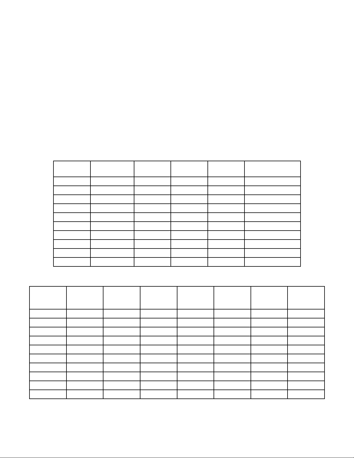
Table III-1 Full Scale Range Viscosity of LOW TORQUE CAP Viscometer
Cone
Number
01 1875 13.33N 0.83 0.17 1875/(22.7*N)
02 3750 13.33N 1.65 0.33 3750/(22.7*N)
03 7500 13.33N 3.30 0.66 7500/(22.7*N)
04 15000 3.33N 6.61 1.32 15000/(22.7*N)
05 30000 3.33N 13.22 2.64 30000/(22.7*N)
06 75000 3.33N 13.04 6.61 75000/(22.7*N)
07 3150 2N 1.39 0.28 3150/(22.7*N)
08 12500 2N 5.51 1.10 12500/(22.7*N)
09 50000 2N 22.03 4.41 50000/(22.7*N)
10 5000 5N 2.20 0.44 5000/(22.7*N)
Cone Constant
Range
Shear Rate
Constant
FSR at
100 RPM
FSR at
500 RPM
FSR at
any RPM
Table III-2 Full Scale Range Viscosity of HIGH TORQUE CAP Viscometer
Cone
Number
01 1875 13.33N 18.75 4.69 2.50 2.08 1875/(N)
02 3750 13.33N 37.50 9.38 5.00 4.17 3750/(N)
03 7500 13.33N 75.00 18.75 10.00 8.33 7500/(N)
04 15000 3.33N 150.00 37.50 20.00 16.67 15000/(N)
05 30000 3.33N 300.00 75.00 40.00 33.33 30000/(N)
06 75000 3.33N 750.00 187.50 100.00 83.33 75000/(N)
07 3150 2N 31.50 7.88 N/A N/A 3150/(N)
08 12500 2N 125.00 31.25 N/A N/A 12500/(N)
09 50000 2N 500.00 125.00 N/A N/A 50000/(N)
10 5000 5N 50.00 12.50 6.67 5.56 5000/(N)
Cone
Constant
Range
Shear
Rate
Constant
FSR
at
100 RPM
FSR
at
400 RPM
FSR
at
750 RPM
FSR
at
900 RPM
FSR
at
any RPM
(Continued)
Page 3
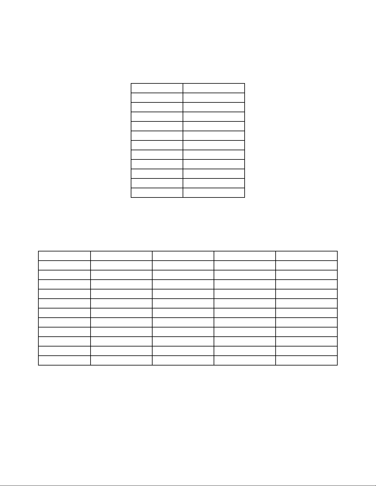
Table III-3 Accuracy for LOW TORQUE CAP Viscometer
Cone Number ≤ 500 RPM
10-100% FSR
01 ± 2%
02 ± 2%
03 ± 2%
04 ± 2%
05 ± 2%
06 ± 2%
07 ± 2%
08 ± 2%
09 ± 2%
10 ± 2%
Table III-4 Accuracy for HIGH TORQUE CAP Viscometer
Cone Number ≤ 400 RPM 750 RPM 900 RPM 900 RPM
10-100% FSR 10-100% FSR ≤ 50% FSR > 50% FSR
01 ± 2% ± 2% ± 2% ± 4%
02 ± 2% ± 2% ± 2% ± 4%
03 ± 2% ± 2% ± 2% ± 4%
04 ± 2% ± 3% ± 3% ± 6%
05 ± 2% ± 4% ± 4% ± 8%
06 ± 2% ± 5% ± 5% ± 10%
07 ± 2% N/A N/A N/A
08 ± 2% N/A N/A N/A
09 ± 2% N/A N/A N/A
10 ± 2% ± 2% ± 2% ± 2%
Page 4

TABLE OF CONTENTS
I. INTRODUCTION ..................................................................................................................... 3
I.1 Components .................................................................................................................................................... 3
I.2 Utilities
I.3 Specications ..................................................................................................................................................5
I.4 Installation ........................................................................................................................................................5
I.5 Safety Symbols and Precautions .............................................................................................................. 6
I.6 Key Functions .................................................................................................................................................. 7
I.7 Viscosity and Temperature Display ..........................................................................................................7
I.8 Cleaning ............................................................................................................................................................8
II. GETTING STARTED ................................................................................................................ 9
II.1 Power ON ..........................................................................................................................................................9
II.2 Cone Spindle Selection and Setting .......................................................................................................9
II.3 Speed Setting ................................................................................................................................................11
II.4 Temperature Control Setting ...................................................................................................................11
II.5 Hold Time Settings ......................................................................................................................................12
II.6 Run Time .........................................................................................................................................................12
II.7 Printing ............................................................................................................................................................12
II.8 Run and Stop Keys .......................................................................................................................................13
............................................................................................................................................................... 4
III. OPERATION ..........................................................................................................................14
III.1 Full Scale Range and Accuracy of Measurement ...............................................................................14
III.2 Accuracy of Viscosity and Temperature ..............................................................................................15
III.3 Calibration Verication ..............................................................................................................................17
III.4 Cone Calibration ..........................................................................................................................................20
III.5 Repeatability .................................................................................................................................................21
III.6 Making Viscosity Measurements ...........................................................................................................22
APPENDIX A - Variables in Viscosity Measurement .....................................................................................24
APPENDIX B - Warranty Repair and Service ...................................................................................................26
This manual intended for use with CAP 1000+ series viscometers which have serial numbers beginning with a prex of “CPN”.
CAP1000 and 2000 Viscometers with a serial number prex of “CP” require a different manual. Please contact Brookeld or your authorized dealer/representative to obtain this manual.
Brookeld Engineering Labs., Inc. Page 2 Manual No. M02-312A0607
Page 5

I. INTRODUCTION
The CAP 1000+ Series Viscometers are high shear rate instruments with Cone Plate geometry
and integrated temperature control of the test sample material. Rotational speeds include 750
RPM and 900 RPM. Viscosity measurement ranges depend upon the cone spindle and the rotational speed (shear rate). Viscosity is selectively displayed in units of centipoise (cP), poise
(P), milliPascal seconds (mPa•s) or Pascal seconds (Pa•s). Temperature control of sample is
possible between either 5°C (or 15°C below ambient, whichever is higher) and 75°C or 50°C
and 235°C depending on viscometer model.
The CAP 1000+ can also be ordered with a single, customized speed between 5 and 1000 rpm.
In this case, the CAP 1000+ can offer, when necessary, low shear rate capability.
The CAP 1000+ Viscometer can display either CGS or SI units:
CGS SI Comment
Viscosity: P or cP Pa•s or mPa•s 0.1 Pa•s = 1 P (= 100 cP)
Shear Rate: Sec
Speed: RPM RPM
Temperature: °C °C
The CAP 1000+ Viscometer outputs data to a parallel printer in the CGS and SI units:
CGS SI Comment
-1
Sec
-1
Viscosity: P or cP Pa•s or mPa•s 0.1 Pa•s = 1 P (= 100 cP)
Full Scale Range (F.S.R.): % %
Shear Stress: Dynes/cm2 N/m2 1.0 N•m = 107 dyne•cm
Shear Rate: Sec
-1
Sec
-1
Speed: RPM RPM
Run Time: Seconds Seconds
Temperature: °C °C
Cone Spindle Number: No. No.
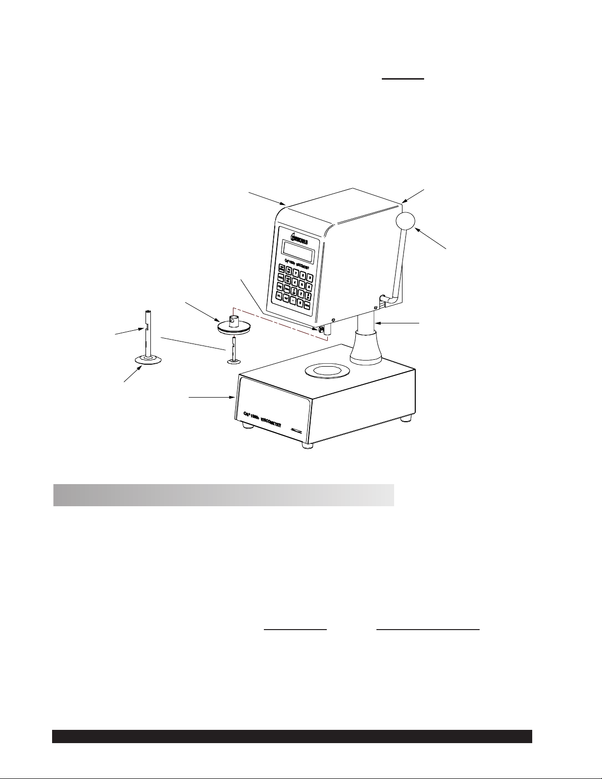
I.1 Components
The following items are included; see Figure I-1
Part No.
1. CAP 1000+ Viscometer
2. Cone Spindle(s) ........................................CAP-S-0X (X will be shown as a number 1-10)
3. Spindle Case ..........................................CAP-106Y
4. Solvent Trap ..........................................CAP-1K-63
5. Power Cord: 115V ..................................DVP-65
220V .................................DVP-66
UK.....................................DE-8
Germany ...........................DE-7
6. Operating Instructions Manual ................M/02-312
Brookeld Engineering Labs., Inc. Page 3 Manual No. M02-312A0607
Page 6
The following optional items may have been included:
Head
Serial Tag Info
on Back of
Viscometer Head
Handle for Raising
and Lowering
Viscometer Head
Thumb Screw
P/N CAP-85Y
Solvent Trap
P/N C1K-63
The Flat
Cone Spindle
P/N CAP-S-XX
Base
Console
Column
Part No.
7. Viscosity Standard Fluid for calibration See Table III-5 and III-6 in Section III.
Please check to be sure that you have received all components and that there is no damage.
If you are missing any parts, please notify Brookeld or your local dealer immediately. Any
shipping damage must be reported to the carrier. Save the packing container, if possible, for
future use when returning the viscometer to Brookeld or an authorized dealer for service.
Figure I-1: Components
I.2 Utilities
Input Voltage: 115 VAC or 230 VAC
Input Frequency: 50/60 Hz
Power Consumption: Less than 345 WATTS
Fuses: (2) 5x20mm, 3A, 250V; Fast Acting for 125VAC
(2) 5x20mm, 1.6A, 250V; Fast Acting for 250VAC
Power Cord Color Code:
United States Outside United States
Hot (live) Black Brown
Neutral White Blue
Ground (earth) Green Green/Yellow
Brookeld Engineering Labs., Inc. Page 4 Manual No. M02-312A0607
Page 7
I.3 Specications
Torque Range: Low 797-7,970 dyne•cm (designated on serial tag as 1/23 CAP)
High 18,100-181,000 dyne•cm (designated on serial tag as 1.0 CAP)
Speeds: 750 RPM and 900 RPM or
single speed from 5-900 RPM as specied at time of order
Temperatures: CAP 1000+L 5°C (or 15°C below ambient, whichever is higher) to
75°C
CAP 1000+H 50°C to 235°C
All models provide 0.1°C increments
Weight: Gross Weight 36 lb 16.3 kg
Net Weight 27 lb 12.3 kg
Carton Volume 4.9 cu ft 0.15 m
3
Carton Dimensions 18 in. L x 18 in. W x 26 in. H
48 cm. L x 48 cm. W x 66 cm. H
Materials: CAP cone spindles and temperature plates are made of tungsten carbide.
Operating CAP 1000+ Viscometers must be operated within the following
Environment: ambient temperatures: +5°C (41°F) to 40°C (104°F)
and humidity: 20% to 80% R.H. (non-condensing atmosphere)
I.4 Installation
Note: DO NOT lift the viscometer by the handle or head! LIFT only by the base console or
column!
1) Set the viscometer on a clean level bench surface.
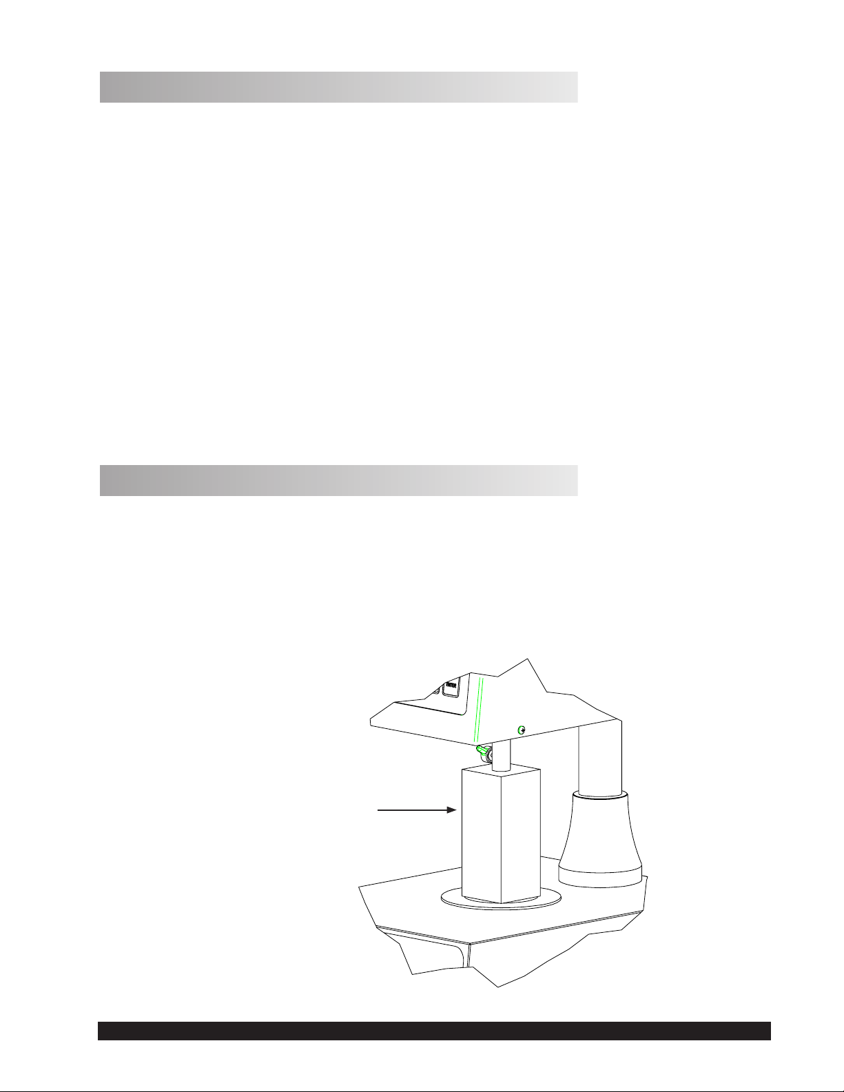
2) Remove shipping foam insert from the plate area on the CAP Viscometer. Store the
foam insert for future use when shipping or transporting CAP Viscometer.
Foam Insert Used
When Sh i p pi ng
CAP Viscometer
Figure I-2: Detail of Foam Insert
Brookeld Engineering Labs., Inc. Page 5 Manual No. M02-312A0607
Page 8

3) Verify that the viscometer’s power requirements match your power source BEFORE connecting it to power.
The AC input voltage and frequency must be within the appropriate range as shown on
the back of the viscometer head .
Note: The CAP Viscometer must be earth grounded. Use the three (3) wire power cord! Do
not alter!
4) Connect the power cord to the viscometer and to the power supply (source).
5) If using a printer, connect the printer cable to the printer port and printer.
Note: Ensure that both the printer and the CAP 1000+ are off when connecting cables.
I.5 Safety Symbols and Precautions
Safety Symbols
The following explains safety symbols which may be found in this operating manual.
Indicates hazardous voltages may be present.
Caution: HOT surface.
Refer to the manual for specic warning or caution information to avoid personal injury
or damage to the instrument.
Safety Overview
If this instrument is used in a manner not specied by the manufacturer, the protection
provided by the instrument may be impaired.
This instrument is not intended for use in a potentially hazardous environment.
In case of emergency, turn off the instrument and then disconnect the electrical cord
from the wall outlet.
Brookeld Engineering Labs., Inc. Page 6 Manual No. M02-312A0607
Page 9
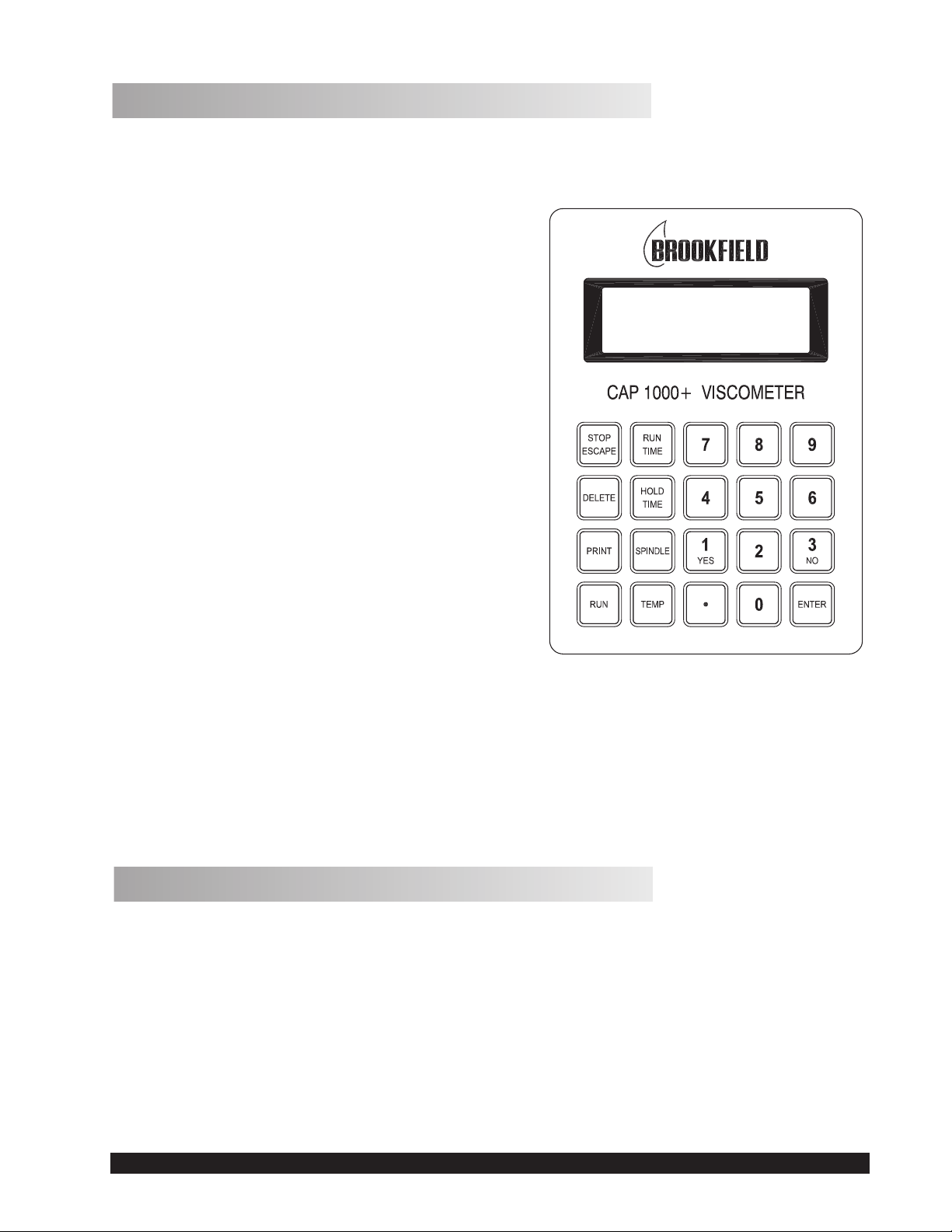
I.6 Key Functions
Figure I-3 shows the control keys on the face of the viscometer display panel:
NUMERIC 0 - 9
These keys are used for data entry
ENTER
This key accepts entered data.
STOP / ESCAPE
Stops cone spindle rotation at any time. Exits data
entry eld.
DELETE
This key clears entered values for input selec-
tions.
PRINT
This key sends data to the parallel printer, when
connected.
RUN
This key starts spindle rotation.
RUN TIME
This key selects time entry mode (time of spindle
rotation).
HOLD TIME
This key selects time entry mode (wait time be-
fore spindle rotates).
SPINDLE
This key selects the cone spindle entry mode.
TEMP
This key selects the temperature entry mode.
I.7 Viscosity and Temperature Display
Viscosity is displayed in either P=Poise or cP=Centipoise (CGS system) or Pa•s=Pascal seconds or
mPa•s=milliPascal seconds (SI system). If the viscosity measurement is over range,
“EEEE” will be displayed. Brookeld recommends a minimum torque reading of 10% when
making viscosity measurements. If the torque value is between 0 and 10%, the display will
ash to indicate an under range condition. If the viscometer nal reading is below zero, negative values will be displayed.
Figure I-3
Temperature is displayed in °C=degrees centigrade.
Brookeld Engineering Labs., Inc. Page 7 Manual No. M02-312A0607
Page 10

I.8 Cleaning
Instrument, Keypad & Painted Surfaces:
Clean with dry, non-abrasive cloth. Do not use solvents or cleaners.
Immersed Components (spindles/cones) and temperature controlled plate:
All immersed components are made of carbide steel. Clean with non-abrasive cloth
and solvent appropriate for sample material that is not aggressive to immersed components.
Do not use metal objects to clean the plate surface, as scratching of the plate may oc-
cur and compromise cone calibrations.
Note: When cleaning, take care not to apply excessive force which may bend the spindle shaft
or otherwise damage the instrument.
Brookeld Engineering Labs., Inc. Page 8 Manual No. M02-312A0607
Page 11

II. GETTING STARTED
II.1 Power ON
Turn the power ON using the switch located on the rear of the base console.
The display will sequentially show BROOKFIELD, then the model of the viscometer and the
version number. After about four seconds, the main screen will be displayed (Figure II-1).
MAIN SCREEN
0.00P 0.0%
Run15 Spindle04
50.0C 900RPM
Figure II-1
The instrument will be set to the default temperature.
CAP L Series Viscometer 25.0°C
CAP H Series Viscometer 50.0°C
Special Functions
Units of measure and speed of rotation may be selected through the
This screen is accessed by pressing the STOP key during instrument power up.
The CAP 1000+ can be congured to operate at 750 RPM or 900 RPM. This selection is set
by choosing 1=SPEED in the
special functions screen, then selecting 1=750 RPM or 2=900
RPM and pressing ENTER.
The CAP 1000+ can be congured to display viscosity in one of four units:
tipoise (cP), Pascal Seconds (Pa•s) or milliPascal seconds (mPa•s). This selection is set by
choosing 2=U in the
then pressing
ENTER.
special functions screen, selecting 1=P, 2=cP, 3=Pa•s, or 4=mPa•s, and
Once the CAP 1000+ has been congured, the instrument must be turned OFF. The congura-
tion will be stored in memory.
II.2 Cone Spindle Selection and Setting
Raise the viscometer handle to its highest position.
The CAP cones have viscosity ranges as shown in Appendix A. After selecting the appropriate cone for the viscosity range to be utilized, carefully attach the cone to the viscometer as
shown in Figure II-2.
special functions screen.
Poise (P), Cen-
Be sure to insert the spindle completely into the adapter sleeve; align the at (see Figure I-1)
on the spindle with the thumb screw and then tighten.
Brookeld Engineering Labs., Inc. Page 9 Manual No. M02-312A0607
Page 12

When using the solvent trap (Figure II-2), connect it to the cone adapter by sliding it up,
Thumb Screw
Solvent Trap
Cone Spindle
passing the slot by the thumb screw and turning the trap clockwise onto the thumbscrew.
Slide the cone up into the adapter as far as it will go and hand lock it in place with the thumb
screw. Tighten the thumb screw rmly and securely.
Figure II-2: Cone Attachment
Press the SPINDLE key. The display will change to the spindle entry screen. Using the number
keys, type in the required spindle number.
Two digits must be entered for the cone number. For cone 01 through 09, the rst number
remains as “0”.
The default cone setting on power-up will be the last cone entry prior to shutting off the
Note:
viscometer.
After the correct two (2) digits have been entered, press the ENTER key and the cone will be
accepted for viscometer calculations. The screen will display the following message:
Spindle04
CALIBRATE? YES/NO
Figure II-3
If you are using the CAP Viscometer for the rst time or have just received the instrument back
from being serviced, press YES and see Section III. Cones supplied at the time of order are
calibrated to the viscometer by Brookeld prior to shipment, but should still be veried with a
calibration check prior to use for the rst time. Cones purchased separately at a later time by
the user must also be calibrated prior to making viscosity measurements.
Otherwise, there is no requirement to perform a cone calibration.
Brookeld Engineering Labs., Inc. Page 10 Manual No. M02-312A0607
Page 13

Note: 1. CAP Viscometers allow for only one cone at a time of the same cone number to
be calibrated to the viscometer. Multiple cones of the same cone number must each
be calibrated to the viscometer before operation (refer to Appendix B).
2. A special feature of the CAP series viscometers allows the user to perform a cone
calibration with viscosity standard uids.
3. Cones entered as 11 through 99 must be rst calibrated following the directions in
Section III.
If you are not going to calibrate the cone, continue by pressing the NO key, then the ENTER
key. The viscometer will display the MAIN SCREEN (Figure II-1).
If you are going to calibrate the cone, press the
calibration instructions under
II.3 Speed Setting
The CAP 1000+ is a single speed viscometer. It is supplied from the factory in two congurations: standard and custom. The speed of rotation is shown in the lower right corner of the
display.
Standard
The CAP 1000+ Viscometer is supplied with two speeds: 750 RPM and 900 RPM. All CAP
1000+ Viscometers are factory-set at 900 RPM. To change the setting, press and hold the
key during the power up sequence. Choose “1=SPEED (RPM)” from the special functions
screen and select the required speed. This selection will become the default speed.
Custom
The CAP 1000+ Viscometer is congured to operate at one speed as specied at the time of
order. This speed is indicated on the instrument serial tag.
To begin spindle rotation, press the RUN key.
II.4 Temperature Control Setting
YES key, refer to Section III, and follow the
Cone Calibration.
STOP
Press the TEMP key and the current temperature setting will blink. The default temperature on
start-up is 25.0°C on low temperature models
and 50.0°C on high temperature models.
The temperature ranges are:
Low temperature: 5°C (or 15°C below ambient, whichever is higher) to 75°C
High temperature: 50°C to 235°C
Use the number keys to type in the required set point. The temperature can be set in increments
of 0.1°C. You can turn off the heater by entering 0 on the high temperature unit only.
Use the
Note:
ENTER key to accept the new set point.
Thermal equilibrium of the sample and of the spindle must be considered for best
measurement results. Upon powering up the Viscometer or after changing the tem-
perature set point, allow sufcient time for the plate to reach the desired temperature.
Brookeld Engineering Labs., Inc. Page 11 Manual No. M02-312A0607
Page 14

It is recommended to have the spindle in contact with the plate prior to introducing the
sample material to ensure that the spindle is also at the temperature of test. Brookeld
recommends using the solvent trap at all times to enhance the temperature control of the
sample material. After inserting the sample material onto the plate, lower the spindle
and solvent trap and allow sufcient time for thermal equilibrium prior to starting the
test.
Temperature control on the high temperature unit can be restored by entering a setpoint between
50°C and 235°C.
II.5 Hold Time Settings
Hold time sets the time period between when the RUN key is pressed and when the spindle
begins to rotate. This time period is normally used to ensure thermal equilibrium of the sample
and spindle. The hold time range is 0 to 999 seconds.
Press the HOLD TIME key and the current hold time will blink on the default screen. Use the
number keys to type in the required hold time and press the ENTER key.
Note: When the hold time is set to zero, it is not displayed on the default screen.
II.6 Run Time
Run time sets the time period of spindle rotation. The run time range is 0 to 999 second.
Press the RUN TIME key and the current run time will blink on the default screen. Use the
number keys to type in the required run time and press the ENTER key.
Note: Run time will be shown on the default screen only when hold time is set to zero.
A run time of zero sets the viscometer to innite run mode. In this mode, the spindle will rotate
at the set speed for as long as the RUN button is pressed. When the RUN key is released, the
spindle will stop rotating.
Note:
II.7 Printing
Pressing the PRINT key at any time sends information on test parameters to the printer port.
However, viscosity, full scale range and shear stress data will only be printed after it is rst
displayed during a test run.
To print a heading, press and hold the
test by pressing the RUN key. Press the
With a run time of zero, the hold time will not be used.
STOP/ESCAPE key and press the PRINT key. Then start the
PRINT key whenever data is desired during the test.
Example of CAP 1000+ PRINT OUTPUT showing heading and data.
VISCOSITY
(POISE)
- - 25.0 - 10000 0750 20 02
Brookeld Engineering Labs., Inc. Page 12 Manual No. M02-312A0607
F.S.R.
(%)
TEMP
(Deg C)
S.STRESS
(D/CM2)
Figure II-4
S.RATE
(1/sec)
SPEED
(RPM)
TIMER
(SEC)
CONE
No.
Page 15

A maximum of 999 seconds can be printed when running in manual TIMER mode (00). Over
999 seconds will print EEE.
The TIMER (SEC) column will indicate the accumulated time of running at the moment the
print key is pressed while the cone is rotating. This time value will not include the hold time.
At the end of a test, data will automatically be sent to the printer port.
II.8 Run and Stop Keys
The RUN key has three functions:
1. Press RUN to begin a test.
2. Press and hold the RUN key for continuous rotation when 00 is the timer setting.
3. Used in executing a cone calibration.
The STOP key has three functions:
1. Stops the cone rotation at any time.
2. Pressing and holding the STOP/ESCAPE key during power up selects the special func-
tions mode where the viscosity display units and speed of rotation may be changed.
(Section II.1)
3. Pressing and holding the STOP and PRINT keys simultaneously executes the printing of
a new heading (Section II.7).
Brookeld Engineering Labs., Inc. Page 13 Manual No. M02-312A0607
Page 16

III. OPERATION
The CAP 1000+ Viscometer is delivered from the factory with two available speeds for operation at 750 rpm or 900 rpm. Information on how to access these speeds is detailed in section
II.3 “Speed Setting”. Your viscometer may operate at a different rotational speed based on what
was specied at the time of order. To determine what speed your viscometer has been set to,
power on the viscometer and note the operating speed on the main screen display.
III.1 Full Scale Range and Accuracy of Measurement
Full Scale Range (FSR) viscosity is the maximum viscosity that can be measured and occurs
when the % torque is 100. Brookeld recommends that viscosity measurements be made between 10 and 100% torque.
There are two tables to consult for viscosity range information, depending on which torque
model viscometer you purchased. To determine which torque model you have, consult the se-
rial tag of your viscometer or the certicate of calibration that accompanied the instrument or
the display on power up.
23CAP 1000+ = Low Torque CAP 1000+ = High Torque
Full Scale Range (FSR) is based on the cone spindle your are using, the torque model of your
viscometer, and the speed of spindle rotation. The tables below provide information on FSR
by torque model for the most common factory set speeds:
Table III-1: Full Scale Range Viscosity for Low Torque CAP 1000+
Cone
Number
01 1875 13.33N 0.83 0.11 .0597 1875/(22.7*N)
02 3750 13.33N 1.65 0.22 .165 3750/(22.7*N)
03 7500 13.33N 3.30 0.44 .330 7500/(22.7*N)
04
05 30000 3.33N 13.22 1.76 1.47 30000/(22.*N)
06 75000 3.33N 33.04 4.41 3.67 75000/(22.7*N)
07 3150 2N 1.39 * * 3150/(22.7*N)
08 12500 2N 5.51 * * 12500/(22.7*N)
09 50000 2N 22.3 * * 50000/(22.7*N)
10 5000 5N 2.20 0.29 2.20 5000/(22.7*N)
Cone
Range
Constant
15000 3.33N
Shear Rate
Constant
FSR Poise
at 100
RPM
6.61
FSR
Poise at
750 RPM
FSR Poise
at 900
RPM
0.88 0.73 15000/(22.7*N)
FSR Poise at any
RPM
N= RPM
Poise x 100 = centiPoise
*use of this cone at these RPM is not recommended
Brookeld Engineering Labs., Inc. Page 14 Manual No. M02-312A0607
Page 17

Table III-2: Full Scale Range Viscosity for High Torque CAP 1000+
Cone
Number
01 1875 13.33N 18.75 2.50 2.08 1875/N
02 3750 13.33N 37.50 5.00 4.17 3750/N
03 7500 13.33N 75.00 10.00 8.33 7500/N
04
05 30000 3.33N 300.00 40.00 33.33 30000/N
06 75000 3.33N 750.00 100.00 83.33 75000/N
07 3150 2N * * * 3150/N
08 12500 2N * * * 12500/N
09 50000 2N * * * 50000/N
10 5000 5N 50.00 6.67 5.56 5000/N
Cone
Range
Constant
15000 3.33N
Shear Rate
Constant
FSR Poise
at 100
RPM
150.00
FSR
Poise at
750 RPM
20.00 16.67 1500/N
FSR Poise
at 900
RPM
Poise at any RPM
N= RPM
Poise x 100 = centiPoise
*use of this cone at these RPM is not recommended
You can also determine FSR for a speed setting that was selected at the time of order that is not
in the above tables by doing a simple calculation:
• For Low Torque CAP instruments:
Cone range constant / (22.7 * N) = FSR (Poise) where N = RPM
• For High Torque CAP instruments:
Cone range constant / N = FSR (Poise) where N = RPM
The last column in the above tables shows this calculation.
III.2 Accuracy of Viscosity and Temperature
The following tables indicate the accuracy of the viscosity measurement for the CAP 1000+
Viscometer using CAP spindles 01-10. This accuracy depends on both the rotational speed of the
cone and the percent of Full Scale Range (%FSR) in Poise at which the viscosity is measured.
Accuracy is stated in Poise (P) and is calculated as a % of the FSR viscosity.
To calculate accuracy:
• Determine FSR viscosity in Poise for the torque model, cone spindle, and speed of rotation,
using the information in Tables III-1 or III-2.
• Find the column that best denes the speed of rotation used for the measurement and your
reported % FSR from the measurement.
• Consult the table below to determine the accuracy of your measurement
• Multiply the accuracy by the FSR viscosity if you need your accuracy stated in Poise.
Brookeld Engineering Labs., Inc. Page 15 Manual No. M02-312A0607
Page 18

Table III-3: Accuracy for Low Torque CAP 1000+
Cone ≤400 RPM 750 RPM 900 RPM 900 RPM
10-100% FSR 10-100% FSR ≤50% FSR >50% FSR
01 ±2.0% ±2.0% ±2.0% ±2.0%
02 ±2.0% ±2.0% ±2.0% ±2.0%
03
04 ±2.0% ±2.0% ±2.0% ±2.0%
05 ±2.0% ±2.0% ±2.0% ±2.0%
06 ±2.0% ±2.0% ±2.0% ±2.0%
07 ±2.0% * * *
08 ±2.0% ±2.0% ±2.0% ±2.0%
09 ±2.0% ±2.0% ±2.0% ±2.0%
10 ±2.0% ±2.0% ±2.0% ±2.0%
* Not recommended for use at these RPM
Cone ≤400 RPM 750 RPM 900 RPM 900 RPM
01 ±2.0% ±2.0% ±2.0% ±4.0%
02 ±2.0% ±2.0% ±2.0% ±4.0%
03
04 ±2.0% ±3.0% ±3.0% ±6.0%
05 ±2.0% ±4.0% ±4.0% ±8.0%
06 ±2.0% ±5.0% ±5.0% ±10.0%
07 ±2.0% * * *
08 ±2.0% * * *
09 ±2.0% * * *
10 ±2.0% ±2.0% ±2.0% ±2.0%
* Not recommended for use at these RPM
±2.0% ±2.0%
Table III-4: Accuracy for High Torque CAP 1000+
10-100% FSR 10-100% FSR ≤50% FSR >50% FSR
±2.0% ±2.0%
±2.0%
±2.0%
±2.0%
±4.0%
The specication of temperature accuracy on CAP Viscometers is stated below:
LOW TEMP UNITS:
• In ambient conditions of 15°C to 30°C, accuracy is +/- 0.5°C when the temperature set point
on the viscometer is 5°C to 75°C.
• In ambient conditions outside of 15°C to 30°C, accuracy is +/- 1.0°C when the temperature
set point on the viscometer is 5°C to 75°C.
HIGH TEMP UNITS:
• In ambient conditions of 15°C to 30°C, accuracy is +/- 0.5°C when the temperature set point
on the viscometer is 50°C to ≤100°C.
• In ambient conditions of 15°C to 30°C, accuracy is +/- 1.0°C when the temperature set point
on the viscometer is 101°C to 235°C.
Brookeld Engineering Labs., Inc. Page 16 Manual No. M02-312A0607
Page 19

• In ambient conditions outside of 15°C to 30°C, accuracy is +/- 2.0°C when the temperature
set point on the viscometer is 50°C to ≤100°C.
III.3 Calibration Verication
Accuracy of the CAP 1000+ Viscometer can be veried by performing a calibration verication.
The cones/spindles that were shipped with the viscometer were calibrated to the viscometer by
Brookeld prior to shipment. If your viscometer was returned to Brookeld or an authorized
Brookeld Dealer, then any cones/spindles that were returned for service will have been cali-
brated to the viscometer prior to shipment.
When you receive the instrument, perform a calibration verication on each cone spindle to
ensure that each spindle is measuring correctly. This will ensure that everything is in good
working order and that the instrument and/or cone spindles have not experienced a change
during shipment. If the calibration verication fails then you can take advantage of the CAP
Viscometer’s unique feature which allows the operator to recalibrate each cone spindle to the
CAP Viscometer (See Section III.4).
Calibration verication is also performed when viscosity readings with your product are suspect. Verifying the calibration will determine if the cone needs to be recalibrated to the instrument. This will help you to determine if the discrepant readings on your product are due to
cone/instrument performance, or your method or your product. Complete cone recalibration
is discussed in Section III.4.
To perform a cone calibration verication, you will need a mineral oil from Table III-5 or Table
III-6. Determine what range model CAP 1000+ Viscometer you have (Low Torque or High
Torque), which temperature range (L = Low, H = High; consult the instrument serial tag) and
what cone your are using.
You must use the following method, regardless of what your test calls for:
1. Put the cone in the down position, and make sure that the solvent trap is covering the
spindle.
2. Allow the viscometer to stabilize for at least 30 minutes at 25°C (Low Temp units) or at
60°C (High Temp) if the temperature that you normally operate is different; otherwise, wait
5 minutes, then make sure the cone is in the down position and that the solvent trap is on.
3. At the end of the temp stabilization period, dispense the appropriate volume of uid (consult
Table III-5 or Table III-6). Figure III-1 shows how to dispense the uid onto the plate and
determine visually if the amount is appropriate.
Brookeld Engineering Labs., Inc. Page 17 Manual No. M02-312A0607
Page 20

Figure III-1a Figure III-1b
Figure III-1c Figure III-1d
4. Run a viscosity test and record the viscosity value when the reading has stabilized.4. Run
a viscosity test and record the viscosity value when the reading has stabilized.
5. Compare the recorded viscosity to the actual value of the standard and verify that it falls
within the accuracy limits stated in Tables III-3 and III-4.
6. If the test fails, repeat again to make sure that every step was performed correctly. If the
test fails again, perform a cone calibration according to the procedure in Section III.4.
Brookeld Engineering Labs., Inc. Page 18 Manual No. M02-312A0607
Page 21

Table III-5: Viscosity Standard Fluids for Calibration of CAP Spindles on Low Torque CAP 1000+
LOW
TORQUE
Cone
LOW
TEMP
Fluid
Part
Num-
ber
Nomi-
nal
Value
(cP)
Temp
(°C)
Sample
Size
(micro
liters)
LOW
TORQUE
Cone
HIGH
TEMP
Fluid
Part
Num-
ber
Nomi-
nal
Value
(cP)
Temp
(°C)
Sam-
ple
Size
(micro
liters)
CAP-S-01 CAP0L 57 25 67 CAP-S-01 CAP0H 57 60 67
CAP-S-02 CAP1L 89 25 38 CAP-S-02 CAP1H 89 60 38
CAP-S-03 CAP2L 177 25 24 CAP-S-03 CAP2H 177 60 24
CAP-S-04 CAP3L 354 25 124 CAP-S-04 CAP3H 354 60 124
CAP-S-05 CAP4L 708 25 67 CAP-S-05 CAP4H 708 60 67
CAP-S-06 CAP5L 1417 25 32 CAP-S-06 CAP5H 1417 60 32
CAP-S-07 CAP1L 89 25 1700 CAP-S-07 CAP1H 89 60 1700
CAP-S-08 CAP3L 354 25 400 CAP-S-08 CAP3H 354 60 400
CAP-S-09 CAP5L 1417 25 100 CAP-S-09 CAP5H 1417 60 100
CAP-S-10 CAP2L 177 25 170 CAP-S-10 CAP2H 177 60 170
Table III-6: Viscosity Standard Fluids for Calibration of CAP Spindles on High Torque CAP 1000+
HIGH
TORQUE
Cone
LOW
TEMP
Fluid
Part
Num-
ber
Nomi-
nal
Value
(cP)
Temp
(°C)
Sample
Size
(micro
liters)
HIGH
TORQUE
Cone
HIGH
TEMP
Fluid
Part
Num-
ber
Nomi-
nal
Value
(cP)
Temp
(°C)
Sam-
ple
Size
(micro
liters)
CAP-S-01 CAP1L 89 25 67 CAP-S-01 CAP1H 89 60 67
CAP-S-02 CAP2L 177 25 38 CAP-S-02 CAP2H 177 60 38
CAP-S-03 CAP3L 354 25 24 CAP-S-03 CAP3H 354 60 24
CAP-S-04 CAP4L 708 25 124 CAP-S-04 CAP4H 708 60 124
CAP-S-05 CAP5L 1417 25 67 CAP-S-05 CAP5H 1417 60 67
CAP-S-06 CAP6L 3542 25 32 CAP-S-06 CAP6H 3542 60 32
CAP-S-07 CAP7L 1328 25 1700 CAP-S-07 CAP7H 1328 60 1700
CAP-S-08 CAP8L 5313 25 400 CAP-S-08 CAP8H 5313 60 400
CAP-S-09 CAP9L 21250 25 100 CAP-S-09 CAP9H 21250 60 100
CAP-S-10 CAP10L 236 25 170 CAP-S-10 CAP10H 236 60 170
Brookeld Engineering Labs., Inc. Page 19 Manual No. M02-312A0607
Page 22

III.4 Cone Calibration
A special feature of the CAP Series Viscometers allows the user to perform a cone calibration
using Viscosity Standard Fluids. This eld calibration will accommodate any wear on the tip
of the cone which may result from contact with the plate.
A cone calibration should be performed when: 1) using a new cone for the rst time,
Note:
2) switching between two cones of the same number and 3) verication of calibration
provides data outside of the acceptable range.
Refer to Tables III-5 and III-6 to choose the calibration uid for the spindle being calibrated.
1. Turn on the CAP 1000+ Viscometer.
2. Attach solvent trap to coupling shaft.
3. Attach spindle.
4. Place appropriate amount of sample onto the center of the Viscometer plate directly below
the spindle.
5. Pull down the handle, locking it into the lowest position, placing the spindle in contact with
the plate.
6. Lower the solvent trap.
Note: The solvent trap must be utilized when calibrating to ensure proper temperature con-
trol.
7. Select the spindle to be calibrated by using the SPINDLE key.
8. Select YES for CALIBRATE and press ENTER.
9. Enter the appropriate values for temperature (°C) and viscosity (cP) prompted by the
screen.
Viscosity values are always entered in units of CENTIPOISE (cP) no matter what units
Note:
have been selected as unit of measure for normal operation.
100 cP = 1P; 1cP = 1mPa•s; 1000 cP = 1Pa•s
Note: The Viscometer temperature control must be identical to the specied temperature for
the viscosity standard when executing the calibration. Normally calibration will be at
25°C for “L” Series CAP Viscometers and 60°C for “H” Series CAP Viscometers.
10. Allow at least 30 minutes for thermal equilibrium of the plate, calibration uid and spindle,
from instrument cold start.
11. Press the RUN key to start the calibration.
Brookeld Engineering Labs., Inc. Page 20 Manual No. M02-312A0607
Page 23

Note: The calibration process may be cancelled at any time prior to pressing RUN by
pressing the ESCAPE key.
When calibration is complete, spindle rotation will stop and the “CALIBRATION COMPLETE”
screen is displayed. (See Figure III-2). Press ENTER to continue.
CALIBRATIONCOMPLETE
PRESSENTERTOCONTINUE
If the viscometer is connected to a printer, the printout (Figure III-3) will automatically be generated. There will be values for the listed variables. The operator can enter the information by
hand on the botom of the printout.
CONE (00) CALIBRATION
VISCOSITY
(POISE)
Oper
Date: ____________________________________________________
Model/Serial #: ____________________________________________
Fluid: ____________________________________________________
FSR
(%)
TEMP
(Deg C)
ator: ________________________________________________
S.STRESS
D/CM2)
S.RATE
(1/sec)
Figure III-3
SPEED
(RPM)
III.5 Repeatability
The CAP 1000+ Viscometer is repeatable to ±0.5% of the full scale viscosity range (FSR). Due
to shear heating considerations which occur in high shear rate instrumentation, the measurement
of NIST Viscosity Standard Fluids at rotational speeds above 900 RPM will show a decrease
in viscosity with an increase in rotational speed (shear rate).
Normal forces due to the shearing of a viscoelastic uid (such as paint) are accounted for in
the CAP Series Viscometers by weight on the spindle column of 3.4 Newtons (340,000 Dynes)
total force. This is done to avoid having the cone lift off the plate, thereby changing the cone
plate geometry and producing incorrect viscosity readings. For normal forces greater than
3.4 Newtons (340,000 Dynes) total force, additional externally mounted weights are required.
However, more weight means more wear on the cone and plate. Additional weights should
only be considered when denitely required and removed when not required.
TIMER
(SEC)
CONE
No.
SAMPLE
No.
Contact Brookeld Engineering Laboratories or your Brookeld Dealer/Distributor/Representative for details on the above information.
Brookeld Engineering Labs., Inc. Page 21 Manual No. M02-312A0607
Page 24

III.6 Making Viscosity Measurements
The following procedure is recommended for making a viscosity measurement.
With the viscometer on a clean, level surface, connect it to the proper power supply (Section
I.4).
1. Turn the power switch ON (Section II.1).
The procedure assumes that the following have been done:
a) If the viscometer has been “off” for an extended period (i.e., overnight) a “warm up”
period of 30 minutes is suggested. You may choose to warm up at the temperature of
test. If a cone calibration is to be done immediately after the warm up period, temperature should be set to 60°C (calibration temperature for high temperature instruments)
or 25°C for low temperature instruments to save some time.
b) The cone calibration procedure should have been done for all cones which are used
with the instrument. Cone calibration is only required when a new cone (i.e., replacement for lost/damaged cone) is used, or when calibration check fails.
c) When making measurements with low temperature instruments (CAP 1000+L), the
solvent trap may not be required (for the containment of solvents and/or prevention of
sample “drying”). The trap should be used for all measurements with high temperature instruments (CAP 1000+H).
d) If a printer is to be used, it should be connected (AC power & viscometer to printer
cable). The CAP 1000+ will print automatically when a reading is taken if the printer
is connected and “on line.”
2. Select and attach the cone (Section II.2).
Notes: a. Lock the cone tightly into the adapter.
b. When measuring volatile samples such as paints and coatings, and when
using either a high temperature CAP 1000+H or CAP 2000+H, the solvent
trap must be put in place over the cone to prevent the test sample from
drying out during the rotation of the cone.
3. Set the temperature control (Section II.5).
4. Set the cone number.
5. Lower the handle placing the cone onto the plate. Lock the handle into its lowest position.
Drop the solvent trap over the cone.
Note: Allow ten (10) minutes for the cone to come to equilibrium temperature with the
plate.
6. Secure trap on shaft. Solvent trap may be hot, spindle & plate too. Raise the handle.
Place the sample to be measured onto the plate below the cone and solvent trap. Don’t use
plastic spatulas/syringes if the plate temperature is above 50°C. Refer to
Table III-5 or
III-6 for recommended sample sizes. Lower the cone and solvent trap.
Brookeld Engineering Labs., Inc. Page 22 Manual No. M02-312A0607
Page 25

Notes: a. Lower the handle gently. DO NOT FORCE THE CONE ONTO THE
PLATE.
b. The sample must completely cover the face of the cone and extend beyond the
edge of the cone about 1.0 mm.
c. Release the solvent trap placing it onto the plate over the cone so it does not
touch the cone shaft.
The user should ensure that the substances placed under test do not release poisonous,
toxic or ammable gases at the temperatures to which they are subjected to during the
testing.
7. Allow the cone, plate and sample to equilibrate to the temperature control setting.
Note: A minimum of one (1) to three (3) minutes equilibrium time is recommended, de-
pending upon the sample.
8. Set the Run Time for rotating the cone (Section II.6) and the Hold Time.
9. Put the printer on-line (optional, Section II.7).
10. Press the RUN key and execute the viscosity measurement.
Note: Due to the dynamics of shearing a uid in the CAP “H” series Viscometers, the
temperature display may indicate a deection from the equilibrium temperature
setting as the cone begins rotating at high shear rates. The temperature display may
indicate the temperature of the plate and the momentary changes show the cycling
of the temperature control at high temperature. The precision of the viscosity mea-
surement is maintained within the limits specied in Table 3.1.
11. Read the results of the sample test on the printer or write down the test conditions and vis-
cosity results from the viscometer display.
12. Relocate the solvent trap onto the cone adapter and raise the handle.
Caution: HOT surface.
13. It is recommended to remove the cone for cleaning. However, with care, the cone can be
cleaned in place.
Caution: HOT surface.
14. Clean the viscometer plate (refer to Section I.8).
Caution: HOT surface.
Brookeld Engineering Labs., Inc. Page 23 Manual No. M02-312A0607
Page 26

APPENDIX A - Variables in Viscosity Measurements
As with any instrument measurement, there are variables that can affect a Viscometer measure-
ment. These variables may be related to the instrument (Viscometer), or the test uid. Variables
related to the test uid deal with the rheological properties of the uid, while instrument variables
would include the Viscometer design and the spindle geometry system utilized.
Rheological Properties
Fluids have different rheological characteristics that can be described by Viscometer measure-
ments. We can then work with these uids to suit our lab or process conditions.
There are two categories of uids:
Newtonian - These uids have the same viscosity at different Shear Rates (different
RPMs) and are called Newtonian over the Shear Rate range they are
measured.
Non-Newtonian - These uids have different viscosities at different shear rates (different
RPMs). They fall into two groups:
1) Time Independent non-Newtonian
2) Time Dependent non-Newtonian
The time dependency is the time they are held at a given Shear Rate (RPM). They are nonNewtonian, and when you change the Viscometer spindle speed, you get a different viscosity.
Time Independent
Pseudoplastic - A pseudoplastic material displays a decrease in viscosity with an increase
in shear rate, and is also known as “shear thinning”. If you take Viscometer readings from a low to a high RPM and then back to the low RPM,
and the readings fall upon themselves, the material is time independent
pseudoplastic and shear thinning.
Time Dependent
Thixotropic - A thixotropic material has decreasing viscosity under constant shear
rate. If you set a Viscometer at a constant speed, recording P values
over time, and nd that the P values decrease with time, the material is
thixotropic.
Brookeld publication,
“More Solutions to Sticky Problems” includes a more detailed discus-
sion of rheological properties and non-Newtonian behavior.
Brookeld Engineering Labs., Inc. Page 24 Manual No. M02-312A0607
Page 27

Viscometer Related Variables
• Most uid viscosities are found to be non-Newtonian. They are dependent on Shear Rate and
the spindle geometry conditions. The specications of the Viscometer cone and plate geom-
etry will affect the viscosity readings. For example, if one reading is taken at 750 rpm, and a
second at 900 rpm, the two viscosity values produced may be different because the readings
were made at different shear rates. The faster the spindle speed, the higher the shear rate.
• The shear rate of a given measurement is determined by the rotational speed and the cone
angle.
• A repeatable viscosity test should control or specify the following:
1. Viscometer model
2. Cone used
3. Test temperature
4. Test speed [or the shear rate]
5. Length of time to record viscosity
6. Sample volume sufcient to cover the face of the cone
APPENDIX B - Warranty Repair and Service
Brookeld Engineering Labs., Inc. Page 25 Manual No. M02-312A0607
Page 28

APPENDIX B - Warranty Repair and Service
Warranty
Brookeld Viscometers are guaranteed for one year from date of purchase against defects in
materials and workmanship. They are certied against primary viscosity standards traceable to
the National Institute of Standards and Technology (NIST). The Viscometer must be returned
to Brookeld Engineering Laboratories, Inc. or the Brookeld dealer from whom it was pur-
chased for warranty service. Transportation is at the purchaser’s expense. Remove the spindle
from the viscometer and attach the shipping cap to the pivot cup to prevent shipping damage.
The Viscometer should be shipped in its carrying case together with all spindles originally
provided with the instrument.
For repair or service in the
United States return to:
Brookeld Engineering Laboratories, Inc.
11 Commerce Boulevard
Middleboro, MA 02346 U.S.A.
Telephone: (508) 946-6200 FAX: (508) 923-5009
www.brookeldengineering.com
For repair or service outside the United States consult Brookeld Engineering Laboratories, Inc. or the
dealer from whom you purchased the instrument.
For repair or service in the United Kingdom return to:
Brookeld Viscometers Limited
1 Whitehall Estate
Flex Meadow, Pinnacles West
Harlow, Essex CM19 5TJ, United Kingdom
Telephone: (44) 27/945 1774 FAX: (44) 27/945 1775
www.brookeld.co.uk
For repair or service in Germany
return to:
Brookeld Engineering Laboratories Vertriebs GmbH
Hauptstrasse 18
D-73547 Lorch, Germany
Telephone: (49) 7172/927100 FAX: (49) 7172/927105
www.brookeld-gmbh.de
For repair or service in China return to:
Guangzhou Brookeld Viscometers and Texture Instruments Service Company Ltd.
Room C1, 5/F, Tianxing Building East Tower, No. 21, Zhongshan Yi Road, Yuexiu District
Guangzhou, 510600, P. R. China
Telephone: (86) 20/3760-0548 FAX: (86) 20/3760-0548
www.brookeld.com.cn
On-site service at your facility is also available from Brookeld. Please contact our Service Depart-
ment in the United States, United Kingdom, Germany or China for details.
Brookeld Engineering Labs., Inc. Page 26 Manual No. M02-312A0607
Page 29

PACKAGING INSTRUCTIONS TO RETURN A BROOKFIELD CAP VISCOMETER FOR REPAIR OR CALIBRATION
Package the viscometer for shipment as outlined below.
Return the viscometer to the attention of the Repair Department (see address below).
RUSH SERVICE MUST BE INDICATED ON THIS FORM AND CLEARLY
MARKED ON THE OUTSIDE OF YOUR SHIPPING PACKAGE.
R Remove and return all spindles (properly packed for shipping). DO NOT RETURN WITH THE SPINDLE ATTACHED.
R Clean excess testing material off the instrument.
R
Include MSDS sheets for all hazardous materials tested with this instrument.
R
If you have shipping foam block, as shown in Figure 1, please use it to support the shaft. If you don't, use a suitable materi al of
similar length.
Foam Insert Used
When Shipping CAP
Viscometer
Figure 1
R
Enclose the instrument in a plastic bag.
R Pack the instrument in its original case. Cases are available for immediate shipment from Brookfi eld. If the case is not available,
take care to wrap the instrument with enough material to support it. Avoid using foam peanuts or shredded paper.
R
Fill out page 1 of this Laboratory Repair Return Form with as much information as possible to help expedite your service. If you
do not have this form, you can download it from our website: www.brookfi eldengineering.com/support/maintenance
-or Email us at CCS@brookfi eldengineering.com
T
EL 508-946-6200 or 800-628-8139 FAX 508-923-5009
R Package the instrument and related items in a strong box for shipping. Mark the outside of the box with handling instructions.
Example: “Handle with Care” or
“Fragile - Delicate Instrument”
“Rush” if appropriate
R Contact Brookfi eld or our authorized dealer for Return Authorization Number. Mark number on outside of package and on Repair
Return Form.
ISO 9001:2000 CERTIFIED
Tel: 800.628.8139 or 508.946.6200 Fax: 508.946.6262 www.brookfieldengineering.com
Boston • Chicago • London • Stuttgart • Guangzhou
with offices in:
Brookfield Engineering Laboratories, Inc. • 11 Commerce Boulevard • Middleboro, MA 02346 USA
Brookeld Engineering Labs., Inc. Page 27 Manual No. M02-312A0607
Page 30

IMPORTANT:
1. Brookfi eld recommends that all viscometers be returned for annual calibration.
2. Calibration & Certifi cation Service is automatically performed for instruments that require torque sensing adjustments and/or
repair.
3. There is a $96.00 evaluation fee for repair estimates; this fee will be waived for instruments that receive service.
4. Requests for RUSH service must be indicated on the shipping package and accompanying paperwork.
5. We will contact you ONLY if repairs exceed $400.00.
ISO 9001:2000 CERTIFIED
BROOKFIELD
L A B O R ATO R Y R E PA I R R E T U R N F O R M
CONTACT/USER INFORMATION (Please Print)
Primary Contact: ______________________________________ Phone No. _____________________________________________________
Fax No. ______________________________________________ Email: _________________________________________________________
BILLING: SHIPPING:
Company ___________________________________________ Company _____________________________________________________
Address _____________________________________________ Address ______________________________________________________
____________________________________________________ _____________________________________________________________
____________________________________________________ _____________________________________________________________
INSTRUMENT INFORMATION
Model: ______________________________ Please describe all problems/malfunctions: ________________________________________
Serial No: ____________________________ _____________________________________________________________________________
_____________________________________________________________________________
OPERATING CONDITIONS
Spindle: __________________ Speed: _________________ Viscosity Range: __________________ Temperature Control: _________________
Sample Temperature: _______________________________ Accessories: __________________________________________________________
SERVICE AND RETURN INSTRUCTIONS Please check service(s) required and describe problematic symptoms above.
❑ Calibration & Certi cation Service > NOTE: this service is required for instruments that require torque sensing adjustments/repair
❑ CAP or QTS Service (please describe any problematic symptoms above)
❑ Cone Spindle Calibration (each spindle returned on Cone & Plate or CAP Viscometers)
❑
Ball Bearing Suspension Retro t* (Includes Calibration & Certi cation Service)
*Note (Available for DV-I+/Prime, DV-II+/PRO Viscometers, and DV-III+/Ultra Rheometers in torque ranges RV, HA, and HB)
❑
N.I.S.T. Traceability (includes copies of the certi cates for all the reference equipment used to calibrate your equipment)
❑ 24 Hour Rush Service (not available for Cone & Plate or CAP Viscometers)
❑ 48 Hour Rush Service > NOTE: Rush Service will also increase above Cone Spindle Calibration Service
❑ Loan Instrument
If you return a Model D Helipath, Thermosel Container, or Thermosel Controller, these will be serviced as well
and each item will be billed on a separate invoice even if all items were sent together.
RETURN SHIPPING F.O.B. Middleboro, MA
UPS: ❑ Ground ❑ Next Day ❑ 2nd Day ❑ Collect** FEDERAL EXPRESS**: ❑ 2nd Day ❑ Standard Overnight ❑ Priority Overnight
(**Your account number is required for all Federal Express shipments and for UPS collect): ______________________________________________
PAYMENT: Please note that we will only contact you if repairs exceed $400.00.
❑
Visa ❑ MasterCard ❑ American Express
❑
Purchase Order No. ___________________________________________
Name on Credit Card: __________________________________
Expiration Date _______________________________________
Account No. _________________________________________
Please call our Repair Department for a Return Authorization Number, fi ll out this form
completely and return it with your instrument. Failure to do so will delay the repair process.
Return Authorization No.
Brookeld Engineering Labs., Inc. Page 28 Manual No. M02-312A0607
 Loading...