


VIP X1/VIP X2 – Network video server
Copyright
This user guide is the intellectual property of Bosch Security Systemsand is protected by copyright. All rights reserved. No part of this document may be reproduced or transmitted for any purpose, by whatever means, electronic or mechanical, without the express written permission of Bosch Security Systems.
Release: May 2005 (Software version 1.0)
© Copyright 2005 Bosch Security Systems
Note
This user guide has been compiled with great care and the information it contains has been thoroughly verified. The text was complete and correct at the time of printing. The ongoing development of the products may mean that the content of the user guide can change without notice. Bosch Security Systems accepts no liability for damage resulting directly or indirectly from faults, incompleteness or discrepancies between the user guide and the product described.
Trademarks
All hardware and software product names used in this document are likely to be registered trademarks and must be treated accordingly.

VIP X1/VIP X2 | Installation and User Guide |
EN | 3 |
|
|
Contents |
|
|
Chapter 1 |
Preface |
|
|
Conventions . . . . . . . . . . . . . . . . . . . . . . . . . . . . . . . . . . . . . . . . |
. 5 |
|
Intended use. . . . . . . . . . . . . . . . . . . . . . . . . . . . . . . . . . . . . . . . |
. 6 |
|
EU Directives . . . . . . . . . . . . . . . . . . . . . . . . . . . . . . . . . . . . . . . |
. 6 |
|
Rating plate . . . . . . . . . . . . . . . . . . . . . . . . . . . . . . . . . . . . . . . . |
. 6 |
Chapter 2 |
Safety information |
|
|
Electric shock hazard . . . . . . . . . . . . . . . . . . . . . . . . . . . . . . . . . |
. 7 |
|
Installation and operation . . . . . . . . . . . . . . . . . . . . . . . . . . . . . . |
. 8 |
|
Maintenance and repair . . . . . . . . . . . . . . . . . . . . . . . . . . . . . . . |
. 8 |
Chapter 3 |
Product description |
|
|
Components supplied. . . . . . . . . . . . . . . . . . . . . . . . . . . . . . . . . |
. 9 |
|
System requirements for setup . . . . . . . . . . . . . . . . . . . . . . . . . |
. 9 |
|
Configuration requirements . . . . . . . . . . . . . . . . . . . . . . . . . . . . |
10 |
|
Operational requirements. . . . . . . . . . . . . . . . . . . . . . . . . . . . . . |
10 |
|
Overview of functions . . . . . . . . . . . . . . . . . . . . . . . . . . . . . . . . . |
11 |
|
Front panel connections . . . . . . . . . . . . . . . . . . . . . . . . . . . . . . . |
14 |
|
Rear panel connections . . . . . . . . . . . . . . . . . . . . . . . . . . . . . . . |
15 |
Chapter 4 |
Installation |
|
|
Connections . . . . . . . . . . . . . . . . . . . . . . . . . . . . . . . . . . . . . . . . |
18 |
|
Turning on/off . . . . . . . . . . . . . . . . . . . . . . . . . . . . . . . . . . . . . . . |
20 |
|
Setup using a terminal program . . . . . . . . . . . . . . . . . . . . . . . . . |
21 |
Chapter 5 Configuration using a Web Browser |
|
|
|
Connecting . . . . . . . . . . . . . . . . . . . . . . . . . . . . . . . . . . . . . . . . . |
25 |
|
Choosing the configuration mode. . . . . . . . . . . . . . . . . . . . . . . . |
27 |
|
Unit overview . . . . . . . . . . . . . . . . . . . . . . . . . . . . . . . . . . . . . . . |
29 |
|
Configuration menu . . . . . . . . . . . . . . . . . . . . . . . . . . . . . . . . . . |
47 |
|
Function test. . . . . . . . . . . . . . . . . . . . . . . . . . . . . . . . . . . . . . . . |
76 |
Chapter 6 |
Operation |
|
|
Operation with Microsoft Internet Explorer . . . . . . . . . . . . . . . . . |
77 |
|
The LIVEPAGE . . . . . . . . . . . . . . . . . . . . . . . . . . . . . . . . . . . . . |
79 |
|
Saving snapshots . . . . . . . . . . . . . . . . . . . . . . . . . . . . . . . . . . . . |
82 |
|
Recording video sequences . . . . . . . . . . . . . . . . . . . . . . . . . . . . |
82 |
Bosch Security Systems | 2005-05 | V1.0

EN | 4 |
Installation and User Guide | VIP X1/VIP X2 |
|
|
Hardware connections between video servers. . . . . . . . . . . . . . |
84 |
|
Establishing the connection . . . . . . . . . . . . . . . . . . . . . . . . . . . . |
84 |
|
Closing the connection . . . . . . . . . . . . . . . . . . . . . . . . . . . . . . . . |
86 |
|
Operation with decoder software . . . . . . . . . . . . . . . . . . . . . . . . |
87 |
Chapter 7 Maintenance and upgrades |
|
|
|
Testing the network connection . . . . . . . . . . . . . . . . . . . . . . . . . |
89 |
|
Device reset . . . . . . . . . . . . . . . . . . . . . . . . . . . . . . . . . . . . . . . . |
89 |
|
Repairs . . . . . . . . . . . . . . . . . . . . . . . . . . . . . . . . . . . . . . . . . . . . |
90 |
|
Transfer and disposal. . . . . . . . . . . . . . . . . . . . . . . . . . . . . . . . . |
90 |
Chapter 8 |
Appendix |
|
|
Troubleshooting . . . . . . . . . . . . . . . . . . . . . . . . . . . . . . . . . . . . . |
91 |
|
LEDs. . . . . . . . . . . . . . . . . . . . . . . . . . . . . . . . . . . . . . . . . . . . . . |
93 |
|
Terminal block . . . . . . . . . . . . . . . . . . . . . . . . . . . . . . . . . . . . . . |
94 |
|
Glossary . . . . . . . . . . . . . . . . . . . . . . . . . . . . . . . . . . . . . . . . . . . |
95 |
|
Specifications . . . . . . . . . . . . . . . . . . . . . . . . . . . . . . . . . . . . . . . |
97 |
Chapter 9 |
Index |
|
Bosch Security Systems | 2005-05 | V1.0

|
VIP X1/VIP X2 | Installation and User Guide |
EN | 5 |
|
|
|
|
|
|
Preface |
1 |
|
This user guide is intended for persons responsible for the installation and operation of the VIP X. International, national and any regional regulations regarding electronics must be followed at all times. Relevant knowledge of network technology is required. The user guide describes the installation and operation of the unit.
Conventions
In this user guide, the following symbols and notation are used to draw attention to special situations:
 Warning!
This symbol indicates that failure to follow the safety instructions described may endanger persons and cause damage to the unit or other equipment. It is associated with immediate, direct hazards.
 Note
Note
This symbol indicates tips and information for easier, more convenient use of the unit.
Bosch Security Systems | 2005-05 | V1.0 |
Preface |

EN | 6 |
Installation and User Guide | VIP X1/VIP X2 |
|
|
Intended use
The VIP X1 and VIP X2 network video servers transmit video and control signals over data networks (such as Ethernet LANs and the Internet). They are designed for use in CCTV systems. By incorporating external alarm sensors, various functions can be triggered automatically. Other applications are not permitted.
In the event of questions concerning the use of the units, which are not answered in this manual, please contact your sales partner or:
Bosch Sicherheitssyteme GmbH
Robert-Koch-Straße 100
85521 Ottobrunn
Germany
www.bosch-sicherheitssysteme.de
EU Directives
The VIP X1 and VIP X 2 network video servers comply with the requirements of EU Directives 89/336 (Electromagnetic Compatibility) and 73/23, amended by 93/68 (Low Voltage Directive).
Rating plate
For exact identification, the model name and serial number are inscribed on the rating plate on the bottom of the housing. Please note this information if necessary before installation so it will be available in case of questions or for spare parts orders.
Preface |
Bosch Security Systems | 2005-05 | V1.0 |

|
VIP X1/VIP X2 | Installation and User Guide |
EN | 7 |
|
|
|
|
|
|
Safety information |
2 |
|
Electric shock hazard
]Never attempt to connect the unit to any power network other than the type for which it was intended.
] Use only the power supply provided.
] Never open the housing!
]If a fault occurs, disconnect the power supply unit from the mains supply and from all other devices.
] Install the power supply and the unit only in dry, weather-protected areas.
]If safe operation of the unit cannot be ensured, remove it from service and secure it to prevent unauthorized start-up. Safe operation is no longer possible in the following cases:
–if there is visible damage to the unit or power cables,
–if the unit no longer works properly,
–if the unit has been exposed to rain or moisture,
–if foreign matter has infiltrated the unit,
–after long storage under adverse conditions or
–after exposure to extraordinary transport stress.
In such cases, have the unit checked by Bosch Security Systems.
Bosch Security Systems | 2005-05 | V1.0 |
Safety information |

EN | 8 |
Installation and User Guide | VIP X1/VIP X2 |
|
|
Installation and operation
]The relevant electrical regulations and guidelines must be complied with at all times during installation.
] Relevant knowledge of network technology is required to install the unit.
]Before installing or operating the unit, make sure you have read and understood the documentation for the other equipment connected, such as cameras. The documentation contains important safety instructions and information about permitted uses.
]Perform only the installation and operating steps described in this manual. Actions beyond these may lead to personal injury, damage to property or damage to the equipment.
Maintenance and repair
]Never open the housing of the VIP X. The unit does not contain any user serviceable parts.
]Never open the housing of the power supply unit. The power supply unit does not contain any user serviceable parts.
]Ensure that all maintenance or repair work is performed only by qualified personnel (electrical engineering or network technology specialists).
Safety information |
Bosch Security Systems | 2005-05 | V1.0 |

|
VIP X1/VIP X2 | Installation and User Guide |
EN | 9 |
|
|
|
|
|
|
Product description |
3 |
|
Components supplied
] VIP X1 or VIP X2 network video server
] Power supply unit with four primary adapters
] Configuration cable
] Quick start guide in English/German
]Product CD with the following content:
–Quick start guide in English/German
–User guide in English/German
–Datasheet System Requirements
–MPEG ActiveX control
–MPEG viewer
–DirectX control
–Microsoft Internet Explorer
–Microsoft Virtual Machine
–Adobe Acrobat Reader
 Note
Note
Check that the delivery is complete and in perfect condition. Arrange for the unit to be checked by Bosch Security Systems if you find any damage.
System requirements for setup
]Computer with Windows 2000/XP operating system, access to network and Microsoft Internet Explorer (version 6.0 or later)
or
]Computer with Windows 2000/XP operating system, an available serial port and terminal software
Bosch Security Systems | 2005-05 | V1.0 |
Product description |

EN | 10 |
Installation and User Guide | VIP X1/VIP X2 |
|
|
Configuration requirements
]Computer with Windows 2000/XP operating system, network access and Microsoft Internet Explorer web browser (version 6.0 or later)
or
]Computer with Windows 2000/XP operating system, network access and reception software, for example VIDOS
 Note
Note
You should also take note of the information in the System requirements datasheet on the product CD supplied.
Make sure the graphics card is set to 16 or 32 bit colour depth and that Microsoft Virtual Machine is installed on your PC. If necessary, the required software and controls can be installed from the product CD provided (see Components supplied, page 9).
Operational requirements
]Computer with Windows 2000/XP operating system, network access and Microsoft Internet Explorer web browser (version 6.0 or later)
or
]Computer with Windows 2000/XP operating system, network access and reception software, for example VIDOS
or
]MPEG-4 compatible hardware decoder from Bosch Security Systems (such as VIP XD) as a receiver and a connected video monitor
 Note
Note
You should also take note of the information in the System requirements datasheet on the product CD supplied.
Make sure the graphics card for receiving on the computer monitor is set to 16 or 32 bit colour depth and that Microsoft Virtual Machine is installed on the PC. If necessary, the required software and controls can be installed from the product CD provided (see Components supplied, page 9).
Product description |
Bosch Security Systems | 2005-05 | V1.0 |
VIP X1/VIP X2 | Installation and User Guide |
EN | 11 |
|
|
Overview of functions
Network video server
The VIP X is an ultra-compact network video server for one (VIP X1) or two (VIP X2) connected video sources. Its primary function is to encode video and control data for transmission over an IP network. With its encoding in MPEG-4 format, the VIP X is ideally suited for adapting formerly analog cameras for IP communication and for remote access to digital video recorders and multiplexers.
About the size and shape of a cigarette packet, it can be integrated into small housings without difficulty. The use of existing networks means that integration with CCTV systems or local networks can be achieved quickly and easily.
Two units, for example a VIP X as the transmitter and another VIP XD as the receiver, can form a stand-alone system for data transfer without a PC. Video images from a single transmitter can be simultaneously received on several receivers.
Receiver
MPEG-4 compatible hardware decoders (for example VIP XD) can be used as a receiver. Computers with decoding software such as VIDOS or computers with the Microsoft Internet Explorer web browser installed can also be used as receivers.
Video encoding
The VIP X uses the MPEG-4 compression standard. Thanks to efficient encoding, the data rate remains low even with high image quality and can also be adapted to local conditions within wide limits.
Dual Streaming
Dual Streaming allows the incoming data stream to be encoded simultaneously according to two different, individually customized profiles. This creates two data streams per camera that can serve different purposes, for example one for local recording and one optimized for transmission over the LAN.
Bosch Security Systems | 2005-05 | V1.0 |
Product description |

EN | 12 |
Installation and User Guide | VIP X1/VIP X2 |
|
|
Multicast
In suitably configured networks, the multicast function enables simultaneous, real time transmission to multiple receivers. The prerequisite for this is that the UDP and IGMP V2 protocols are implemented on the network.
Remote control
For remote control of external devices, such as pan and tilt heads for cameras or motorized zoom lenses, the control data is transmitted via the VIP X's bidirectional serial interface. This interface can also be used to transmit transparent data.
Configuration
The VIP X can be configured using a browser on the local network (Intranet) or from the Internet.
Similarly, firmware updates and rapid loading ofdevice configurations are also possible.
Snapshots
Individual video frames (snapshots) can be called up as JPEG images by the VIP X, stored on the hard drive or displayed in a separate browser window.
Backup
On the LIVEPAGE you will find an icon for saving the video images provided by the unit as a file on your computer's hard drive. Clicking this icon stores the video sequences and they can be replayed with the MPEG viewer from
Bosch Security Systems included with the package.
Product description |
Bosch Security Systems | 2005-05 | V1.0 |

VIP X1/VIP X2 | Installation and User Guide |
EN | 13 |
|
|
Summary
The VIP X provides the following main functions:
] Video and data transmission over IP data networks
]Dual Streaming function for the encoder for simultaneous encoding with two individually definable profiles
] Multicast function for simultaneous picture transmission to multiple receivers
]One analog BNC video input FBAS (PAL/NTSC) on the VIP X1 Two analog BNC video inputs FBAS (PAL/NTSC) on the VIP X2
] Video encoding using international MPEG-4 standard
] Integrated Ethernet interface (10/100 Base-T)
]Transparent bi-directional data channel using a serial interface RS232/RS422/RS485
] Remote control of all built-in functions via TCP/IP
]Password protection to prevent unauthorized connection or configuration changes
] Four relay inputs for external sensors (such as door contacts)
] Event-driven, automatic connection (for example at switch-on and for alarms)
]Fast, convenient configuration using the integrated Web server and a browser
] Firmware update through flash memory
] Convenient upload of configuration data
Bosch Security Systems | 2005-05 | V1.0 |
Product description |

EN | 14 |
Installation and User Guide | VIP X1/VIP X2 |
|
|
Front panel connections
VIP X1
1Video input Video In
BNC jack for connection of video source
VIP X2
2Video input Video In 1
BNC jack for connection of video source
3Video input Video In 2
BNC jack for connection of second video source
Product description |
Bosch Security Systems | 2005-05 | V1.0 |
VIP X1/VIP X2 | Installation and User Guide |
EN | 15 |
|
|
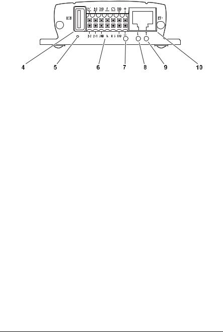
Rear panel connections
4USB interface
for future expansion of functions
5Factory-reset button
to restore default settings
6Terminal block
for alarm inputs, relay output, serial interface and power supply
7Operating status LED
flashes green when ready for operation
8LED L
lit green when the unit is connected to the network
9LED T
flashes orange when data is being transmitted over the network
10RJ45 jack ETH
for connecting to an Ethernet LAN (local network), 10/100 MBit Base-T
Further information on the LEDs can be found on page 93. Information about the pin assignment can be found on page 94.
Bosch Security Systems | 2005-05 | V1.0 |
Product description |

EN | 16 |
Installation and User Guide | VIP X1/VIP X2 |
|
|
Product description |
Bosch Security Systems | 2005-05 | V1.0 |

|
VIP X1/VIP X2 | Installation and User Guide |
EN | 17 |
|
|
|
|
|
|
Installation |
4 |
|
Thanks to its ultra-compact dimensions, the VIP X is particularly well suited for installation in cabinets.
 Warning!
The unit is intended for use indoors or in protected spaces. Select a suitable location for installation where the unit will not be subjected to conditions of extreme temperature or humidity. The ambient temperature must be between 0 and + 50 C (VIP X1) or between 0 and +40 C (VIP X2), relative humidity may not exceed 80 %.
The unit generates heat during operation. Ensure that there is adequate ventilation and also that there is enough clearance between the unit and heat-sensitive objects or equipment.
Please ensure the following conditions for installation:
]Do not mount the unit close to heaters or other heat sources. Avoid locations subject to direct sunlight.
] Allow sufficient space for running cables.
] Ensure that the unit has adequate ventilation.
]Use only the cables supplied for connections or appropriate cables resistant to electromagnetic interference.
]Position and run all cables so that they are protected from damage, and provide strain relief where needed.
] Avoid shocks, bashes and strong vibrations as they might destroy the unit.
Bosch Security Systems | 2005-05 | V1.0 |
Installation |

EN | 18 |
Installation and User Guide | VIP X1/VIP X2 |
|
|
Connections
Cameras
Depending on the device used, you can connect one (VIP X1) or two video sources (VIP X2). Any cameras or other video sources that produce a standard PAL or NTSC signal are suitable.
–Connect the cameras or other video sources with a video cable (75 Ohm, BNC connector) to the BNC jack Video In or to the jacks Video In 1 and
Video In 2.
Data interface
The bi-directional data interface is used to control devices connected to the VIP X, such as a dome camera with a motorized lens.
The interface supports the RS232, RS422 and RS485 transmission standards. The serial interface is made up of four terminals of the ST500 jack (for pin assignment see page 94).
The range of controllable devices is growing constantly. The manufacturers of this equipment can provide specific information on installation and control.
 Warning!
Refer to the device documentation when installing and operating a device to be controlled. This contains important safety instructions and information about permitted uses.
 Note
Note
A video connection is necessary to transmit transparent data.
Network
You can connect the VIP X to a 10/100 Base-T network. Use a standard UTP Category 5 cable with RJ45 connectors for this.
– Connect the unit to the network using the ETH jack.
Alarm inputs
The VIP X has four alarm inputs on the orange terminal block (for pin assignment, see page 94). The alarm inputs are used to connect to external alarm devices, such as door contacts or sensors. With the appropriate
Installation |
Bosch Security Systems | 2005-05 | V1.0 |

VIP X1/VIP X2 | Installation and User Guide |
EN | 19 |
|
|
configuration, an alarm sensor can, for example, trigger an automatic connection between the VIP X and a remote location.
A voltage free make contact or switch can be used as an actuator.
 Note
Note
If possible, use a bounce-free contact system as the actuator.
–Connect the lines to the appropriate terminals on the orange terminal block (IN1 to IN4) and check that the connection is secure.
Relay output
The VIP X has a relay output for switching external devices, such as lights or audible alarms. This relay output can be activated manually during an active connection with the VIP X. Moreover, the output can be configured to activate audible alarms or other devices as a response to an alarm signal. The relay output is also located on the orange terminal block (for pin assignment, see page 94).
 Warning!
The maximum rating of the relay contact is 30 V and 2 A.
–Connect the lines to the appropriate terminals (R) on the orange terminal block and check that the connection is secure.
Bosch Security Systems | 2005-05 | V1.0 |
Installation |

EN | 20 |
Installation and User Guide | VIP X1/VIP X2 |
|
|
Turning on/off
Mains connection
The VIP X includes a mains power supply with four primary adapters and terminal block. The VIP X does not have a power switch. The unit is ready for operation as soon as it is connected to the voltage feed.
 Warning!
To operate the VIP X, use exclusively the power supply unit supplied with the correct primary adapter for your mains socket. Use suitable equipment where necessary to ensure that the mains supply is free of interference such as voltage surges, spikes or voltage drops.
 Warning!
Connect VIP X to the mains only after everything else has been connected.
–Using the power supply unit cable, connect the terminal block to the orange jack on the VIP X.
–Ensure that the correct primary adapter is attached to the power supply unit and an appropriate mains socket is available.
–Plug the power supply unit into a grounded mains socket. The unit is ready for operation as soon as the "operating status" LED stops flashing red during start-up and is lit green.
If the network connection is in order, the green LED L is also lit. The flashing orange LED T indicates data traffic on the network.
Installation |
Bosch Security Systems | 2005-05 | V1.0 |
VIP X1/VIP X2 | Installation and User Guide |
EN | 21 |
|
|
Setup using a terminal program
Data terminal
You can connect a data terminal to the VIP X for setup and local control. The data terminal consists of a computer with terminal software. You can use the supplied configuration cable to make the connection (for pin assignment of the orange terminal block, see page 94).
HyperTerminal, a communications accessory included with Microsoft Windows, can be used as the terminal program.
 Note
Note
Information on installing and using HyperTerminal can be found in the user guides or online help for MS Windows.
–Before using the terminal program, disconnect the VIP X from the data network and disconnect the power supply unit from the mains socket.
–Connect the open lines of the configuration cable with the terminal block that is already connected to the power supply unit. The assignment can be seen from the labels on the configuration cable and the markings on the terminal block.
–Connect the terminal block with the orange socket on the unit.
–Connect the VIP X configuration cable with a free serial port on your computer.
–Ensure that the correct primary adapter is fitted and connect the power supply unit to an appropriate mains socket.
Configuring the terminal
To establish communication between the terminal program and the VIP X, the transmission parameters must be correctly defined. The following values should be set in the terminal program:
] 19,200 Bit/s
] 8 data bits
] No parity check
] 1 stop bit
] No protocol
Bosch Security Systems | 2005-05 | V1.0 |
Installation |

EN | 22 |
Installation and User Guide | VIP X1/VIP X2 |
|
|
Command entry
After the connection has been established, you must log on to VIP X. You can then access the main menu. You can call up additional submenus and functions using the on-screen commands.
–If necessary, turn off the local echo so that entered values are not repeated on the display.
–Enter only one command at a time.
–After entering a value (such as an IP address), re-check the entry before pressing the ENTER key to transfer the values to the VIP X.
Assigning an IP address
To operate the VIP X in your network, a network-valid IP address must be assigned.
The following default addresses have been pre-set at the factory: 192.168.0.1
–Start up a terminal program such as HyperTerminal.
–Enter the user name service. The main menu will be displayed.
–Enter the command 1 to open the IP menu.
–Enter 1 again. The current IP address will be displayed, and you will be requested to enter a new IP address.
Installation |
Bosch Security Systems | 2005-05 | V1.0 |

VIP X1/VIP X2 | Installation and User Guide |
EN | 23 |
|
|
–Enter the desired IP address and press Enter. The new IP address will be shown.
–Use the commands displayed for any additional settings required.
 Note
Note
The new IP address and a new subnet mask or gateway address will only be valid after restarting.
Restart
Briefly disconnect the power supply to the VIP X (disconnect power supply unit and re-connect after a few seconds).
Additional parameters
Using the terminal program, you can check other basic parameters and modify them where necessary. Use the on-screen commands displayed in the various submenus to do this.
Bosch Security Systems | 2005-05 | V1.0 |
Installation |

EN | 24 |
Installation and User Guide | VIP X1/VIP X2 |
|
|
Installation |
Bosch Security Systems | 2005-05 | V1.0 |

|
VIP X1/VIP X2 | Installation and User Guide |
EN | 25 |
|
|
|
|
|
|
Configuration using a Web Browser |
5 |
|
Connecting
The integrated HTTP server allows the unit to be configured over the network with a Web browser. This option is significantly more comprehensive and convenient than configuration using a terminal program and also offers you the option of displaying live video images.
 Note
Note
Make sure the graphics card is set to 16 or 32 bit colour depth and that Microsoft Virtual Machine is installed on your PC. If necessary, the required software and controls can be installed from the product CD provided (see Components supplied, page 9).
Instructions for using the Web browser can be found in its online help.
System requirements
] Microsoft Internet Explorer (version 6.0 or higher)
] Monitor resolution 1024 × 768 pixels
] Network access (Intranet or Internet)
 Note
Note
You should also take note of the information in the System requirements datasheet on the product CD supplied.
Install MPEG ActiveX
 Note
Note
In order to be able to play back live video images, an appropriate MPEG ActiveX must be installed on the computer. If necessary, the required software and controls can be installed from the product CD provided (see
Components supplied, page 9).
–Insert the CD into the CD-ROM drive of the computer. If the CD does not start automatically, open the root directory of the CD in Windows Explorer and double click MPEGAx.exe.
Bosch Security Systems | 2005-05 | V1.0 |
Configuration using a Web Browser |

EN | 26 |
Installation and User Guide | VIP X1/VIP X2 |
|
|
– Follow the on-screen instructions.
Establishing the connection
The VIP X must be assigned a valid IP address to operate on your network.
The following default addresses have been pre-set at the factory: 192.168.0.1
–Start the Web browser.
–Enter the IP address of the VIP X as the URL. The connection will be established and, after a short time, the LIVEPAGE with the video image will appear.
 Note
Note
Depending on whether you are using a VIP X1 or a VIP X2, the screen display may differ slightly from that shown above.
If the connection is not established, the maximum number of possible connections may already have been reached. The maximum number of connections depends on the device and network configuration.
Configuration using a Web Browser |
Bosch Security Systems | 2005-05 | V1.0 |

VIP X1/VIP X2 | Installation and User Guide |
EN | 27 |
|
|
Password protection in VIP X
If the VIP X is password-protected against unauthorized access, a corresponding message and a prompt to enter the password will appear when you attempt to access protected areas.
 Note
Note
A VIP X offers you the option of limiting access across various authorization levels (see pages 36 and 49).
–Enter the user name and associated password in the corresponding text fields.
–Click OK. If the password is correct, the desired page is displayed.
Choosing the configuration mode
There are two options for configuring the VIP X or checking the current setup:
] the unit overview or
] the configuration menu.
All settings are stored in the VIP X memory, and they are preserved even if the power is interrupted.
Unit overview
The unit overview shows the most important parameters summarized into six groups. This allows you to change the basic settings with just a few clicks and entries.
Configuration menu
The configuration menu is recommended for expert users or system administrators. All unit parameters can be accessed in this mode.
Changes that influence the fundamental functioning of the unit (for example firmware updates) can only be made using the configuration menu.
Bosch Security Systems | 2005-05 | V1.0 |
Configuration using a Web Browser |

EN | 28 |
Installation and User Guide | VIP X1/VIP X2 |
|
|
Beginning configuration
Click on the SETTINGS link in the upper section of the LIVEPAGE window. A new page containing the configuration menu (see Configuration menu, page 47) and the unit overview (see Unit overview, page 29) is opened.
 Note
Note
Depending on whether you are using a VIP X1 or a VIP X2, the screen display may differ slightly from that shown above.
Configuration using a Web Browser |
Bosch Security Systems | 2005-05 | V1.0 |

VIP X1/VIP X2 | Installation and User Guide |
EN | 29 |
|
|
Unit overview
The unit overview gives you a graphical overview of the individual areas of the configuration. The individual configuration parameters are grouped and displayed in separate windows. You can access the individual areas directly.
–Click one of the group graphics. A new window will open.
–Click in the text fields to enter values or use the other controls available, such as buttons, check boxes or list fields.
–Click on the SETTINGS link at the top of the window to close the window without saving the changes made.
Making changes
After making changes in a window, click the Set button to send the new settings to the unit and save them there.
 Warning!
Save the changes made in each window by clicking Set. Clicking the Set button always saves only the settings in the current window.
A description is given below of the individual windows that can be accessed using the graphical symbols in the overview.
Bosch Security Systems | 2005-05 | V1.0 |
Configuration using a Web Browser |

EN | 30 |
Installation and User Guide | VIP X1/VIP X2 |
|
|
Encoder settings
For encoding the video signal, you can select two profiles for each encoder (video input) and change the presets for the profiles.
Selecting a profile
You can adapt the MPEG-4 data transmission to the operating environment (for example network structure, bandwidth, data structures). To do this, the VIP X simultaneously generates two data streams (Dual Streaming) for each video input, for which you can select different compression settings, for example one setting for transmissions to the Internet and one for LAN connections.
 Note
Note
The settings must be made individually for each camera input and each stream. The designations Video 1 and Video 2 on the VIP X2 corresponds to the labeling of the video inputs on the actual unit.
Pre-programmed profiles are available, each giving priority to different perspectives.
]Profile 1: Low bandwidth (CIF)
High quality for low bandwidth connections, resolution 352 × 288/240 pixels
]Profile 2: Low delay (1/2 D1)
High quality with low delay, resolution 352 × 576/480 pixels
]Profile 3: High resolution (D1/4CIF)
High resolution for high bandwidth connections, resolution 704 × 576/480 pixels
Configuration using a Web Browser |
Bosch Security Systems | 2005-05 | V1.0 |
 Loading...