


DW REPAIIR IINSTRUCTIION
1 |
SAFETY .................................................. |
2 |
5.4 |
Heaters........................................................................ |
32 |
|
1.1 |
General hazards |
2 |
5.5 |
2-piece drain hose connection ................................. |
34 |
|
5.6 |
Drain pump removal and installation |
34 |
||||
1.2 |
Electrical shock / fire hazards |
2 |
||||
5.7 |
Door latch removal and installation |
34 |
||||
1.3 |
Plumbing / scalding hazards |
2 |
||||
6 |
FAULT DIAGNOSTICS |
36 |
||||
2 |
INSTALLATION |
3 |
||||
|
|
|
2.1 |
Pre-Install checklist ..................................................... |
|
3 |
2.2 |
Alignment ..................................................................... |
|
3 |
2.3 |
Electrical connection................................................... |
|
4 |
2.4 |
Water connection......................................................... |
|
4 |
2.5 |
Drain and condensati |
ections............... |
5 |
6.1Customer service
6.2 |
Troubleshooting......................................................... |
38 |
7 |
TECHNICAL SPECIFICATIONS .......... |
42 |
|
test pr |
|
3 |
OPERATION........................................... |
6 |
ogram ................................ |
36 |
3.1 |
Control layout............................................................... |
6 |
|
|
3.2 |
Reset (“Cancel – drain”).............................................. |
7 |
|
|
3.3 |
Changing basic features (on selected units)............. |
7 |
|
|
|
on hose conn |
|
|
|
3.4Entering special programs and c
3.5Dispen
|
4 |
COMPONENTS |
..................................... oding .. .. .. .. ... 7 |
9 |
10 |
|
|
|
ser...................................................................... |
|
|
|
|
|
4.1 |
Dishwasher components........................................... |
|
10 |
|
|
|
4.2 |
Operation .................................................................... |
|
|
26 |
|
|
4.3 |
Serial label (warranty ...........................information) |
|
26 |
|
|
|
5 |
REPAIR................................................. |
|
|
28 |
|
|
5.1 |
Water valves ............................................................... |
|
|
28 |
|
|
5.2 |
Circulation pumps...................................................... |
|
|
28 |
|
|
5.3 |
Controls ...................................................................... |
|
|
31 |
|
|
|
|
|
|
|
|
|
|
|
|
|
|
|
|
702_58300000148618_ara_en_a |
|
|
Page 1 of 42 |
|
|
Downloaded from www.Manualslib.com manuals search engine

1 |
SAFETY |
|
|
|
|
1.1 |
General hazards |
m |
|
|
|
Don’t use the dishwasher until it is completely installed. When opening the door on an uninstalled dishwasher, carefully open the door while supporting the rear of the unit. Failure to follow this warning can cause the dishwasher to tip over and result in serious injury.
In some conditions, hydrogen gas can form in a hot water system that has not been used for weeks. Hydrogen gas is explosive. Before filling a dishwasher from a system that has been off for weeks, run the water from a nearby faucet in a well ventilated area until there is no sound or evidence of gas.
Temperatures required for sol
the dishwasher’s base and water inlet valve. If plumbing lines are to be soldered or sweated, keep the heat source at least 6 inches (152.4 mm) away from the dishwasher’s base and water inlet valve.
Removing any cover or pulling the dishwasher from the cabinet can expose hot water connections, electrical power and sharp
edges or points. Handle with care |
|
|
glasses. |
|
|
dering and sweating will damage |
c h |
|
1.2 |
Electrical shock / fire hazards |
|
Don’t allow electrical and water supply lines to touch. Don’t work on an energized circuit. Doing so could result in serious injury or death. Only qualified electricians should perform electrical work. Don’t attempt any work on the dishwasher electric supply circuit
until you are certain the circuit is de-energized.
. Always wear gloves and safety
Make sure electrical work is properly installed. There should be no loose electrical connections. Ensure all electrical connections are properly made.
702_58300000148618_ara_en_a
The customer has the responsibility of ensuring that the dishwasher electrical installation is in compliance with all national and local electrical codes and ordinances. The dishwasher is designed for an electrical supply of 120VAC, 60 Hz, connected to a dishwasher-dedicated, properly grounded electrical circuit with a fuse or breaker rated for 15 amps. Electrical supply conductors shall be a minimum #14 AWG copper only wire rated at 75°C (167°F) or higher.
This appliance must be connected to a grounded metal, permanent wiring system, or an equipment-grounding conductor must be run with the circuit conductors and connected to the equipment-grounding terminal or lead on the appliance. Don’t use extension cords.
1.3 Plumbing / scalding hazards |
m |
|
|
Don’t perform any work on a charged hot water line. Serious injury could result. Only qualified plumbers should perform plumbing work. Don’t attempt any work on the dishwasher hot water supply plumbing until you are certain the hot water supply is shut off.
Don’t over tighten the 90° elbow. Doing so may damage the water inlet valve and cause a wate
for soldering and sweating will damage the dishwasher’s water inlet valve. If plumbing lines are to be soldered or sweated, keep the heat source at least 6 inches (152.4 mm) away from the dishwasher’s water inlet valve.
Check local plumbing codes for approved plumbing procedures and accessories. All plumbing should be done in accordance with national and local codes.
These instructions depict an installation method for stainless steel
braided hose or PEX hot water supply lines. If using copper r leak. Temperatures required
tubing or other material for water supply, defer to a licensed plumber for proper installation.
Page 2 of 42
Downloaded from www.Manualslib.com manuals search engine
2 INSTALLATION
2.1Pre-Install checklist
□Unpack unit. Retain packing material until installation is successful. Remove packing material from inside the dishwasher.
□Inspect parts to ensure you have all the necessary materials.
□Flush household hot water supply for at least two minutes.
□Measure the enclosure area. The opening must be at least 34" (87 cm) high and 23-5/8" (60-61 cm) wide.
□The opening must be close enough to the sink for water line and drain hose plumbing access.
□Unit must be installed close enough to the sink so that drain hose length does not exceed 92" (234 cm) and a high loop is raised at least 20" (51 cm) above the floor.
□Wooden openings must be sanded smooth and metal openings must be covered by a protective gasket.
□Is your water heater set at 120°F (49°C) and does water pressure measure 15-145 psi (1-10 bar)?
□If installing in a corner, the dishwasher door must clear cabinet hardware.
□Determine mounting method based on dishwasher model and countertop type, whether top or side mount.
2.2Alignment
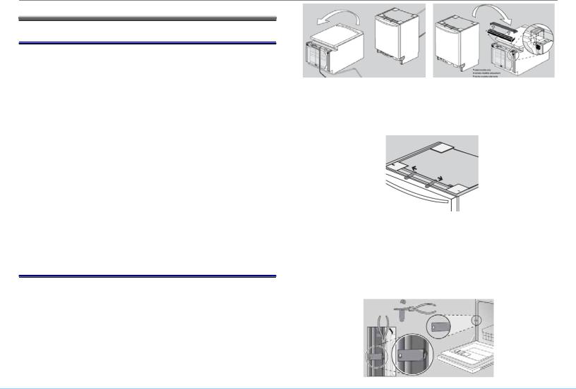
Gently rest the unit on its back, taking care not to crush the drain hose. Remove the toe panel(s). Loosen front feet slightly. Remove junction box cover and retain for later use. Place dishwasher upright, then level side to side and front to back.
If your dishwasher has pre-attached mounting brackets and you have a wooden under-counter, position brackets as far apart as possible by sliding them within slots in direction of arrows. Do not attach them to the countertop yet.
If your dishwasher has pre-attached mounting brackets and the counter top is stone, use pliers to rotate bracket flanges to remove brackets from the top. Grasp brackets with pliers at perforation and bend until the rounded end breaks free. Discard the ends. Slip brackets through side slots. Using pliers, bend bracket flanges so the brackets will not slip through slots. Do not attach them to the countertop yet.
702_58300000148618_ara_en_a |
Page 3 of 42 |
Downloaded from www.Manualslib.com manuals search engine

2.3Electrical connection
Install according to national and local codes.
Carefully place dishwasher on its back to make electrical connections to the terminal block. Turn power off at the fuse box. Extend power cord approximately
opening, and 30” from the back wall, making sure the cord doesn’t contact any moving parts.
Strip outer casing of electrical wire to expose 2.5" - 3" (65 - 76 mm) of inner wires, then strip 1/2" (13 mm) casing from each wire. If plugging the dishwasher
service to order power cord accessory kit (SGZPC001UC). Insert cord through a strain relief (not included) and install to strain relief plate. Attach wires to terminal block (black – L (hot), white – N
(neutral) & green – G (ground). Unscrew terminal screws, but 21” from the left side of the
don’t loosen or remove them as they may become damaged. Attach wires snugly, but don’t overtighten.
into an
2.4Water connection
Install according to national and local codes.
Carefully place dishwasher on its back to make water connections to the water inlet valve. Use a 90º elbow fitting with Teflon tape as needed. Don’t overtighten.
Attach the hot water line to the 90° elbow and route it underneath the unit toward the hot water connection. Make sure the line doesn’t contact any moving parts.
702_58300000148618_ara_en_a |
Page 4 of 42 |
Downloaded from www.Manualslib.com manuals search engine

2.5Drain and condensation hose connections
Plumbing installations will vary - refer to local codes. The maximum length of the drain hose, including leading to an air gap (if any) is 150" (381 cm). Make sure a high loop is raised at least 20" (51 cm) above the floor.
Drain hose has its own adapter – connect directly to plumbing connection and secure with supplied hose clamp. Don’t connect to condensation hose.
702_58300000148618_ara_en_a
Downloaded from www.Manualslib.com manuals search engine
Page 5 of 42

3 OPERATION
3.1Control layout
3.1.1SHE models
SHE55P
SHE43P15
SHU66C
702_58300000148618_ara_en_a
3.1.2SHX / SHV models
SHX46A
SHV66A
3.1.3Features
The Sanitized light comes on after certain wash programs have finished, showing dishes have been sanitized according to NSF standards. Check the Use & Care manual for your model to confirm which programs qualify as NSF rated.
The Refill Rinse Agent light shows rinse-aid needs to be added.
Page 6 of 42
Downloaded from www.Manualslib.com manuals search engine
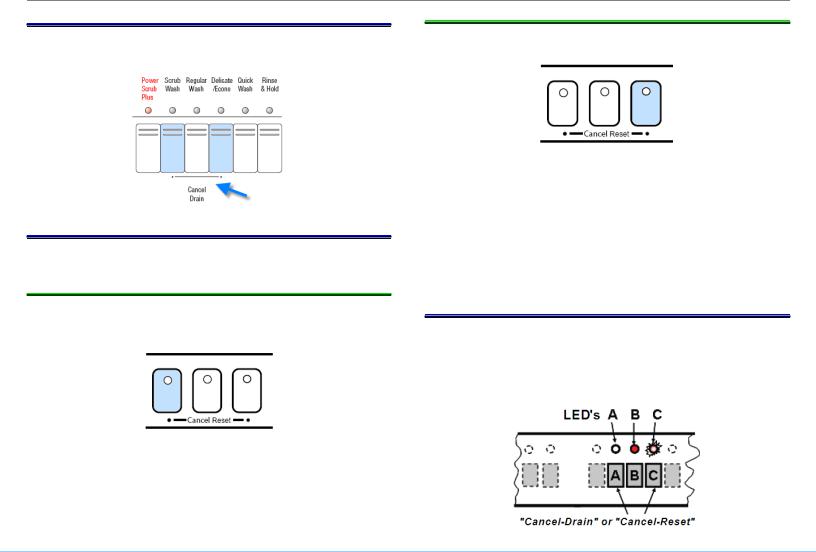
3.2Reset (“Cancel – drain”)
To reset, push Cancel-Drain or
time. Cancel-Reset
3.3Changing basic features (on selected units)
On some models, features can be changed on the fascia panel.
3.3.1Extra dry heat
With Extra Dry Heat, the temperature of the rinse water can be raised and the drying time increased for improved drying.
Turn the dishwasher off and then push and hold the left Cancel Reset button while turning the dishwasher on – release buttons when the display shows “0” or “1”.
Pushing the left Cancel Reset button changes the setting – choose “1” to turn it on and choose “0” to turn it off. Push the on/off button to save the setting.
702_58300000148618_ara_en_a
3.3.2End of cycle tone
The End of cycle tone volume can also be changed.
Turn the dishwasher off and then push and hold the right Cancel Reset button while turning the dishwasher on – release buttons when a tone sounds or the right Cancel Reset button LED lights up.
Pushing the right Cancel Reset button changes the setting – push it until the tone is at the desired volume (or the tone stops if it’s to be turned off). Push the on/off button to save the setting.
3.4Entering special programs and coding
Controls contain codes for sales demo mode, factory tests, customer service test program, dishwasher configuration and error codes. Consult test programs and error codes for your dishwasher before using the codes listed in this manual.
Page 7 of 42
Downloaded from www.Manualslib.com manuals search engine

While pushing (and holding) any two wash cycle buttons, turn the dishwasher on with the on/off switch. The current coding (e.g. “C1”) will show in the display or LED's until you release the buttons. After releasing the buttons, LED “B” will be lit and LED “C” will flash, confirming you’re in the special programs menu. Push button “B” repeatedly until you’ve selected your desired program (see P(X) Program codes, “P1” or “ ” -- programs “P0”
and “P3” are factory tests that aren’t to be used).
P4
The following typical codes cover most dishwashers. Consult the test program for your model to confirm the codes to use.
3.4.1Typical P(X) Program codes
P0 = Functional test - used for assembly (do not use)
P1 = Customer service test program (see E(X) error codes) P3 = Endurance / Life test (do not use)
P4 = Control coding (see C(X) control codes)
3.4.2Typical E(X) Error codes
E0 = No errors
E1 = Heating error
E2 = NTC error
E3 = Filling error
E4 = Water switch cannot be positioned
E5 = Safety float water level reached or motor speed error (error code dependent on model – check test program)
E6 = Aqua sensor error
3.4.3Typical C(X) Control codes
C9 = Sales demo mode
Codes C1 through C9 are possible, depending on the model.
HINT: Customers pushing and holding Cancel-Drain or CancelReset buttons while turning dishwashers on can see strange
702_58300000148618_ara_en_a
displays. Whenever you get call about a “strange” display, check if the customer put the dishwasher into the test program or some other program.
3.4.4Sales demo (showroom) program
3.4.4.1Entering sales demo program
Enter the special program mode – see section 3.5. Before releasing the two buttons held while you turned the dishwasher on, note the coding on the digital display (e.g. “C1”, “C2”, etc) -- the dishwasher must be returned to this code for resale.
Push button “B” repeatedly until the display shows sales demo program mode “P4”. Push button “C” to confirm it.
Push button “B” repeatedly until the display shows sales demo code “C9”. Push button “C” to confirm it.
Turn power off and then back on. The dishwasher is now in demo mode -- all button lights will light up.
3.4.4.2Preparing a dishwasher for showroom use
1.Turn off the power to the dishwasher or disconnect the dishwasher from the electrical power.
mWARNING: Danger of electrical shock!
2.Remove the toe kick and locate the drain pump terminal shown below. Disconnect the terminal from the drain pump by squeezing and pulling it out. Cover the terminal with electrical tape to prevent electrical shock.
Page 8 of 42
Downloaded from www.Manualslib.com manuals search engine
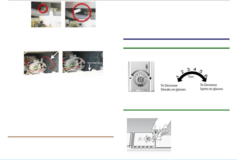
3.Disconnect both ends of the short heater red
section 5.2.3 to remove right side panel for wireaccess– .seeTape the wire with electrical tape to the plastic base so it can be reconnected for resale.
4.Do NOT connect dishwasher to a water line, but slowly pour about 4.5 liters of distilled water into the tank. The
water level should be near the bottom of the fine filter screen in the sump.
5.Add a small amount of ri
antibacterial agent (bacteriastat) onto the inner door. Do NOT add bleach.
6.Reconnect the dishwasher and turn it on by pushing the on/off button. Close the door and run dishwasher for one
minute. If necessary, add more water until level reaches the fine filter screen.
3.4.4.3 Preparing a showroom dishwasher for resale nse aid and a 1/2 capful of
To return the dishwasher back to it’s original condition for resale, enter the special program mode – see section 3.4. Push button “B” repeatedly until the display shows sales demo program mode “P4”. Push button “C” to confirm it.
702_58300000148618_ara_en_a
Push button “B” repeatedly until the display shows the original dishwasher code (e.g. “C1”, “C2”, etc). Push button “ ” to confirm it.
Turn power off and then back on. The dishwasher now has it’s original coding. Reconnect the pump and heater that was previously disconnected.
3.5 |
Dispenser |
C |
|
|
3.5.1Adjusting rinse-aid dosage
The amount of rinse-aid can be adjusted at the dispenser.
Rinse-aid can be added by pouring it onto the arrow.
3.5.2Closing dispenser doors
1. Slide cover fully left.
2. Push back end of the cover (onto the arrow) down firmly until you hear a click.
Page 9 of 42
Downloaded from www.Manualslib.com manuals search engine

4 COMPONENTS
4.1Dishwasher components
4.1.1Tank
The tank, made of 304 stainless steel part.
, isn’t available as a service
4.1.2 Leveling feet (front and rear)
The base is supported by three leveling feet, two front and one rear. The rear leveling foot is adjusted from the front. Front feet have provisions for set screws (in installation parts bag).
702_58300000148618_ara_en_a
4.1.3Heater
4.1.3.1Operation
Bosch dishwashers use flow-through heaters instead of exposed elements, saving space and allowing taller tanks holding larger dinner plates. Flow-through heaters prevent dishware damage from exposed elements and allow water to be continuously filtered and heated.
Seal |
Heating element |
NTC/Hi-limit
Flow switch
To upper spray arm
To lower |
From circulation pump |
spray arm |
|
Filtered water from the sump flows through the circulation pump into the flow-through heater. All heaters are protected by a 185ºF Hi-limit (high temperature cutout) and by a flow switch which prevents heaters from operating when no water is flowing.
4.1.3.2Heater ratings
120 VAC, 60 Hz, 1200 W
Heats water about 2ºF / minute
Page 10 of 42
Downloaded from www.Manualslib.com manuals search engine
4.1.3.3Softer bearing (UC/11 and later)
Softer bearing (UC/11 and later) & non-softer bearing (UC/06) heater assemblies, circulation pumps and sumps cannot be mixed and matched. Softer bear
models and older heaters don’t fit in softer bearing models.
Softer bearing & non-softer bearing heater assemblies are connected to circulation pumps differently:
•Softer bearing models (UC/11 & above) have gasket
assembled to heater and have a separate hose clamp (order # ).
•Older models (UC/06) have a separate gasket and do
not172272have a hose clamp. ing heaters don’t fit in older
4.1.3.4Top Rack Only
Models with Top Rack Only have separate actuators mounted underneath heater assemblies. The actuator moves a magnetic float to block the lower rack port, diverting water to the top rack.
|
|
|
|
|
|
|
|
|
|
Lower |
|
|
Lower spray arm |
|
|
spray arm |
|||||||
|
|
|
|
|
|
|
|
|
|
|
|
|
|
|
|
|
|
|
|
|
|
|
|
|
|
|
|
|
|
|
|
|
Magnetic |
||
|
Magnetic float |
|
|
|
|
|
|||||
|
|
|
|
|
|
float |
|
||||
|
|
|
|
|
|
|
|
|
|||
|
|
|
|
|
|
|
|
|
|
|
|
|
|
|
|
|
|
|
|
|
Magnet |
||
|
|
Magnet |
|
|
|
|
|
||||
|
|
|
|
|
|
|
|||||
|
|
|
|
|
|||||||
Actuator (hot |
Actuator (hot |
||||||||||
wax motor) |
|
|
wax motor) |
|
|||||||
The actuator moves a magnet under the magnetic float so the north poles align, repelling the
blocks the water flow to the lower spray arm.
Heater with top rack housing |
|
Both racks |
|
Top rack only |
702_58300000148618_ara_en_a |
Page 11 of 42 |
Downloaded from www.Manualslib.com manuals search engine
Top view
Plunger
Bottom view
Where plunger engages heater |
Where plunger engages sump |
4.1.3.5Half Load
Starting with UC/33 dishwashers, Half Load replaced Top Rack Only. Like , it uses 30% less water, saving water and energy. Unlike Top Rack Only with mechanical actuators, Half LoadTop Rackis doneOnlyby control software (through shortening cycles) and doesn’t limit water flow to the top rack.
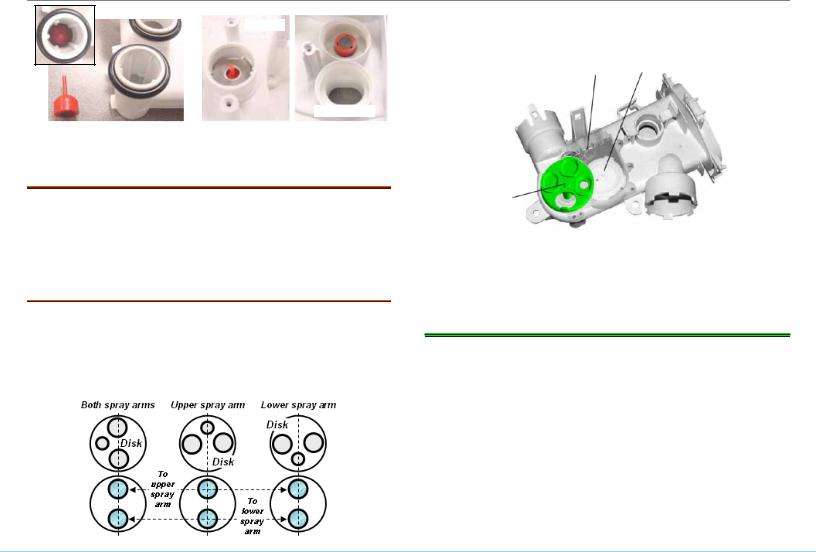
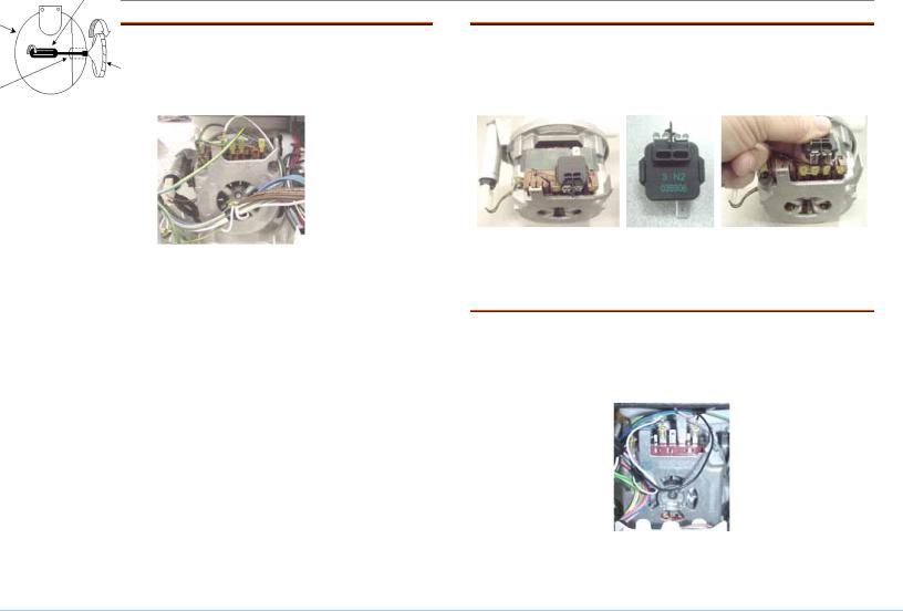
4.1.3.6Water switch
Motor operated water switches
assemblies. They consist of a motor-controlled disk with 3 holes which rotates and lines up over two sump ports (upper / lower spray arms) to provide precise water control to upper, lower or both spray arms.
are
702_58300000148618_ara_en_a
Models with water switches & Top Rack Only use water switches to divert water. Separate actuators aren’t needed.
Microswitch Cam
European disk shown, which is different than U.S. disk
Disk
Models with water switches need stronger circulation pumps (# 437345) with separate motor starters (# 182318). Circulation pumps, heaters & sumps for water switch / non-water switch models can’t be interchanged.
4.1.4Circulation pumps
Bosch dishwashers use separate circulation and drain pumps to reduce overall size, noise, vibration and energy consumption. This allows the use of tall tanks, increasing overall space inside dishwashers where full-sized plates can be placed in both upper and lower racks. Circulation pumps are suspended by rubber straps to further reduce noise and vibration.
Depending on features, dishwashers have one of four types of circulation pumps. Pumps use different controls, wire harnesses, heaters & sump filters, so replace with identical replacement pumps.
Page 12 of 42
Downloaded from www.Manualslib.com manuals search engine
4.1.4.1“Sisme” (UC/06 through UC/23)
It has a capacitor start motor with a centrifugal switch cutting out the starting capacitor once the motor comes up to speed. This pump can be replaced as # 239144 pump assembly, # 266511 motor only or # impeller kit.
167085
It has a ceramic seal keeping water from entering the motor and an 8mm nut on the impeller to free it if it should ever stick.
8mm nutdriver
Sump |
|
Sump |
Impeller |
|
|
access to |
|
impeller |
|
4.1.4.2“Sisme” pump with PTC motor starter
Pump # 437345 pump is more powerful for use with heaters with water switches and sumps with extra filter cylinder. It uses a separate motor starter (# 182318) attached to the motor terminals. It can use # 167085 impeller kit.
The (PTC) circulation pump moto |
ter cuts out the start |
winding after the motor starts. |
|
4.1.4.3“Sicasym” (UC/21 through present)
Most common pump (used starting with UC/21 index). Smaller than 239144 “Sisme” pump. Used with controls & single wire harnesses designed for Sicasym pumps. Motor controls have motor starter software, so there
r star
are no mechanical starters There is no impeller kit.
702_58300000148618_ara_en_a |
Page 13 of 42 |
Downloaded from www.Manualslib.com manuals search engine
 Loading...