


Bosch SHSM63W55N, SHPM65W52N, SHP865WD6N, SHEM63W56N, SHEM63W52N Installation Manual
...Installation Instructions Notice d’installation Instrucciones de instalación
9001244446 Rev A. (9609)

Important Safety Instructions: Please READ and SAVE this information
To avoid possible injury or property damage, OBSERVE ALL WARNINGS AND CAUTIONS.
These instructions are intended for use by qualified installers only. The dishwasher must be installed by a qualified service technician or installer.
•In addition to these instructions, the dishwasher shall be installed to meet all electrical and plumbing codes and ordinances (both national and local).
Read these installation instructions completely and follow them carefully. They will save you time and effort and help to ensure safety and optimum dishwasher performance.
IMPORTANT
•The dishwasher drain hose must be installed with a portion of it at least 20″ (508 mm) off the cabinet floor; otherwise the dishwasher may not drain properly.
•This dishwasher is intended for indoor residential use only, and should not be used in commercial food service establishments.
•This dishwasher is designed to be enclosed on the top and both sides by cabinetry.
•NEW INSTALLATION - If the dishwasher is a new installation, ensure all connections are properly made before the dishwasher is moved into place.
•REPLACEMENT - If the dishwasher is replacing another dishwasher, check the existing dishwasher connections for compatibility with the new dishwasher, and replace parts as necessary.
•ThisappliancehasbeenfoundtobeincompliancewithCAN/CSA-C22.2 No. 167/UL 749. It is the responsibility of the owner and the installer to determine if additional requirements and standards apply in specific installations.
•Not for outdoor use.
Inspect the Dishwasher
After unpacking the dishwasher and prior to installation, thoroughly inspect the dishwasher for possible freight or cosmetic damage. Report any damage immediately. Cosmetic defects must be reported within 30 days of installation.
NOTE: Do not discard any bags or items that come with the original package
until after the entire installation has been completed.
1
 WARNING
Avoiding General Hazards
Do not use the dishwasher until it is completely installed. When opening the door on an uninstalled dishwasher, carefully open the door while supporting the rear of the unit. Failure to follow this warning can cause the dishwasher to tip over and result in serious injury.
Before installing the supplied counter top mounting brackets, decide which method will be used to secure the dishwasher into its opening. Once these mounting brackets are installed on the dishwasher, removing them is difficult and will damage the mounting brackets and the dishwasher.
In some conditions, hydrogen gas can form in a hot water system that has not been used for weeks. Hydrogen gas is explosive. Before filling a dishwasher from a system that has been off for weeks, run the water from a nearby faucet in a well ventilated area until there is no sound or evidence of gas.
Removing any cover or pulling the dishwasher from the cabinet can expose hot water connections, electrical power and sharp edges or points. Handle with care.
Avoiding Electrical Shock/Fire Hazards
Do not work on an energized circuit. Doing so could result in serious injury or death. Only qualified electricians should perform electrical work.
Do not attempt any work on the dishwasher electric supply circuit until you are certain the circuit is de-energized.
Make sure electrical work is properly installed. There should be no loose electrical connections. Ensure all electrical connections are properly made.
The customer has the responsibility of ensuring that the dishwasher electrical installation is in compliance with all national and local electrical codes and ordinances. The dishwasher is designed for an electrical supply of 120V, 60 Hz,AC, connected to a dishwasher-dedicated, properly grounded electrical circuit with a fuse or breaker rated for 15 amps. Electrical supply conductors shall be a minimum #14 AWG copper only
wire rated at 75°C (167°F) or higher.
2

This appliance must be connected to a grounded metal, permanent wiring system, or an equipment-grounding conductor must be run with the circuit conductors and connected to the equipment-grounding terminal or lead on
the appliance. Do not use extension cords.
Avoiding Plumbing/Scalding Hazards
Do not perform any work on a charged hot water line. Serious injury could result. Only qualified plumber should perform plumbing work. Do not attempt any work on the dishwasher hot water supply plumbing until you are certain the hot water supply is shut off.
Properly tighten all water connections. Not doing so could result in a leak.
Temperatures required for soldering and sweating will damage the dishwasher’s base and water inlet valve. If plumbing lines are to be soldered or sweated, keep the heat source at least 6″ (152.4 mm) away from the dishwasher.
Check local plumbing codes for approved plumbing procedures and accessories. All plumbing should be done in accordance with national and local codes.
If using copper tubing or other material not depicted in this manual for water supply, defer to a licensed plumber for proper installation.
3

Tools and Materials Needed
|
|
|
|
Adjustable Wrench |
Drill |
Hole Saw |
Tape Measure |
Wire Cutter |
Wire Stripper |
Pliers |
Needle Nose Pliers |
Phillips Screwdriver |
Slot Screwdriver |
Level |
90° elbow with 3/4" N.P.T. female threads on one leg, and sized to fit your water supply line (copper tubing/ compression fitting, or braided hose) on the other leg.
Electrical Supply Cable - Minimum #14 AWG, 2 conductor, 1 ground, insulated copper conductors rated 75°C or higher
Hot Water Supply Line - Minimum 3/8″ O.D. copper tubing or metal braided dishwasher supply line
Shut-off valve and fittings appropriate for hot water supply line (copper tubing/compression fitting, or braided hose
UL listed conduit connector or strain relief is required if you attach the field wiring directly to the terminal bloc
4

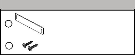
Materials supplied
A |
Junction Box |
|
B |
Edge Protector |
|
C |
Screw Clamp (for drain hose) |
|
D |
Mounting Brackets |
|
E |
Mounting Bracket Screws Ø 4x13mm |
F |
Adhesive Backed Cord Clip |
|
5
Materials supplied
G |
Slotted Toe Panel |
H |
Slotted Toe Panel Screws Ø 4x16mm |
6

Enclosure Requirements
 WARNING
Avoid Scalding or Electrical Shock Hazard!
Make sure the water supply and electrical supply are shut off before installation or service.
1 |
3.6 |
Note: This dishwasher is designed to be enclosed on the top, back and both sides by standard residential kitchen cabinetry.
Select a location as close to the sink as possible for easy access to water supply and drain lines.
For proper dishwasher operation and appearance, ensure that the enclosure is square and has the dimensions shown.
2 |
|
|
|
|
|
|
|
|
|
|
|
If the dishwasher is to be installed in a corner, ensure that there is
adequate clearance to open the door as shown. |
7 |
|

3 |
|
|
|
|
|
|
|
|
|
||
|
|
|
|
|
|
|
|
|
|
|
|
|
|
|
|
|
|
|
|
After locating the proper place for your dishwasher, create required openings in your cabinets in order to allow for water, drain and electrical lines on the appropriate side. The holes should be cut within the 4x2.5” area shown.
4
B
If the opening is made through wood, sand it smooth. If the opening is made through metal, use the provided edge protector (B) or other approved method to protect wiring from damage.
8

5 |
Pull the drain hose out of the packaging base as shown.
Set toe panel aside for later use.
6 |
Attach 90° elbow joint to dishwasher oriented as shown. Do not over-tighten.
Attach hot water line to 90° elbow.
9

7 |
Remove the hose clip at the back of the dishwasher as shown. The hose clip may be used later to hold the drain hose inside your cabinet.
Electrical Preparation
 WARNING
Avoid Electrical Shock Hazard
Donotworkonanenergizedcircuit.Doingsocouldresultinserious injury or death. Only qualified electricians should perform electrical work. Do not attempt any work on the dishwasher electric supply circuit until you are certain the circuit is de-energized.
To avoid possible injury or property damage, care should be exercised when the dishwasher is installed or removed to reduce the likelihood of damage to the power cord.
Avoid Fire Hazard
Make sure electrical work is properly installed. Only qualified electricians should perform electrical work.
Make sure there are no loose electrical connections. Make sure all electrical connections are properly made.
Electrical Supply
The customer has the responsibility of ensuring that the dishwasher electrical installation is in compliance with all national and local electrical codes and ordinances. The dishwasher is designed for an electrical supply of 120V, 60 Hz, AC, connected to a dishwasher-dedicated, properly grounded electrical circuit with a fuse or breaker rated for 15 amps. Electrical supply conductors shall be a minimum #14 AWG copper wire
10 rated at 75°C (167°F) or higher.
Dishwasher Electrical Rating
Volts |
Hertz |
Amperes |
Watts |
|||
|
|
|
|
|
|
|
|
|
|
|
|
|
|
120 |
60 |
12 |
1,4450 |
|
||
(max) |
||||||
|
|
|
||||
|
|
|
|
|
|
|
Grounding Instructions
The dishwasher must be properly grounded before operating. This appliance must be connected to a grounded metal permanent wiring system or an equipment grounding conductor must be run with the circuit conductors and connected to the equipment grounding terminal or lead on the dishwasher. Make sure that the dishwasher is connected to a suitable ground in compliance with all local codes or, in the absence of a local code, with the NATIONAL ELECTRICAL CODE in the United States or the CANADIAN ELECTRIC CODE C22.1-latest edition in Canada as well as any
provincial/state or municipal or local codes that apply.
Note: Installations employing a Receptacle
The accessory cord kit (Model # SMZPC002UC) designed for connection to a receptacle is not provided, but can be ordered through Customer Service by calling 1-800-944-2904. Make sure the household receptacle meets the electrical supply requirements as well as national and local codes. If you choose to permanently connect to hardwiring, follow the next steps.
8
|
|
|
|
|
|
|
|
|
|
||
|
|
|
|
Turn off any electricity to installation area.
Removescrewsandcover from junction box (A) and set aside for later use .
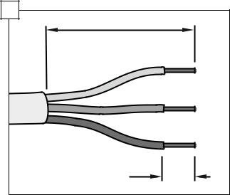
Remove outer casing and insulation of the hardwiring/power cord as shown.
11

9
ADVERTENCIA |
|
ESTRICTAMENTE SIGA TODAS LAS INSTRUCCIONES DE ESTE MANUAL. |
arrow |
NO SON EXTRAIBLES. |
|
UTILICE SÓLO EL 14 O 12 DE ALAMBRE DE COBRE AWG CON UN GRADO |
|
DE LA TEMPERATURA MÍNIMA DE 75 ° C (167 ° F). |
|
COLOQUE TODOS LOS CABLES EN LA CAJA DE LA FUENTE DE ALIMEN- |
|
TACIÓN Y LA INSTALACIÓN DE LA CUBIERTA. TORNILLOS DE CONEXIÓN |
|
1/2" (13 mm) |
|
WIRE STRIP GAGE |
|
CALIBRE DE POUR DÉNUDER |
|
INDICADOR DE CABLE PELADO |
|
WARNING |
|
STRICTLY FOLLOW ALL INSTRUCTIONS IN THIS MANUAL. |
|
USE ONLY 14 OR 12 AWG COPPER WIRE WITH A MIN. TEMP. RATING |
|
OF 75°C (167°F). |
|
PLACE ALL WIRING IN THE POWER SUPPLY BOX AND INSTALL COVER. |
|
CONNECTION SCREWS ARE NOT REMOVABLE. |
|
AVERTISSEMENT |
|
OBSERVER TOUTES LES INSTRUCTIONS DE CE GUIDE. |
|
UTILISER SEULEMENT DU FIL DE CUIVRE 14 OU 12 AWG AVEC UNE |
|
COTE DE TEMPÉRATURE MINIMALE DE 75°C (167°F). |
|
PLACER TOUS LES FILS DANS LA BOÌTE D‘ALIMENTATION ET |
|
REMETTRE LE COUVERCLE. |
|
LES VIS DE CONNEXIONS NE SONT PAS AMOVIBLES. |
|
view with cover installed
A
strain relief (not provided)
Attach strain relief (not provided) to opposite side of junction box.
Note: The arrow (shown in the figure above) should align with the power cord.
Insert the bare copper or green wire (ground) from the field supply wiring into the ground connection “  ” of the terminal block and securely tighten the terminal block screw as shown.
Insert the white (neutral) wire to the “N” connection of the terminal block and securely tighten the terminal block screw.
Insert the black (hot) wire to the “L” connection of the terminal block and securely tighten the terminal block screw.
Tighten strain relief.
12

10
A |
Mount the dishwasher electrical supply junction box (A) and dedicated receptacle in an accessible cabinet adjacent to the dishwasher (do not mount the junction box or receptacle behind the dishwasher).
Note: screws are not provided for mounting electrical supply junction box.
11 |
|
|
CLICK |
|
|
5" |
(127 mm) |
Leg Adjuster |
|
||
Adhesive |
|
|
backed |
|
|
cord clip |
|
|
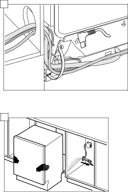
Check all electrical connections to ensure they are secure and then reattach the junction box cover.
Placeadhesivebackedcordclip (provided in the installation kit) 5 inches from leg adjuster as shown in the figure above and route power cord through the clip.
Note: The length of cord measured from the plastic back strap to the receptacle should be ≤ 47.25" (1,200 mm).
Plug the end of the supply cord into the back of the dishwasher as shown until it clicks.
13

Installation of Mounting Brackets
NOTICE
Beforeinstallingthesuppliedcountertopmountingbrackets,decide which method of securing the dishwasher into its enclosure will be used. Once the mounting brackets are installed on the dishwasher, removing them is difficult and will damage the mounting brackets and the dishwasher.
If you have a Fully Integrated Panel, donot attach mounting brackets until after attaching the panel to the door.
 WARNING
Avoid Tip Over Hazard
Do not use the dishwasher until it is completely installed. When opening the door on an uninstalled dishwasher, carefully open the door while supporting the rear of the unit. Failure to follow this
warning can result in serious injury.
12 |
|
|
|
|
|
Top Mount is used for counter tops made of wood or other materials that can be easily drilled. If you have solid surface, marble, granite, or other very hard countertops, skip to step 13 now.
If insulation is covering the area in 12a, fold it back.
Orient the mounting brackets (D) as shown. Please note the positioning of the bracket in illustration 12b.
Using pliers, bend down as shown in 12c such that the bracket will not
14 slip out of slot in frame. Do not attach to cabinet yet.

13 |
|
|
|
|
|
Side Mount is used for counter tops made of marble, granite, or other very hard materials that cannot be easily drilled.
Grasp mounting bracket (D)with pliers at perforation and bend until rounded end breaks free. Discard end.
Slip bracket flange through side slots in frame as shown. Using pliers, bend flange such that the bracket will not slip out of slot. Do not attach to cabinet yet.
15

Positioning the Dishwasher
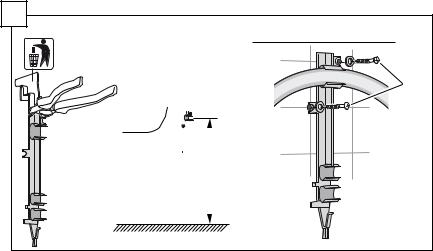
14 |
If your sink is to the right side of where you are installing the dishwasher, you will need to reposition the hoses behind the dishwasher before installing.
To do so, unhook the strap that the hoses are running through on the back of the dishwasher base and position them per your requirements.
If your sink is to the left side, leave the hoses as they came and skip to step 16.
16
15 |
Reposition the hoses such that they run through the strap on the other side.
Be sure to snap the strap back in place to secure the hoses as shown.
16 |
To avoid scratching the floo , use floor protection and caution when sliding the dishwasher into the cabinet. Use hands on both sides of dishwasher to push evenly.
Pull water inlet and drain hoses through the hole in cabinet as shown. 17

17 |
Push the unit 2/3 of the way into the opening and stop.
18 |
Reach into adjacent cabinet and pull hoses and excess power cord completely out so they do not get kinked.
Push the unit in until flush with cabinet doo .
18
19 |
|
|
|
|
11/16 |
Adjust the legs as shown to raise the unit so it is flush with the counter.
Use a level to check that your dishwasher is level.
Level side to side by turning feet clockwise to raise or counter-clockwise to lower front of the unit as shown.
Level front to back by turning center screw clockwise to raise or counterclockwise to lower the back.
20
|
|
|
Center the dishwasher in the opening before securing it to your cabinet |
|
or counter top as shown. |
19 |
|

Securing the Dishwasher
21
E |
22 |
|
|
|
|
|
|
|
|
|
E |
|
|
||
Drivethemountingscrews (E) through the holes in the mounting brackets as shown for Top (21) or Side Mount (22).
20

Water Inlet Connections
 WARNING
Avoid Scald Hazard
Do not perform any work on a charged hot water line. Serious injury could result. Only qualifie plumbers should perform plumbing work. Donotattemptanyworkonthedishwasherhotwatersupplyplumbing until you are certain the hot water supply is shut off.
NOTICE
Temperatures required for soldering and sweating will damage the dishwasher.Ifplumbinglinesaretobesolderedorsweated,keepthe heat source at least 6 inches (152.4 mm) away from the dishwasher.
Hot Water Supply
The hot water heater should be set to deliver approximately 120° F (49° C) water to the dishwasher. Water that is too hot can cause some detergents to lose effectiveness. Lower water temperatures will increase run times.
The hot water supply pressure must be between 15 - 145 psi (1 - 10 bar).
IMPORTANT NOTES:
•If using a solder joint instead of a compression fitting, be sure to make all solder connections before connecting the water supply line to the dishwasher.
•Make sure there are no sharp bends or kinks in the water line that might restrict water flow.
•Always use the appropriate seal when making plumbing connections.
•Before connecting the water supply line to the dishwasher, flush the incoming water line for approximately 5 minutes to clear any foreign material.
•Turn on the water supply and check for leaks after connections are made.
21
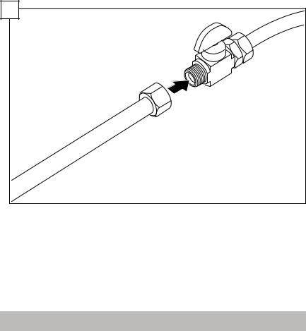
23 |
Connect the dishwasher water supply line to the water shut off valve.
You will need to use an approved dishwasher water supply line with the correct fittings for this connection. Always use the appropriate seal when making plumbing connections.
After all connections are made, turn on the hot water and check for leaks.
Drain Connections
IMPORTANT NOTES about your drain connection:
•If local ordinance require an air gap, install it according to the manufacturer’s instructions.
•If the dishwasher drain hose is to be connected to a disposer dishwasherdrainconnection,removetheplugfromthedisposer’s dishwasher drain connection.
•The dishwasher drain hose must have one place along its length that is securely attached 20″ (508mm) above the cabinet floor.
•The drain hose length can be extended if necessary. The maximum length of the drain hose, including the hose leading to the air gap, is
150″ (3800mm).
22
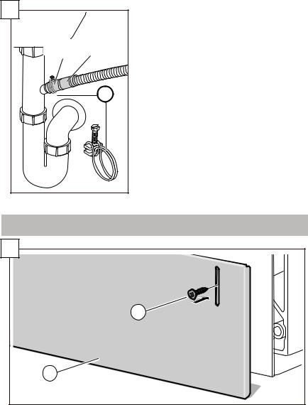
24
screws not provided


You may use the piece you removed in Step 7 to attach to the inside of the cabinet and hang the drain hose from as shown (screws are not supplied) in place of using a Nonmetallic Tie as pictured in the next illustrations. Do not exceed 43” in drain hose height.
The dishwasher drain hose must be installed with a portion of it at least
20” (508mm) off the cabinet floor; otherwise the dishwasher may not drain properly.
23

NOTE: Place hose clamp around end of drain hose BEFORE connecting to the plumbing.
25 |
a |
C |
b |
C |
|
|
The dishwasher drain hose may be connected to the drain plumbing using an air gap in one of two ways:
-Connect to the under sink dishwasher drain connection (25a).
-Connect to a disposer dishwasher drain connection (25b).
|
c |
|
|
C |
|
|
|
|
|
d |
|
|
|
|
C |
|
|
|
|
|||
|
|
||
The dishwasher drain hose may be connected to the drain plumbing using a high loop in one of two ways:
- Connect to the under sink dishwasher drain connection (25c).
24 - Connect to a disposer dishwasher drain connection (25d).
26 |
|
|
|
|
|
|
|
|
C |
Use the clamp provided (C) to attach the drain hose to the house plumbing as shown.
Attaching the Toe Panel
27 |
H |
G |
Position the slotted toe panel (G) on the dishwasher. Allow it to rest on the floor.
Attach using screws (H) as shown. Use only the supplied screws to avoid damaging the dishwasher. The toe panel should be flush with the floor. Your installation is complete!
25
 Loading...