


LTC 8540/00 Series
Instruction Manual
EN Alarm Interface Units
Instructions d’installation
FR Alarm Interface Units
Installationsanleitungen
DE Alarm Interface Units
Instrucciones de instalación
ES Alarm Interface Units
Installatie-instructies
NL Alarm Interface Units
Istruzioni per l’installazione
IT Alarm Interface Units

LTC 8540/00 Series | Instruction Manual | Contents |
EN | 2 |
|
|
EN |
Installation Instructions . . . . . . . . . . . . . . . . . . . . . . . . . . . . . . . . . . . . . . . . . . . . . . . . . . . . . . . . . . . . |
.2 |
FR |
Manuel d’utilisation . . . . . . . . . . . . . . . . . . . . . . . . . . . . . . . . . . . . . . . . . . . . . . . . . . . . . . . . . . . . . . . |
12 |
DE |
Installationshinweise . . . . . . . . . . . . . . . . . . . . . . . . . . . . . . . . . . . . . . . . . . . . . . . . . . . . . . . . . . . . . . . |
22 |
ES |
Instrucciones para la instalación . . . . . . . . . . . . . . . . . . . . . . . . . . . . . . . . . . . . . . . . . . . . . . . . . . . . . . |
30 |
NL |
Bedieningsvoorschrift . . . . . . . . . . . . . . . . . . . . . . . . . . . . . . . . . . . . . . . . . . . . . . . . . . . . . . . . . . . . . . |
38 |
IT |
Istruzioni per l’installazione . . . . . . . . . . . . . . . . . . . . . . . . . . . . . . . . . . . . . . . . . . . . . . . . . . . . . . . . . |
46 |
Bosch Security Systems | December 13, 2007

LTC 8540/00 Series | Instruction Manual | Important Safegaurds |
EN | 3 |
|
|
Important Safeguards
1.Read, Follow, and Retain Instructions - All safety and operating instructions should be read and followed before operating the unit. Retain instructions for future reference.
2.Heed Warnings - Adhere to all warnings on the unit and in the operating instructions.
3.Attachments - Attachments not recommended by the product manufacturer should not be used, as they may cause hazards.
4.Installation Cautions - Do not place this unit on an unstable stand, tripod, bracket, or mount. The unit may fall, causing serious injury to a person and serious damage to the unit. Use only manufacturerrecommended accessories, or those sold with the product. Mount the unit per the manufacturer's instructions. Appliance and cart combination should be moved with care. Quick stops, excessive force, or uneven surfaces may cause the appliance and cart combination to overturn.
5.Cleaning - Unplug the unit from the outlet before cleaning. Follow any instructions provided with the unit. Generally, using a damp cloth for cleaning is sufficient. Do not use liquid cleaners or aerosol cleaners.
6.Servicing - Do not attempt to service this unit yourself. Opening or removing covers may expose you to dangerous voltage or other hazards. Refer all servicing to qualified service personnel.
7.Damage Requiring Service - Unplug the unit from the main AC power source and refer servicing to qualified service personnel under the following conditions:
•When the power supply cord or plug is damaged.
•If liquid has been spilled or an object has fallen into the unit.
•If the unit has been exposed to water and/or inclement weather (rain, snow, etc.).
•If the unit does not operate normally, when following the operating instructions. Adjust only those controls specified in the operating instructions. Improper adjustment of other controls may result in damage, and require extensive work by a qualified technician to restore the unit to normal operation.
•If the unit has been dropped or the cabinet damaged.
•If the unit exhibits a distinct change in performance, this indicates that service is needed.
8.Replacement Parts - When replacement parts are required, the service technician should use replacement parts specified by the manufacturer or that have the same characteristics as the original part. Unauthorized substitutions may result in fire, electrical shock or other hazards.
9.Safety Check - Upon completion of servicing or repairs to the unit, ask the service technician to perform safety checks to ensure proper operating condition.
10.Power Sources - Operate the unit only from the type of power source indicated on the label. If unsure of the type of power supply to use, contact your dealer or local power company.
•For units intended to operate from battery power, refer to the operating instructions.
•For units intended to operate with External Power Supplies, use only the recommended approved power supplies.
•For units intended to operate with a limited power source, this power source must comply with EN60950. Substitutions may damage the unit or cause fire or shock.
•For units intended to operate at 24VAC, normal input voltage is 24 VAC. Voltage applied to the unit's power input should not exceed 30VAC. Usersupplied wiring, from the 24VAC supply to unit, must be in compliance with electrical codes (Class 2 power levels). Do not ground the 24VAC supply at the terminals or at the unit's power supply terminals.
11.Coax Grounding - If an outside cable system is connected to the unit, ensure that the cable system is grounded. U.S.A. models only - Section 810 of the National Electrical Code, ANSI/NFPA No.70, provides information regarding proper grounding of the mount and supporting structure, grounding of the coax to a discharge unit, size of grounding conductors, location of discharge unit, connection to grounding electrodes, and requirements for the grounding electrode.
12.Grounding or Polarization - This unit may be equipped with a polarized alternating current line plug (a plug with one blade wider than the other). This safety feature allows the plug to fit into the power outlet in only one way. If unable to insert the plug fully into the outlet, try reversing the plug. If the plug still fails to fit, contact an electrician to arrange replacement of the obsolete outlet. Do not defeat the safety purpose of the polarized plug.
Alternately, this unit may be equipped with a 3-wire grounding plug (a plug with a third pin, for grounding). This safety feature allows the plug to fit
into a grounding power outlet only. If unable to insert the plug into the outlet, contact an electrician to arrange replacement of the obsolete outlet. Do not defeat the safety purpose of the grounding plug.
13.Lightning - For added protection during a lightning storm, or when this unit is left unattended and unused for long periods of time, unplug the unit from the wall outlet and disconnect the cable system. This will prevent damage to the unit due to lightning and power line surges.
Bosch Security Systems | December 13, 2007
LTC 8540/00 Series | Instruction Manual | Safety Precautions |
EN | 4 |
|
|
For Indoor Product
1.Water and Moisture - Do not use this unit near water - for example, in a wet basement, in an unprotected outdoor installation or in any area classified as a wet location.
2.Object and Liquid Entry - Never push objects of any kind into this unit through openings, as they may touch dangerous voltage points or short out parts that could result in a fire or electrical shock. Never spill liquid of any kind on the unit.
3.Power Cord and Power Cord Protection - For units intended to operate with 230VAC, 50Hz, the input and output power cord must comply with the latest versions of IEC Publication 227 or IEC Publication 245.
Power supply cords should be routed so they are not likely to be walked on or pinched. Pay particular attention to location of cords and plugs, convenience receptacles, and the point of exit from the appliance.
4.Overloading - Do not overload outlets and extension cords; this can result in a risk of fire or electrical shock.
For Outdoor Product
Power Lines - An outdoor system should not be located in the vicinity of overhead power lines, electric lights or power circuits, or where it may contact such power lines or circuits. When installing an outdoor system, extreme care should be taken to keep from touching power lines or circuits, as this contact might be fatal. U.S.A. models only - refer to the National Electrical Code Article 820 regarding installation of CATV systems.
For Rack-mount Product
1.Ventilation - This unit should not be placed in a built-in installation or rack, unless proper ventilation is provided, or the manufacturer’s instructions have been adhered to. The equipment must not exceed its maximum operating temperature requirements.
2.Mechanical Loading - Mounting of the equipment in a rack shall be such that a hazardous condition is not achieved due to uneven mechanical loading.
|
|
WARNING: |
|
|
Electrostatic-sensitive device. Use |
|
|
proper CMOS/MOSFET handling |
|
ATTENTION |
precautions to avoid electrostatic |
|
OBSERVE PRECAUTIONS |
discharge. |
|
FOR HANDLING |
|
|
ELECTROSTATIC SENSITIVE |
|
|
DEVICES |
|
|
|
|
NOTE: Grounded wrist straps must be worn and proper ESD safety precautions observed when handling the electrostaticsensitive printed circuit boards.
Safety Precautions
CAUTION: TO REDUCE THE RISK OF
ELECTRIC SHOCK, DO NOT REMOVE COVER (OR BACK). NO USER SERVICEABLE PARTS INSIDE. REFER SERVICING TO QUALIFIED SERVICE PERSONNEL.
This symbol indicates the presence of uninsulated “dangerous voltage” within the product’s enclosure. This may constitute a risk of electric shock.
The user should consult the operating and maintenance (servicing) instructions in the literature accompanying the appliance.
Attention: Installation should be performed by qualified service personnel only in accordance with the National Electrical Code or applicable local codes.
Power Disconnect. Units with or without ON-OFF switches have power supplied to the unit whenever the power cord is inserted into the power source; however, the unit is operational only when the ON-OFF switch is in the ON position. The power cord is the main power disconnect for all units.
Bosch Security Systems | December 13, 2007

LTC 8540/00 Series | Instruction Manual | FCC & ICES Information |
EN | 5 |
|
|
FCC & ICES INFORMATION
(U.S.A. and Canadian Models Only)
This device complies with part 15 of the FCC Rules. Operation is subject to the following two conditions:
(1)This device may not cause harmful interference, and
(2)This device must accept any interference received, including interference that may cause undesired operation.
NOTE: This equipment has been tested and found to comply with the limits for a Class B digital device, pursuant to Part 15 of the FCC Rules and ICES-003 of Industry Canada. These limits are designed to provide reasonable protection against harmful interference when the equipment is operated in a residential installation. This equipment generates, uses and can radiate radio frequency energy, and if not installed and used in accordance with the instructions, may cause harmful interference to radio communications. However, there is no guarantee that interference will not occur in a particular installation. If this equipment does cause harmful interference to radio or television reception, which can be determined by turning the equipment off and on, the user is encouraged to try to correct the interference by one or
more of the following measures:
•Reorient or relocate the receiving antenna.
•Increase the separation between the equipment and receiver.
•Connect the equipment into an outlet on a circuit different from that to which the receiver is connected.
•Consult the dealer, or an experienced radio/TV technician for help.
Intentional or unintentional changes or modifications, not expressly approved by the party responsible for compliance, shall not be made. Any such changes or modifications could void the user’s authority to operate the equipment.The user may find the following booklet, prepared by the Federal Communications Commission, helpful: How to Identify and Resolve Radio-TV Interference Problems. This booklet is available from the U.S. Government Printing Office, Washington, DC 20402, Stock No. 004-000-00345-4.
Bosch Security Systems | December 13, 2007

LTC 8540/00 Series | Instruction Manual | Table of Contents |
EN | 6 |
|
|
Table of Contents |
|
|
Important Safeguards . . . . . . . . . . . . . . . . . . . . . . . . . . . . . . . . . . . . . . . . . . . . . . . . . . . . . . . . . . . . . . . . . . . |
.3 |
|
FCC Information . . . . . . . . . . . . . . . . . . . . . . . . . . . . . . . . . . . . . . . . . . . . . . . . . . . . . . . . . . . . . . . . . . . . . . |
.5 |
|
1 |
UNPACKING . . . . . . . . . . . . . . . . . . . . . . . . . . . . . . . . . . . . . . . . . . . . . . . . . . . . . . . . . . . . . . . . . . . |
.7 |
2 |
SERVICE . . . . . . . . . . . . . . . . . . . . . . . . . . . . . . . . . . . . . . . . . . . . . . . . . . . . . . . . . . . . . . . . . . . . . . |
.7 |
|
DESCRIPTION . . . . . . . . . . . . . . . . . . . . . . . . . . . . . . . . . . . . . . . . . . . . . . . . . . . . . . . . . . . . . . . . . |
.7 |
4 |
INSTALLATION . . . . . . . . . . . . . . . . . . . . . . . . . . . . . . . . . . . . . . . . . . . . . . . . . . . . . . . . . . . . . . . . |
.7 |
4.1 |
Power/Data . . . . . . . . . . . . . . . . . . . . . . . . . . . . . . . . . . . . . . . . . . . . . . . . . . . . . . . . . . . . . . . . . . . . . |
.7 |
4.2 |
Mounting Options . . . . . . . . . . . . . . . . . . . . . . . . . . . . . . . . . . . . . . . . . . . . . . . . . . . . . . . . . . . . . . . . |
.7 |
4.3 |
Allegiant CPU Bay Connections . . . . . . . . . . . . . . . . . . . . . . . . . . . . . . . . . . . . . . . . . . . . . . . . . . . . . |
.8 |
4.4 |
Operational Settings . . . . . . . . . . . . . . . . . . . . . . . . . . . . . . . . . . . . . . . . . . . . . . . . . . . . . . . . . . . . . . |
.8 |
4.5 |
Alarm Input Connections . . . . . . . . . . . . . . . . . . . . . . . . . . . . . . . . . . . . . . . . . . . . . . . . . . . . . . . . . . |
.9 |
4.6 |
Alarm Output Connections . . . . . . . . . . . . . . . . . . . . . . . . . . . . . . . . . . . . . . . . . . . . . . . . . . . . . . . . . |
.9 |
4.7 |
Interface Port Pinouts . . . . . . . . . . . . . . . . . . . . . . . . . . . . . . . . . . . . . . . . . . . . . . . . . . . . . . . . . . . . . |
10 |
5 |
ILLUSTRATIONS . . . . . . . . . . . . . . . . . . . . . . . . . . . . . . . . . . . . . . . . . . . . . . . . . . . . . . . . . . . . . . . |
11 |
Bosch Security Systems | December 13, 2007

LTC 8540/00 Series | Instruction Manual | Unpacking |
EN | 7 |
|
|
1UNPACKING
Unpack carefully. This is electronic equipment and should be handled with care.
Check for the following items:
•Verify the model number of the unit
•One (1) cable with 9-pin D-sub connectors
•Connector Kit, containing ten (10) pieces of a twelve (12) pin connector
•Installation manual
If an item appears to have been damaged in shipment, replace it properly in its carton and notify the shipper. If any items are missing, notify your Bosch Security Systems Sales Representative or Customer Service.
The shipping carton is the safest container in which the unit may be transported. Save it for possible future use.
2SERVICE
If the unit ever needs repair service, the customer should contact the nearest Bosch Security Systems, Inc. Service Center for return authorization and shipping instructions.
Service Centers
USA
Telephone: 800-366-2283 or 585-340-4162 Fax: 800-366-1329
Email: cctv.repair@us.bosch.com
Customer Service
Telephone: 800-289-0096 Fax: 585-223-9180
Email: security.sales@us.bosch.com
Technical Support
Telephone: 800-289-0096
Fax: 585-223-3508 or 717-735-6560 Email: technical.support@us.bosch.com
Repair Center
Telephone: 585-421-4220
Fax: 585-223-9180 or 717-735-6561 Email: security.repair@us.bosch.com
Canada
Telephone: 514-738-2434 Fax: 514-738-8480
Europe, Middle East & Asia Pacific Region
Telephone: 44 (0) 1495 274558 Fax: 44 (0) 1495 274280
Email: rmahelpdesk@solectron.com
3DESCRIPTION
The LTC 8540/00 Alarm Interface Unit provides the Allegiant® series of matrix switcher/controllers (LTC 8500, LTC 8600, TC8700, and LTC 8800) with
the ability to automatically display video under alarm conditions. The LTC 8540/00 accepts up to 64 contact closures or logic level inputs from remote sensing devices such as door contacts, PIRs, etc., and then reports the “alarm” information to the Allegiant series main CPU bay. Alarm inputs may be configured in groups of 32 to accept either normally open or normally closed contacts. The LTC 8540/00 also provides eight relay closure outputs upon alarm conditions
4INSTALLATION
4.1Power/Data
An interface cable for data/power between the LTC 8540/00 unit and the Allegiant CPU bay is supplied. If required, the Alarm Interface Unit may
also be installed remotely using a user supplied Listed Class 2 or equivalent 12 VAC or 12 VDC, 8 W power source. A minimal 3 or 5 wire RS-232 interface would then be required for communication to the Allegiant CPU bay. If necessary, the supplied cable can be cut and spliced to make the appropriate connections. A table listing the unit’s interface port pinouts can be found at the end of this manual. Allegiant port pinouts are listed in the QUICK REFERENCE MAIN BAY REAR PANEL CONNECTOR PINOUTS section of the Allegiant Series Installation and Operating Instructions.
Caution: DO NOT connect an external voltage source to this unit if it is already connected directly to the Allegiant CPU bay using the supplied cable.
4.2Mounting Options
4.2.1 Rack Mount
The LTC 8540/00 unit is supplied from the factory in an enclosure suitable for rack mounting. The enclosure is one EIA standard rack width by two rack heights. Peel off the four rubber feet located on the bottom of the enclosure before installing into console.
Bosch Security Systems | December 13, 2007
LTC 8540/00 Series | Instruction Manual | Installation
4.2.2 Desk Top Mount
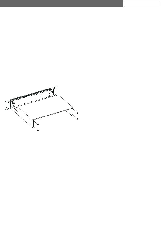
If the unit is not going to be rack mounted, the enclosure’s mounting ears should be removed. The cover of the unit must be removed before access to the mounting ears is possible. Removal of the cover should only be performed by qualified service personnel. The unit should always be disconnected from the Allegiant CPU bay (or alternate power source if one is being used) before removing the cover.
The top cover is fastened to the case by 4 screws located on the rear of the unit. Once the screws have been removed, the cover slides back and off the unit. Remove each mounting ear by removing the screw holding the mounting ear to the enclosure chassis. Refer to the drawing below if needed.
Cover and Rack Ears Removal
4.3Allegiant CPU Bay Connections
With the power turned “OFF” on the Allegiant series main CPU bay, install the alarm interface unit in the rack close enough to the location of the main CPU bay to allow the supplied cable to be used.
Connect one end of the supplied 9-pin D-type cable labeled “ALARM” to the rear of the unit and the other end to the Allegiant main CPU bay connector marked “ALARM”. Remember to tighten both connector attachment screws at each connection point. The front panel LED should light upon application of power to the main CPU bay.
EN | 8
4.4Operational Settings
The unit contains internal DIP switches which can be used to set certain operating characteristics. The lid to the unit must be removed as described above if the DIP switches need to be changed from their Factory default settings. Refer to the LTC 8540/00 table below for DIP locations. The following tables summarize the DIP switch settings and their associated features:
LTC 8540/00
S103 - DIP |
Function |
Switch No. |
|
1 |
ON for alarms 1 to 32 as normally open (NO).1 |
|
OFF for alarms 1 to 32 as normally closed (NC). |
2 |
ON for alarms 33 to 64 as normally open (NO).1 |
|
OFF for alarms 33 to 64 as normally closed (NC). |
3 |
ON for alarm output relays as normally open (NO).1 |
|
OFF for alarm output relays as normally closed |
|
(NC). |
4 |
ON for audible buzzer enabled.1 |
|
OFF to disable audible buzzer. |
|
|
|
|
S101 - DIP |
|
Switch No. |
Function |
4 |
ON for RTS/CTS enabled. |
|
OFF to disable RTS/CTS.1 |
|
|
1Denotes Factory default settings.
The unit communicates with the Allegiant main CPU bay using RS-232. The first three switches of DIP switch S101 are used to select the desired baud rate. Refer to the LTC 8540/00 layout diagram below for locations. Follow the table if a change from the Factory default setting is required.
Note that the Allegiant CPU bay must also be set to the same baud rate.
LTC 8540/00
S101 - DIP Switch No. |
|
Baud |
|
1 |
2 |
3 |
Rate |
OFF |
OFF |
OFF |
192001 |
OFF |
OFF |
ON |
9600 |
OFF |
ON |
OFF |
4800 |
OFF |
ON |
ON |
2400 |
ON |
OFF |
OFF |
12002 |
ON |
OFF |
ON |
600 |
ON |
ON |
OFF |
Not Used |
ON |
ON |
ON |
Not Used |
|
|
|
|
1Denotes Factory default settings on units starting with serial No. 1500.
2Denotes Factory default settings on units below serial No. 1500.
Bosch Security Systems | December 13, 2007

LTC 8540/00 Series | Instruction Manual | Installation
4.5Alarm Input Connections
Connect any 2 conductor wire (shielded cable not usually required) between the alarming device (contact closure or logic level, 0 to 5 VDC) and the appropriate LTC 8540/00 input. The alarm input numbers are marked on the rear panel. Note that two alarm inputs share a common ground connection. The alarm inputs can be configured in groups of 32 to accept either normally open (Factory default) or normally closed type contacts. Refer to the operational settings information above if changes from the Factory default settings are necessary. The total wire ‘loop resistance’ should not exceed 1000 ohms. The unit’s input #1 corresponds to camera #1 in the Factory default setting, but this relationship can be changed during programming with the optional Allegiant Master Control Software package.
4.6Alarm Output Connections
The LTC 8540/00 unit provides eight alarm relay outputs. An alarm output is typically used to activate the alarm input of a security type VCR or other alerting device. A VCR is normally programmed to change recording speeds from a slower time lapse mode to a faster real time mode upon alarm activation.
Operation of the eight relay outputs of the
LTC 8540/00 depends upon how the Allegiant system has been configured to respond to alarm events. The alarm output relays activate accordingly under the following conditions:
1.Relay 1 will activate if the base Allegiant system is set to use the Basic alarm response mode and an alarm occurs on any system monitor. Relay 1 will deactivate after all alarms have been removed from the inputs. Relay 1 will also deactivate if the Allegiant system is disarmed (either the monitor being disarmed or the alarm(s) being disarmed) by an operator from the keyboard. Pressing the Acknowledge key on the system keyboard will not deactivate Relay 1 since the alarm video follows the contact applied to the unit in this alarm response mode. Relays 2 through 8 are not used in this mode.
EN | 9
2.Relay 1 will activate if the base Allegiant system is set to use the Sequence & Display alarm response mode and an alarm occurs on any system monitor. Relay 1 will deactivate after all alarm videos have been acknowledged (pressing the keyboard Acknowledge key) by the system operator(s) from all system monitors. Relay 1 will also deactivate if the Allegiant system is disarmed (either the monitor being disarmed or the alarm(s) being disarmed) by an operator from the keyboard. Removal of the alarm input will not deactivate Relay 1 since the alarm video(s) are not dependent upon the duration of the contact applied to the unit in this alarm response mode. Relays 2 through 8 are not used in this mode.
3.If the base Allegiant system is set to use the Autobuild alarm response mode and an alarm occurs on system monitors 1 through 8, the relay corresponding to the monitor number will activate for the duration that the corresponding alarm input is applied to the unit. The relay will deactivate if the monitor associated with the relay or if the alarm(s) being displayed on the monitor is disarmed by an operator from the keyboard. Pressing the Acknowledge key on the system keyboard will not deactivate the relays since the alarm video follows the contact applied to the unit in this alarm response mode.
4.If the VersAlarm™ Group Table screen in the PC based Master Control Software package contains an alarm group where Monitors 1 through 8 are included and the ‘Monitor’ option has been selected in the ‘Relay Action’ column, the relay corresponding to the monitor number will activate for the duration that the alarm video remains on the monitor. The relay will deactivate if the monitor associated with the relay or if the alarm(s) being displayed on the monitor is disarmed by an operator from the keyboard. Pressing the Acknowledge key on the system keyboard will not deactivate the relay unless this feature has been selected for the associated alarm group. If the ‘Monitor’ option has been set to ‘1’ in the Group Table, only Relay 1 will activate when monitors in that alarm group become alarmed.
Bosch Security Systems | December 13, 2007

LTC 8540/00 Series | Instruction Manual | Installation |
EN | 10 |
|
|
Typically any 2 conductor wire can be used between the rear panel terminal block containing the unit relay outputs and the VCR alarm input. If some other external device is to be controlled, do not exceed the relay ratings of 10 W, 0.75 A.
4.7Interface Port Pinouts
Follow the table below if a cable other than the one supplied with the LTC 8540/00 will be used.
9-Pin |
Function |
1 |
Chassis Ground |
2 |
Receive |
3 |
Transmit |
4 |
CTS |
5 |
RTS |
6 |
Data Ground |
7 |
Data Ground |
8 |
12 VAC in or 12 VDC in |
9 |
12 VAC in or 12 VDC in |
|
|
Bosch Security Systems | December 13, 2007

LTC 8540/00 Series | Instruction Manual | Illustrations |
EN | 11 |
|
|
5ILLUSTRATIONS
OFF |
ON |
S103 |
4 3 2 1 |
S101 |
4 3 2 1 |
DIP SWITCH
LTC 8540/00 Alarm Interface Unit Layout
ALARM
POWER
|
|
|
|
|
|
Front |
|
|
|
|
A8 |
A16 |
A24 |
A32 |
A40 |
A48 |
A56 |
A64 |
R6 |
12 V |
RS232 |
|
||||||||||
GND |
GND |
GND |
GND |
GND |
GND |
GND |
GND |
R6 |
12 V |
|
A7 |
A15 |
A23 |
A31 |
A38 |
A47 |
A55 |
A63 |
R5 |
|
|
A6 |
A14 |
A22 |
A30 |
A38 |
A46 |
A54 |
A62 |
R5 |
|
|
GND |
GND |
GND |
GND |
GND |
GND |
GND |
GND |
R4 |
|
|
A5 |
A13 |
A21 |
A29 |
A37 |
A45 |
A53 |
A61 |
R4 |
|
|
A4 |
A12 |
A20 |
A28 |
A36 |
A44 |
A52 |
A60 |
R3 |
|
|
GND |
GND |
GND |
GND |
GND |
GND |
GND |
GND |
R3 |
|
|
A3 |
A11 |
A19 |
A27 |
A35 |
A43 |
A51 |
A59 |
R2 |
R8 |
|
A2 |
A10 |
A18 |
A26 |
A34 |
A42 |
A50 |
A58 |
R2 |
R8 |
|
GND |
GND |
GND |
GND |
GND |
GND |
GND |
GND |
R1 |
R7 |
|
A1 |
A9 |
A17 |
A25 |
A33 |
A41 |
A49 |
A57 |
R1 |
R7 |
|
|
|
|
|
|
|
Rear |
|
|
|
|
LTC 8540/00 Front and Rear Panel
Typical LTC 8540/00 Alarm Interface Application
System Monitor
001 |
ALM |
12:00:00 |
MAIN LOBBY DOOR 11 11 90 |
||
|
|
LTC 8540/00 Alarm |
Door Alarm |
|
Flashing On-Screen |
|
Contact |
||
|
Interface Unit |
|
||
Alarm Indicator |
|
|
|
|
|
|
Alarm |
RS-232 |
|
|
|
Output |
Alarm |
|
VCR |
|
Relay |
Data |
|
|
|
|
Typical |
|
Alarm Input |
|
|
|
|
|
|
System |
VIDEO CASSETTE RECORDER |
Allegiant Series |
Cameras |
|
||
|
Switcher/Controller |
|
|
Main CPU Equipment Bay |
|
Security VCR
S9405014AE
System Keyboard
Bosch Security Systems | December 13, 2007

LTC 8540/00 Série | Instructions d’installation | Consignes de Sécurité Importants |
FR | 12 |
|
|
Consignes de Sécurité Importantes
1.Lisez, observez et conservez les instructions ci après - Lisez et observez scrupuleusement
l'ensemble des instructions de sécurité et d'utilisation avant d'employer l'appareil, et conservez-les pour référence ultérieure.
2.Respectez les avertissements - Respectez les différents avertissements repris sur l'appareil et dans les instructions d'utilisation.
3.Fixations - Utilisez exclusivement les fixations recommandées par le fabricant, au risque d'exposer les utilisateurs à des situations potentiellement dangereuses.
4.Mises en garde relatives à l'installation - Évitez de placer l'appareil sur un pied, un trépied, un support ou une monture instable. L'appareil risque de tomber, de provoquer des lésions corporelles graves et de subir des dégâts importants. Utilisez exclusivement les accessoires recommandés par le fabricant ou fournis avec l'appareil. Installez l'appareil conformément aux instructions du fabricant. Si vous utilisez un chariot pour déplacer l'appareil, manipulez le chariot avec précaution. Les arrêts brusques, les forces excessives et les surfaces inégales risquent d'entraîner le renversement du chariot et de l'appareil.
5.Nettoyage - Avant de nettoyer l'appareil, débranchezle de la prise de courant. Observez les instructions fournies avec l'appareil. En règle générale, l'utilisation d'un chiffon humide suffit pour nettoyer l'appareil. Évitez l'emploi de nettoyants liquides ou aérosol.
6.Réparation - N'essayez pas de réparer vous-même l'appareil : l'ouverture et le retrait des capots présente un risque d'électrocution et d'autres dangers. Confiez la réparation de l'appareil à du personnel qualifié.
7.Dégâts nécessitant réparation - Débranchez l'appareil de la prise de courant et confiez la réparation
àdu personnel qualifié dans les cas suivants :
•Détérioration du cordon ou de la fiche d’alimentation ;
•Infiltration de liquide ou introduction d'objets dans l'appareil ;
•Exposition de l'appareil à l'eau ou aux intempéries (pluie, neige, etc.) ;
•Fonctionnement anormal de l'appareil, malgré l'observation des instructions d'utilisation. Procédez uniquement au réglage des commandes tel qu'indiqué dans les instructions d'utilisation. Tout autre réglage risque d'endommager l'appareil et implique généralement d'importants travaux de réparation par un technicien qualifié ;
•Chute de l'appareil ou dégâts au niveau du boîtier ;
•Constatation d'une modification au niveau des performances de l'appareil.
8.Pièces de rechange - En cas de remplacement de pièces, veillez à ce que le technicien utilise des pièces recommandées par le fabricant ou des pièces présentant les mêmes caractéristiques que les pièces d'origine. L'utilisation de pièces non homologuées présente un risque d'incendie, d'électrocution et d'autres dangers.
9.Contrôle de sécurité - Une fois les travaux d'entretien ou de réparation terminés, demandez au technicien de procéder à un contrôle de sécurité pour vérifier si l'appareil est en parfait état de marche.
10.Alimentation - Utilisez exclusivement le type d'alimentation indiqué sur l'étiquette. En cas de doute sur le type d'alimentation à utiliser, consultez votre revendeur ou votre fournisseur d'électricité local.
•Pour les modèles nécessitant une pile, reportez-vous aux instructions d'utilisation.
•Pour les modèles nécessitant une alimentation externe, utilisez exclusivement les sources d'alimentation homologuées recommandées.
•Pour les modèles nécessitant une source d'alimentation limitée, utilisez une source d'alimentation conforme à la norme EN60950. L'utilisation d'autres types de source d'alimentation risque d'endommager l'appareil, voire de provoquer un incendie ou une électrocution.
•Pour les modèles nécessitant une alimentation 24 Vca, utilisez une tension d'entrée standard de 24 Vca. La tension appliquée à l'entrée d'alimentation de l'appareil ne peut dépasser
30 Vca. Le câblage fourni par l'utilisateur,
de l'alimentation 24 Vca vers l'appareil, doit être conforme aux codes d'électricité en vigueur (niveaux de puissance de classe 2). L'alimentation 24 Vca des bornes et des bornes d'alimentation de l'appareil ne doit pas être mise à la terre.
11.Mise à la terre du câble coaxial - Si vous connectez un système de câblage externe à l'appareil, assurez-vous que ce système de câblage est mis à la terre. Modèles américains uniquement : la section 810 du code national d'électricité américain (NEC), ANSI/ NFPA n° 70, fournit des informations sur la mise à la terre de la monture et de la structure portante, la mise à la terre du câble coaxial vers un dispositif de décharge, la taille des conducteurs de terre, l'emplacement du dispositif de décharge, la connexion aux électrodes de terre et les exigences relatives aux électrodes de terre.
12.Mise à la terre ou polarisation - Cet appareil peut être équipé d'une fiche polarisée de courant alternatif (fiche présentant une broche plus large que l'autre). Grâce à ce dispositif de sécurité, la fiche ne s'insère dans la prise que dans un sens. Si la fiche n'entre pas complètement dans la prise, retournez la fiche. Si le problème persiste, demandez à un électricien de remplacer la prise. Ne retirez en aucun cas le dispositif de sécurité de la fiche polarisée.
Cet appareil peut également être équipé d'une fiche de terre 3 fils (fiche présentant une troisième broche, destinée à la mise à la terre). Grâce à ce dispositif de sécurité, la fiche ne s'insère que dans une prise de terre. Si la fiche n'entre pas dans la prise, demandez à un électricien de remplacer la prise. Ne retirez en aucun cas le dispositif de sécurité de la fiche de terre.
13.Orage - Pour davantage de protection en cas d'orage, ou si vous n'avez pas l'intention d'utiliser l'appareil pendant une période prolongée, débranchez l'appareil de la prise murale et déconnectez le système de câblage. Cette opération permet d'éviter les dégâts au niveau de l'appareil en cas d'orage ou de surtension des lignes électriques.
Bosch Security Systems | December 13, 2007
LTC 8540/00 Série | Instructions d’installation | Consignes de Sécurité Importa |
FR | 13 |
|
|
Modèle Destiné Aux Applications
D'intérieur
1.Eau et humidité - Évitez d'utiliser l'appareil à proximité d’un point d'eau, par exemple dans une cave humide, dans une installation d'extérieur non protégée ou à tout autre endroit exposé à l'humidité.
2.Infiltration de liquide ou introduction d'objets - N'introduisez aucun objet dans les orifices de l'appareil. Ces objets risquent d'entrer en contact avec des points de tension dangereuse, d'entraîner le court-circuit de certains composants et de provoquer un incendie ou une électrocution. Évitez de renverser des substances liquides sur l'appareil.
3.Cordon d'alimentation et protection du cordon d'alimentation - Pour les modèles nécessitant une alimentation 230 Vca, 50 Hz, utilisez un cordon d'alimentation d'entrée et de sortie conforme aux exigences imposées par la dernière version de la publication IEC 227 ou 245. Acheminez les cordons d'alimentation de sorte qu'ils ne soient ni piétinés ni comprimés. Portez une attention particulière à l'emplacement des cordons, des fiches, des prises de courant et du point de sortie de l'appareil.
4.Surcharge - Pour éviter tout risque d'incendie ou d'électrocution, ne surchargez pas les prises de courant ni les rallonges.
Modèle Destiné Aux Applications
D'extérieur
Lignes électriques - Évitez de placer les systèmes extérieurs à proximité de lignes électriques aériennes, de systèmes d'éclairage électrique, de circuits électriques, ou à un endroit où ils risquent d'entrer en contact avec de tels dispositifs. Lors de l'installation d'un système d'extérieur, évitez de toucher les lignes et les circuits électriques : un tel contact peut être fatal. Modèles américains uniquement : consultez l’article 820 du code national d’électricité américain (NEC) relatif à l’installation des systèmes de câblodistribution (CATV).
Modèle Destiné Au Montage En Bâti
1.Ventilation - Évitez de placer l'appareil dans un bâti ou dans une installation intégrée, sauf si la ventilation s'y effectue correctement ou si le fabricant préconise une telle disposition. La température de fonctionnement de l'appareil ne peut dépasser la valeur maximale indiquée.
2.Chargement mécanique - Le montage de l'appareil en bâti doit être exempt de tout risque d'accident lié à un chargement mécanique irrégulier.
|
|
|
|
AVERTISSEMENT : |
|
|
|
|
cet appareil est sensible aux décharges |
|
|
|
|
électrostatiques. Pour éviter tout risque |
|
|
ATTENTION |
|
de décharge électrostatique, observez |
|
|
Observez les précautions de |
|
les précautions de manipulation du |
|
|
manipulation des appareils |
|
|
|
|
sensibles aux décharges |
|
CMOS/MOSFET appropriées. |
|
|
électrostatiques. |
|
|
|
|
|
|
|
|
|
|
|
|
REMARQUE : lors de la manipulation des cartes à circuits imprimés sensibles aux décharges électrostatiques, portez des bracelets antistatiques mis à la terre et observez les consignes de sécurité relatives aux décharges électrostatiques.
Sécurité
Attention : l'installation doit exclusivement être réalisée par du
ATTENTION : POUR ÉVITER TOUT RISQUE D'ÉLECTROCUTION,
N'ESSAYEZ PAS DE RETIRER LE CAPOT (OU LE PANNEAU
ARRIÈRE). CET APPAREIL NE CONTIENT AUCUN COMPOSANT
SUSCEPTIBLE D'ÊTRE RÉPARÉ PAR L'UTILISATEUR. CONFIEZ
LA RÉPARATION DE L'APPAREIL À DU PERSONNEL QUALIFIÉ.
Ce symbole signale que le produit renferme une « tension potentiellement dangereuse » non isolée susceptible de provoquer une électrocution.
Ce symbole invite l'utilisateur à consulter les instructions d'utilisation et d'entretien (dépannage) reprises dans la documentation qui accompagne l'appareil.
personnel qualifié, conformément au code national d'électricité américain (NEC) ou au code d'électricité local en vigueur.
Coupure de l'alimentation. Qu'ils soient pourvus ou non d'un commutateur ON/OFF, tous les appareils reçoivent de l'énergie une fois le cordon branché sur la source d'alimentation. Toutefois, l'appareil ne fonctionne réellement que lorsque
le commutateur est réglé sur ON. Le débranchement du cordon d'alimentation permet de couper l'alimentation des appareils.
Bosch Security Systems | December 13, 2007

LTC 8540/00 Série | Instructions d’installation | Informations FCC et ICES |
FR | 14 |
|
|
INFORMATIONS FCC ET ICES
(modèles utilisés aux États-Unis et au Canada uniquement)
Cet appareil est conforme aux exigences imposées par la section 15 du règlement de la Commission fédérale des communications des États-Unis (FCC). Son utilisation est soumise aux deux conditions suivantes :
(1)Cet appareil ne doit pas provoquer d'interférences nuisibles, et
(2)doit supporter toutes les interférences reçues, dont les interférences susceptibles d'entraîner un fonctionnement imprévu.
REMARQUE : suite à différents tests, cet appareil s'est révélé conforme aux exigences imposées aux appareils numériques de classe B, en vertu de la section 15 du règlement de la Commission fédérale des communications des États-Unis (FCC), et en vertu de la norme ICES-003 d'Industrie Canada. Ces exigences visent à fournir une protection raisonnable contre les interférences nuisibles lorsque l'appareil est utilisé dans le cadre d'une installation résidentielle. Cet appareil génère, utilise et émet de l'énergie de radiofréquences et peut, en cas d'installation ou d'utilisation non conforme aux instructions, engendrer des interférences nuisibles au niveau des radiocommunications. Toutefois, rien ne garantit l'absence d'interférences dans une installation particulière. Il est possible de déterminer la production d'interférences en mettant l'appareil successivement hors et sous tension, tout en contrôlant la réception radio ou télévision. L'utilisateur peut parvenir à éliminer les interférences éventuelles en prenant une ou plusieurs des mesures suivantes :
•Modifier l'orientation ou l'emplacement de l'antenne réceptrice ;
•Éloigner l'appareil du récepteur ;
•Brancher l'appareil sur une prise située sur un circuit différent de celui du récepteur ;
•Consulter le revendeur ou un technicien qualifié en radio/télévision pour obtenir de l'aide.
Toute modification apportée au produit, non expressément approuvée par la partie responsable de l'appareil, est strictement interdite. Une telle modification est susceptible d'entraîner la révocation du droit d'utilisation de l'appareil.
La brochure suivante, publiée par la Commission fédérale des communications (FCC), peut s'avérer utile : « How to Identify and Resolve Radio-TV Interference Problems ». Cette brochure est disponible auprès du U.S. Government Printing Office, Washington, DC 20402, États-Unis, sous la référence
n° 004-000-00345-4.
Bosch Security Systems | December 13, 2007

LTC 8540/00 Série | Instructions d’installation | Sommaire |
FR | 15 |
|
|
SOMMAIRE
1 DEBALLAGE . . . . . . . . . . . . . . . . . . . . . . . . . . . . . . . . . . . . . . . . . . . . . . . . . . . . . . . . . . . . . . . . .16 2 SERVICE . . . . . . . . . . . . . . . . . . . . . . . . . . . . . . . . . . . . . . . . . . . . . . . . . . . . . . . . . . . . . . . . . . . .16 3 DESCRIPTION . . . . . . . . . . . . . . . . . . . . . . . . . . . . . . . . . . . . . . . . . . . . . . . . . . . . . . . . . . . . . . .16 4 INSTALLATION . . . . . . . . . . . . . . . . . . . . . . . . . . . . . . . . . . . . . . . . . . . . . . . . . . . . . . . . . . . . . .16 4.1 Alimentation/Données . . . . . . . . . . . . . . . . . . . . . . . . . . . . . . . . . . . . . . . . . . . . . . . . . . . . . . . . . .16 4.2 Options de montage . . . . . . . . . . . . . . . . . . . . . . . . . . . . . . . . . . . . . . . . . . . . . . . . . . . . . . . . . . . .17 4.3 Connexions de la baie du processeur central Allegiant . . . . . . . . . . . . . . . . . . . . . . . . . . . . . . . . . .17 4.4 Réglages opérationnels . . . . . . . . . . . . . . . . . . . . . . . . . . . . . . . . . . . . . . . . . . . . . . . . . . . . . . . . . . .17 4.5 Connexions d’entrée d’alarme . . . . . . . . . . . . . . . . . . . . . . . . . . . . . . . . . . . . . . . . . . . . . . . . . . . . .18 4.6 Connexions de sortie d’alarme . . . . . . . . . . . . . . . . . . . . . . . . . . . . . . . . . . . . . . . . . . . . . . . . . . . .18 4.7 Brochage du port d’interface . . . . . . . . . . . . . . . . . . . . . . . . . . . . . . . . . . . . . . . . . . . . . . . . . . . . . .19 5 ILLUSTRATIONS . . . . . . . . . . . . . . . . . . . . . . . . . . . . . . . . . . . . . . . . . . . . . . . . . . . . . . . . . . . . .20
Bosch Security Systems | December 13, 2007

LTC 8540/00 Série | Instructions d’installation | Deballage |
FR | 16 |
|
|
1DEBALLAGE
Veuillez procéder avec précaution lors du déballage. Ce matériel est de type électronique et il doit être manipulé avec soin.
Veuillez contrôler la présence des éléments suivants:
•Le numéro de modèle de l’appareil
•Un (1) cable avec un connecteur DB9
•Kit de connecteurs, contient 10 connecteurs 12 broches
•Manuel d'installation
Si un élément semble avoir été endommagé durant le transport, veuillez le remettre correctement dans son carton et en informer le transporteur. Si un ou plusieurs éléments sont manquants, veuillez en informer le représentant commercial ou le bureau d’assistance à la clientèle de Bosch Security Systems.
Le carton d’emballage d’origine constitue le meilleur moyen d’emballage pour le transport de l’appareil. Conservez-le à des fins d’utilisation ultérieure.
2SERVICE
Si l’appareil a besoin d’être réparé, le client est invité à contacter le Centre Technique de Bosch Security Systems, Inc.. le plus proche afin d’obtenir une autorisation de retour et des instructions d’expédition.
Centres d’entretien
États-Unis
Tél. : 800-366-2283 ou 585-340-4162 Fax : 800-366-1329
Email : cctv.repair@us.bosch.com
Assistance technique
Tél. : 800-326-1450
E-mail : technical.support@us.bosch.com
Pièces de rechange vidéosurveillance
Tél. : 800-894-5215 ou 408-957-3065 Fax : 408-935-5938
E-mail : BoschCCTVparts@ca.slr.com
Canada
Tél. : 514-738-2434
Fax : +514-738-8480
Europe, Moyen-Orient et région Asie-Pacifique
Tél. : 44 (0) 1495 274558
Fax : 44 (0) 1495 274280
E-mail : rmahelpdesk@solectron.com
Pour de plus amples informations, visitez le site www.boschsecurity.fr
3DESCRIPTION
Le module d’interface d’alarme LTC 8540/00 permet aux commutateurs/contrôleurs matriciels de la série Allegiant® (LTC 8500, LTC 8600, TC8700 et
LTC 8800) d’afficher automatiquement le signal vidéo lorsque des conditions d’alarme se produisent. Le LTC 8540/00 accepte jusqu’à 64 fermetures de contact ou entrées de niveau logique en provenance de
dispositifs de détection distants, comme des contacts de porte, des détecteurs passifs à infrarouge, etc., et il retransmet alors l’information d’alarme à la baie du processeur central de la série Allegiant. Les entrées d’alarme peuvent être configurées par groupes de 32 afin d’accepter des contacts soit normalement ouverts, soit normalement fermés. Le module LTC 8540/00 dispose également de huit sorties à fermeture de relais lorsque des conditions d’alarme se produisent.
4INSTALLATION
4.1Alimentation/Données
Il est fourni un câble d’interface pour alimentation et données afin de permettre le raccordement entre le module LTC 8540/00 et la baie du processeur central Allegiant. Le cas échéant, l'unité d'interface d'alarmes peut être installée à distance avec une alimentation 8 W, 12 Vca ou 12 Vcc, homologuée classe 2 ou équivalent, fournie par l'utilisateur. Une ligne d’interface RS-232 comportant au minimum 3 ou 5 fils est alors nécessaire pour assurer la communication avec la baie du processeur central Allegiant. Si nécessaire, le câble fourni peut être coupé et raccordé pour réaliser les connexions appropriées. Il est proposé à la fin de ce manuel une table indiquant le brochage du port d’interface du module. Le brochage du port Allegiant est indiqué dans la section TABLE DE RÉFÉRENCE RAPIDE DU BROCHAGE DES CONNECTEURS DU PANNEAU ARRIÈRE DE LA BAIE CENTRALE des Instructions d’installation et d’utilisation de la série Allegiant.
Attention: Ne raccordez jamais une alimentation électrique externe à ce module s’il est déjà connecté à la baie du processeur central Allegiant par l’intermédiaire du câble fourni.
Bosch Security Systems | December 13, 2007
LTC 8540/00 Série | Instructions d’installation | Installation |
FR | 17 |
|
|
4.2Options de montage
4.2.1 Montage en châssis
Le module LTC 8540/00 est livré d’usine dans un boîtier adapté au montage en châssis. Le boîtier est au format EIA, large d’une unité et haut de deux unités. Décollez les quatre pieds en caoutchouc se trouvant sous le boîtier avant de l’installer dans la console.
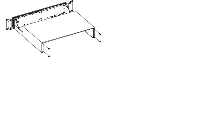
4.2.2 Montage sur dessus de bureau
Si le module n’est pas destiné à être installé en châssis, il est nécessaire d’en retirer les pattes de montage. Le couvercle de l’appareil doit être retiré afin de pouvoir accéder aux pattes de montage.Le retrait du couvercle ne doit être effectué que par un personnel technique qualifié. Le module doit toujours être déconnecté de la baie du processeur central Allegiant (ou de la source électrique externe, le cas échéant) avant de procéder au retrait du couvercle.
Le couvercle supérieur est fixé au boîtier par quatre vis situées à l’arrière de l’appareil. Après que les vis aient été retirées, il est possible de faire coulisser le couvercle vers l’arrière et de le dégager. Retirez chacune des pattes de fixation en retirant la vis maintenant la patte de fixation au châssis du boîtier. Si nécessaire, veuillez vous référer au schéma proposé ci-dessous.
4.3 Connexions de la baie du processeur central Allegiant
L’alimentation de la baie du processeur central Allegiant étant interrompue (“OFF”), installez le module d’interface d’alarme dans le châssis à proximité suffisante de l’emplacement de la baie du processeur central afin de permettre l’utilisation du câble fourni.
Raccordez une extrémité du câble de type D à 9 broches marqué “ALARM” à l’arrière du module et l’autre extrémité au connecteur de la baie du processeur central Allegiant marqué “ALARM”. Veillez à bien serrer les vis de fixation des connecteurs à chaque point de connexion. Le témoin LED du panneau avant doit s’allumer lorsque la baie du processeur central est mise sous tension.
4.4Réglages opérationnels
Le module contient des interrupteurs DIP internes qui peuvent être utilisés pour définir certaines caractéristiques opérationnelles. Le couvercle de l’appareil doit être retiré de la manière décrite ci-dessus si les réglages d’usine par défaut des interrupteurs DIP doivent être modifiés. Veuillez vous référer à la table LTC 8540/00 ci-dessous pour connaître la position des interrupteurs DIP. Les tables suivantes contiennent un récapitulatif des réglages des interrupteurs DIP et des fonctions qui leur sont associées:
Retrait du couvercle et des pattes pour châssis
Bosch Security Systems | December 13, 2007
 Loading...