

Bosch Power Tools GLL2-80 User Manual
IMPORTANT: IMPORTANT : IMPORTANTE:
G
LL
2
-80
P
P
r
o
fe
s
s
ion
a
l
Read Before Using Lire avant usage Leer antes de usar
Operating/Safety Instructions
Consignes de fonctionnement/sécurité
Instrucciones de funcionamiento y seguridad
GLL2-80
GLL 2-80
Call Toll Free for
Consumer Information
& Service Locations
1-877-BOSCH99 (1-877-267-2499) www.boschtools.com
Pour obtenir des informations
et les adresses de nos centres
de service après-vente,
appelez ce numéro gratuit
Llame gratis para
obtener información
para el consumidor y
ubicaciones de servicio
For English Version Version française Versión en español
See page 5 Voir page 13 Ver la página 22
G
LL
2-8
0
P
Pr
o
f
es
s
i
o
n
a
l
4
3
2
5
6
1
1
GLL 2-80
7
8
12
11
10
9
13
14
1
1
-2-
FE
D
C
BA
-3-
P
r
of
e
ss
io
nal
20
16
BP 350
17
19
LR 2
18
15
8
8
MW 1
HG
-4-

General Safety Rules
!
WARNING
serious injury. The term “tool” in all of the warnings listed below refers to your mains-operated
(corded) tool or battery-operated (cordless) tool.
!
WARNING
ALWAYS BE AWARE of their location when using the tool.
DO NOT remove or deface any warning or caution labels. Removing labels increases the risk
of exposure to laser radiation.
Use of controls or adjustments or performance of procedures other than those specified in this
manual, may result in hazardous radiation exposure.
ALWAYS make sure that any bystanders in the vicinity of use are made aware of the dangers
of looking directly into the laser tool.
DO NOT place the laser tool in a position that may cause anyone to stare into the laser beam
intentionally or unintentionally. Serious eye injury could result.
ALWAYS position the laser tool securely. Damage to the laser tool and/or serious injury to the
user could result if the laser tool fails.
ALWAYS use only the accessories that are recommended by the manufacturer of your laser
tool. Use of accessories that have been designed for use with other laser tools could result in
serious injury.
DO NOT use this laser tool for any purpose other than those outlined in this manual. This could
result in serious injury.
DO NOT leave the laser tool “ON” unattended in any operating mode.
DO NOT disassemble the laser tool. There are no user serviceable parts inside. Do not modify
the product in any way. Modifying the laser tool may result in hazardous laser
radiation exposure.
DO NOT use the laser viewing glasses as safety goggles. The laser viewing glasses are used
for improved visualization of the laser beam, but they do not protect against laser radiation.
DO NOT use the laser viewing glasses as sun glasses or in traffic. The laser viewing glasses
do not afford complete UV protection and reduce color perception.
DO NOT use any optical tools such as, but not limited to, telescopes or transits to view the
laser beam. Serious eye injury could result.
DO NOT stare directly at the laser beam or project the laser beam directly into the eyes of
others. Serious eye injury could result.
Read all instructions. Failure to follow all instructions listed below may
result in hazardous radiation exposure, electric shock, fire and/or
The following labels are on your laser tool for your convenience and
safety. They indicate where the laser light is emitted by the tool.
Do not direct the laser beam at persons or animals and do not stare into the
laser beam yourself. This tool produces laser class 2 laser radiation and
complies with 21 CFR 1040.10 and 1040.11 except for deviations pursuant to
Laser Notice No. 50, dated June 24, 2007. This can lead to persons
being blinded.
SAVE THESE INSTRUCTIONS
-5-

Work area safety
Keep work area clean and well lit.
Cluttered or dark areas invite accidents.
DO NOT operate the laser tool around
children or allow children to operate the
laser tool. Serious eye injury could result.
Electrical safety
!
WARNING
To reduce this risk, always follow all
instructions and warnings on the battery label
and package.
DO NOT short any battery terminals.
DO NOT charge alkaline batteries.
DO NOT mix old and new batteries. Replace
all of them at the same time with new
batteries of the same brand and type.
DO NOT mix battery chemistries.
Dispose of or recycle batteries per
local code.
DO NOT dispose of batteries in fire.
Keep batteries out of reach of children.
Remove batteries if the device will not be
used for several months.
Stay alert, watch what you are doing and
use common sense when operating a
tool. Do not use a tool while you are tired
or under the influence of drugs, alcohol
or medication. A moment of inattention
while operating a tool may result in serious
personal injury or incorrect
measurement results.
Use safety equipment. Always wear eye
protection. Safety equipment such as dust
mask, non-skid safety shoes, hard hat, or
hearing protection used for appropriate
conditions will reduce personal injuries.
Magnets
• Keep the tool and laser target plate 15
away from magnetic data medium and
magnetically-sensitive equipment. The
effect of the magnets of the tool and laser
target plate can lead to irreversible
data loss.
Batteries can explode or
leak, cause injury or fire.
Personal safety
Keep the tool and laser
target plate 15 away from
cardiac pacemakers. The
magnets of the tool and laser
target plate generate a field
that can impair the function of
cardiac pacemakers.
Noise Information
The A-weighted sound pressure level of the
audio signal at one meter distance is
80dB(A).
Do not hold the measuring tool close to
your ear!
Use and care
Use the correct tool for your application.
The correct tool will do the job better
and safer.
Do not use the tool if the switch does not
turn it on and off. Any tool that cannot be
controlled with the switch is dangerous and
must be repaired.
Store idle tool out of the reach of children
and do not allow persons unfamiliar with
the tool or these instructions to operate
the tool. Tools are dangerous in the hands
of untrained users.
Maintain tools. Check for misalignment or
binding of moving parts, breakage of
parts and any other condition that may
affect the operation. If damaged, tool
repaired before use. Many accidents are
caused by poorly maintained tools.
Use the tool, accessories, etc., in
accordance with these instructions and in
the manner intended for the particular
type of tool, taking into account the
working conditions and the work to be
performed. Use of the tool for operations
different from those intended could result in a
hazardous situation.
Service
Have your tool serviced by a qualified
repair person using only identical
replacement parts. This will ensure that the
safety of the tool is maintained.
Develop a periodic maintenance schedule
for tool. When cleaning a tool be careful
not to disassemble any portion of the tool
since internal wires may be misplaced or
pinched or may be improperly mounted.
Certain cleaning agents such as gasoline,
carbon tetrachloride, ammonia, etc. may
damage plastic parts.
SAVE THESE INSTRUCTIONS.
-6-

Intended Use
The tool is intended for determining and checking horizontal and vertical lines.
Preparation
Inserting/Replacing the Battery
Alkaline batteries are recommended for
the tool.
To open the battery compartment 12, slide
the latch 11 in the direction of the arrow and
fold the battery lid up. Insert the batteries.
When inserting, pay attention to the correct
polarity according to the representation on
the inside of the battery lid.
When the batteries become weak, a single 5
s audio signal will sound. The battery low
indicator 2 continuously flashes red. The tool
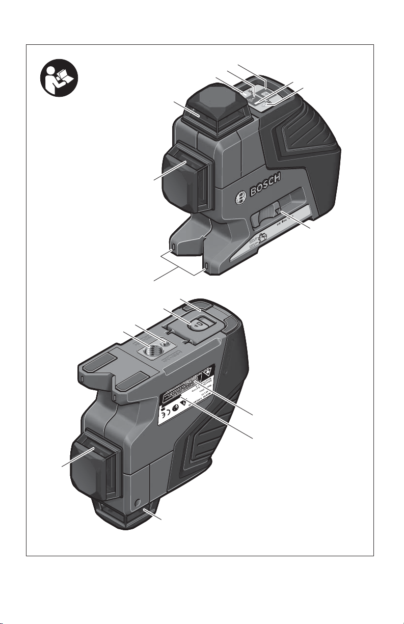
Features
The numbering of the product features shown
refers to the illustration of the tool on the
graphic page.
1 Exit opening for laser beam
2 Battery low indicator
3 Pulse-function button
4 Operating mode button
5 Pulse-function indicator
6 Working without automatic leveling
indicator
7 On/Off switch
8 Magnets
9 Tripod mount 5/8"
Technical Data
can be operated for less then 2 h.
When the batteries are weak when switching
on the tool, the 5 s audio signal will sound
directly after switching on the tool.
Always replace all batteries at the same time.
Only use batteries from one brand and with
the identical capacity.
• Remove the batteries from the
tool when not using it for extended
periods. When storing for extended
periods, the batteries can corrode and
discharge themselves.
10 Tripod mount 1/4"
11 Latch of battery lid
12 Battery lid
13 Laser warning label
14 Serial number
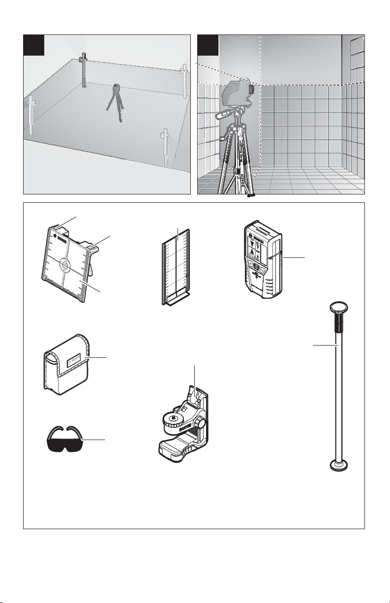
15 Laser target plate
16 Measuring plate with stand*
17 Laser receiver*
18 Protective pouch*
19 Universal holder*
20 Laser viewing glasses*
21 Tripod* (not shown)
*The accessories illustrated or described are
not included as standard delivery.
Working range (typical)
–Standard .................................... 65 ft (20m)
–With pulse function .................... 50 ft (15m)
–With laser receiver............16-260 ft (5-80m)
Leveling Accuracy
(typical) ..............................up to 1/4 at 100 ft
Self-leveling range (typical).......................±4°
Leveling duration, (typical) ...................... <4s
Operating temperature ........... 14 °F ~113 °F
(–10 °C ~ +45 °C)
Storage temperature............... -4 °F ~ 158 °F
(–20 °C ~ +70 °C)
Relative air humidity, max. ....................90 %
Laser class ................................................. 2
Laser type ...........................640 nm, <1 mW
Tripod mount .........................1/4-20, 5/8-11
Batteries ..........................4 x 1.5 V LR6 (AA)
Operating lifetime in operating mode
–With 2 laser planes..................................9 h
–With 1 laser plane .................................18 h
Weight ..................................... 1.54lb (700g)
Dimensions ........................ 6.2” x 5.5” x 2.1”
(159x 141 x 54mm)
Degree of protection ............................. IP 54
(dust and splash water protected)
1) The working range can be decreased by
unfavourable environmental conditions
(e.g. direct sun irradiation).
Please observe the article number on the
type plate of your tool. The trade names of
the individual tools may vary.
The tool can be clearly identified with the
serial number 14 on the type plate.
-7-

Operation
Initial Operation
• Loud audio signals will sound under
certain conditions while operating the
tool. Therefore, keep the tool away from
your ear or other persons. The loud
audio signal can cause hearing damage.
Protect the tool against moisture and
direct sun light.
• Do not subject the tool to extreme
temperatures or variations in
temperature.
As an example, do not leave it in vehicles
for longer periods. In case of large
variations in temperature, allow the
tool to adjust to the ambient temperature
before putting it into operation. In case of
extreme temperatures or variations in
temperature, the accuracy of the tool can
be impaired.
• Avoid heavy impact or dropping of the
tool. After heavy exterior impact on the
tool, an accuracy check should always be
carried out before continuing to work (see
“Leveling Accuracy”).
• Switch the tool off during transport.
When switching off, the leveling unit,
which can be damaged in case of intense
movement, is locked.
Switching On and Off
To switch on the tool, slide the On/Off
switch 7 to the “ on”. position (when
working without automatic levelling) or to the
“ on” position (when working with
automatic levelling). Immediately after
switching on, the tool sends laser beams out
of the exit openings 1.
• Do not point the laser beam at persons
or animals and do not look into the
laser beam yourself, not even from a
large distance.
To switch off the tool, slide the On/Off
switch 7 to the “off” position. When switching
off, the levelling unit is locked.
When exceeding the maximum permitted
operating temperature of 45 °C, the tool
switches off to protect the laser diode. After
cooling down, the tool is ready for operation
and can be switched on again.
Deactivating the Automatic Shut-off
When no button on the tool is pressed for
approx. 30 minutes, the tool automatically
switches off to save the batteries.
To switch on the tool after automatic shut-off,
either slide the On/Off switch 7 to the “off”
position and then switch the tool on again or
press the operating mode button 4 once or
press teh pulse-function button 3 once.
To deactivate the automatic shut-off, keep
the operating mode button 2 pressed for at
least 3 s (while the tool is switched on).
Deactivation of the automatic shut-off is
confirmed by brief flashing of the laser
beams.
• Do not leave the switched on tool
unattended and switch the tool off after
use.
To activate the automatic shut-off, switch the
tool off and then on again.
Deactivating the Signal Tone
After the tool has been switched on,the audio
signal is always activated.
To deactivate/activate the audio signal, press
and hold the operating mode button 4 and
the pulse-function button 3 at the same time
for at least 3 s.
The audio signal activation and deactivation
are both confirmed by three short beeps.
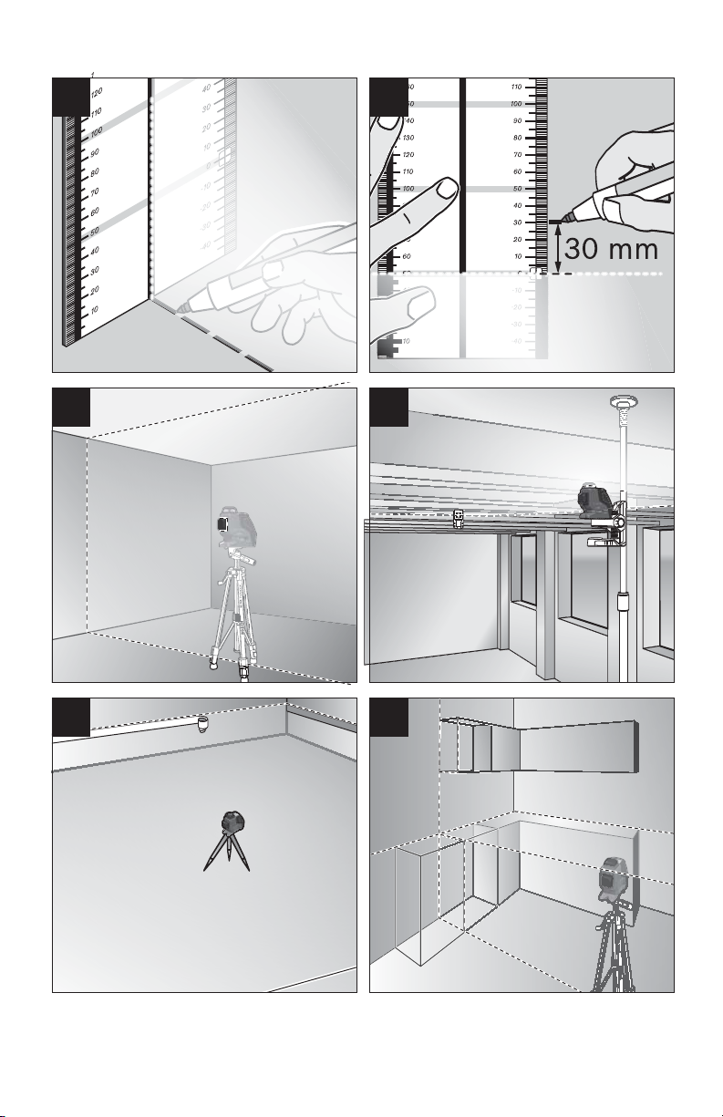
Operating Modes
The tool has three operating modes between
which you can switch at any time:
– Horizontal operation: generates a
horizontal laser plane.
– Vertical operation: generates a vertical
laser plane.
– Cross-line operation: generates a
horizontal and vertical laser plane.
After switching on, the tool is in horizontal
operation. Press the operating mode button
4 to change the operating mode.
All three operating modes can be selected
either with or without automatic levelling.
Pulse Function
When working with the laser receiver 17,
the pulse function must be activated,
–independent of the selected operating
mode.
In pulse function, the laser lines flash at very
high frequency and thus become detectable
by the laser receiver 17.
To switch on the pulse function, press button
3. When the pulse function is switched on,
the pulse-function indicator 5 lights up green.
-8-

When the pulse function is switched on, the
visibility of the laser lines is reduced for the
human eye. Therefore, shut off the pulse
function by pushing button 3 again when
working without laser receiver. When the
pulse function is switched off, the pulsefunction indicator 5 is deactivated.
Automatic Leveling
Working with Automatic Leveling
Position the tool on a level and firm support,
attach it to the holder 19 or to the tripod 21.
When working with automatic levelling, push
the On/Off switch 7 to the “ on” position.
After switching on, the leveling function
automatically compensates irregularities
within the self-leveling range of ±4°. The
leveling is finished as soon as the laser
beams do not move any more.
If automatic leveling is not possible, e.g.
because the surface on which the tool stands
deviates by more than 4° from the horizontal
plane, the laser lines begin to flash rapidly.
When the audio signal is activated, a fastbeat signal sounds for 30 s (maximum). This
alarm is deactivated within 10 s after
switching on, in order to allow adjustment of
the tool.
Set up the tool in level position and wait for
the self-leveling to take place. As soon as the
tool is within the self-leveling range of ±4°, all
laser beams light up continuously and the
audio signal is switched off.
In case of ground vibrations or position
changes during operation, the tool is
automatically levelled in again. To avoid
errors, check the position of the horizontal
and vertical laser
line with regard to the reference points upon
releveling.
Working without Automatic Leveling
For working without automatic leveling, slide
the On/Off switch 7 to the “ on” position.
When automatic leveling is switched off,
indicator 6 lights up red and for the first 30 s
laser beams flash slowly.
When the automatic leveling is switched off,
the tool can be held by hand or placed on an
inclined surface. In cross-line operation, the
two laser lines do not necessarily run at a
right angle to each other.
Working Advice
• Always use the center of the laser point
for marking. The size of the laser point
changes with the distance.
Leveling Accuracy
Influences on Accuracy
The ambient temperature has the greatest
influence. Especially temperature differences
occurring from the ground upward can divert
the laser beam.
Because the largest difference in
temperature layers is close to the ground,
the tool should always be mounted on a
tripod when distances exceeding 20 m. If
possible, also set up the tool in the center of
the work area.
Apart from exterior influences, devicespecific influences (such as heavy impact or
falling down) can lead to deviations.
Therefore, check the accuracy of the tool
each time before starting your work.
Firstly, check the leveling accuracy of the
horizontal laser line and then the leveling
accuracy of the vertical laser line.
Should the tool exceed the maximum
deviation during one of the tests, please
have it repaired by a Bosch after-sales
service.
Checking the Horizontal Leveling
Accuracy.
A free measuring distance of 16 ft on a firm
surface in front of two walls A and B is
required for the check.
– Mount the tool onto a tripod, or place it
on a firm and level surface close to the
wall A. Switch the tool on. Select crossline operation with automatic leveling.
B
16 ft (5m)
– Direct the laser against the close wall A
and allow the tool to level in. Mark the
center of the point where the laser lines
cross each other on the wall (point I).
-9-
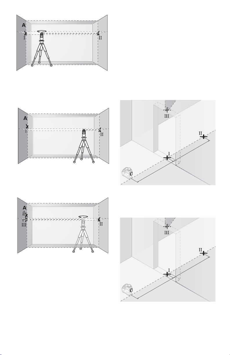
– Turn the tool by 180°, allow it to level in
B
180˚
B
B
dd
180˚
8ft
8ft
8ft
8ft
and mark the cross point of the laser lines
on the opposite wall B (point II).
– Without turning the tool, position it close to
wall B. Switch the tool on and allow it to
level in.
– Align the height of the tool (using a tripod
or by underlaying, if required) in such a
manner that the cross point of the laser
lines is projected against the previously
marked point II on the wall B.
32ft x ±0.0024in/ft = ±5/64 (0.078 in)
Thus, the difference d between points I and
III must not exceed 5/64 in (max.).
Checking the Leveling Accuracy of the
Vertical Line
For this check, a door opening is required
with at least 8 ft of space (on a firm surface)
to each side of the door.
– Position the tool on a firm, level surface
(not on a tripod) 8ft away from the door
opening. Allow the tool to level in while in
vertical operation with automatic leveling,
and direct the laser beam at the
door opening.
– Mark the center of the vertical laser line at
the floor of the door opening (point I), at a
distance of 8ft beyond the other side
of the door opening (point II) and at the
upper edge of the door opening (point III).
– Without changing the height, turn around
the tool by 180°. Direct it against the wall A
in such a manner that the vertical laser line
runs through the already marked point I.
Allow the tool to level in and mark the
cross point of the laser lines on the wall A
(point III).
– The difference d of both marked points I
and III on wall A results in the actual height
deviation of the tool alongside the
lateral axis.
On the measuring distance of 2 x 16ft = 32ft,
the maximum allowable deviation is:
– Rotate the tool by 180° and position it on
the other side of the door opening directly
behind point II. Allow the tool to level in
and align the vertical laser line in such a
-10-
 Loading...