


|
|
|
|
|
|
Vote |
for your |
at |
|||
|
year’ |
||||
‘Installer |
of the |
||||
|
|||||
|
-bosch.co.uk |
||||
|
|
||||
.worcester |
|
|
|||
www |
|
|
|
|
|
24CDi, 28CDi & 35CDi II COMBI

 Worcester supports the

Benchmark code of practice
|
G.C. NUMBERS |
|
|
APPLIANCE |
NATURAL GAS |
L.P.G. |
|
24CDi Fanned Flued (RSF) |
47 311 30 |
47 |
311 31 |
24CDi Balanced Flued (BF) |
47 311 29 |
|
|
24CDi Open Flued (OF) |
47 311 32 |
47 |
311 33 |
28CDi Fanned Flue (RSF) |
47 311 34 |
47 |
311 35 |
35CDi II Fanned Flue (RSF) |
47 311 58 |
47 |
311 59 |
USER INSTRUCTIONS & CUSTOMER CARE GUIDE

EXCELLENCE COMES
AS STANDARD
Thank you for purchasing a Worcester CDi gas-fired combination appliance.
The CDi appliances are made by Worcester and the strictest quality control standards are demanded throughout every stage of production.
Indeed, Worcester, part of the Bosch Group have led the field in innovative appliance design and performance for more than 40 years.
The result is that your new Worcester CDi appliance offers you the very best of everything - quality, efficiency, economical running costs, proven reliability and value for money.
What’s more, you also have the assurance of our nononsense 1 year parts and labour guarantee.
And, to keep your boiler operating at peak condition and efficiency, an optional maintenance scheme is available from Worcester. Contact our Service Contracts team on 01905 754624 for further details.
CONTENTS
Page No.
Operating Instructions
.................................... 3-11
Fault and Breakdowns 12
Maintenance and
Extended Warranty
Information ............ 13-14
Guarantee Details .. 15-16
2

GENERAL
INFORMATION
GAS SAFETY (INSTALLATION AND USE) REGULATIONS 1998
It is the law, in GB, that all gas appliances must be installed by a competent person in accordance with the above regulations. Failure to install appliances correctly could lead to prosecution. It is in your interest and that of safety to ensure compliance with the law. The manufacturer’s notes must not be taken, in any way, as over-riding statutory obligations.
In GB, a competent person is someone registered with CORGI. All CORGI registered installers carry a CORGI ID card and have a registration number. Both should be recorded in the BENCHMARK checklist. You can check that your installer is CORGI registered by calling CORGI on 01256 372300.
WARNING: This appliance must be earthed and protected by a 3 amp fuse.
ELECTRICITY SUPPLY: 230V ~ 50Hz
IMPORTANT: To get the best from your Worcester CDi please read these instructions carefully.
NOTE: In the event of a fault the appliance should not be used until the fault has been corrected by a competent person.
BENCHMARK 
The Benchmark initiative is a code of practice to encourage the correct installation, commissioning and servicing of domestic central heating boilers and system equipment.
A checklist can be found in the back of every installation manual. This is a vital document that needs to be completed by the installer at the time of installation. It confirms that the boiler has been installed and commissioned according to the manufacturers instructions.
In Eire the declaration found in IS 813 must be completed. Without completion of the checklist and/or declaration, manufacturers may refuse to respond to a call-out request. It is important that the checklist and/or declaration are fully completed by your installer.
GENERAL DESCRIPTION
(See Fig.1.)
The WORCESTER CDi MODELS are combined domestic hot water and central heating appliances. They consist of a gas fired boiler having a varying output of between:
|
CH |
|
DHW |
24CDi |
9.0 - 24kW |
9.0 - 24kW |
|
28CDi |
9.0 - 24kW |
9.0 |
- 28kW |
35CDi II |
10.5 - 27.5kW |
9.5 - |
35.3kW |
a heat exchanger to provide domestic hot water via the boiler, circulating pump and water diverting valve. All the necessary controls to provide mains fed domestic hot water and central heating.
The appliances are supplied as standard with a manual operating switch. Alternatively a facia mounted programmer may have been fitted.
The appliances can operate in one of two modes. Hot water only or hot water and central heating.
3
Hot Water Mode:
The appliance operates to supply only domestic hot water when the heating temperature mode is fully anti-clockwise, at the – position or the timer is programmed to OFF mode.
A flow restrictor is fitted within the appliance which limits a hot water delivery rate to a maximum of:
24CDi |
9.0 (±15%) litres/minute |
28CDi |
10.0 (±15%) litres/minute |
35CDi II 12.0 (±15%) litres/minute
Hot Water and Central Heating mode:
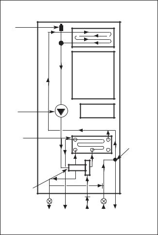
Fig. 1. System Diagram.
Automatic air vent

 Gas to water heat exchanger
Boiler
Circulating
pump 
 Expansion vessel
Water to |
Pressure |
|
water heat |
||
relief valve |
||
exchanger |
||
|
Diverter valve
CH |
Domestic |
Domestic CH |
Safety dis- |
flow |
hot water |
cold supreturn |
charge |
|
out |
ply |
|
When a demand is made for heating by the system controls (i.e. a programmer or room thermostat), the pump will energise, circulating primary water around the heating system and the burner will light. The heat output from the appliance in this mode has been factory set to maximum. The appliance will operate as necessary to maintain the temperature of the radiators at the level set by the adjustment of the Heating Temperature Control Knob. (See Fig. 2.)
If the system no longer requires output to maintain the desired room temperature, the burner will extinguish. The pump will continue to run for a short period to dissipate the residual heat from the appliance and then switch off.
The appliance will supply heat to the central heating system as required. A demand for hot water at a tap or shower will override the central heating function for the period of the domestic hot water demand.
4

GENERAL NOTES
CENTRAL HEATING SYSTEM
During the first few hours of operation of the central heating system, check that all radiators are being heated at an even rate. Should the upper area of a radiator be at a lower temperature than the base of the radiator, it should be vented by releasing air through the venting screw at the top of each radiator. Make sure your installer shows you how to carry out the operation. Repeated venting will reduce the quantity of water in the system and this must be replenished for safe and satisfactory operation of the appliance. Should water leaks be found in the system or excessive venting be required from any radiator, your installer or heating engineer should be contacted and the system corrected.
Fig. 1a. |
SEALED HEATING SYSTEM |
|
The appliance can be fitted to a sealed heating sys- |
||
|
||
|
tem which is pre-pressurised. In this case your installer |
|
|
will advise you on the minimum and maximum pres- |
|
|
sure that should be indicated on the pressure gauge. See |
|
|
Fig. 2. Check regularly that this pressure is maintained |
|
|
and contact your installer or maintenance engineer if |
|
|
there is a permanent significant drop in pressure indi- |
|
|
cated on the gauge. If the system loses pressure it |
|
|
should be re-pressurised as instructed by the installer |
|
|
(N.B. Maximum operating pressure 2.5 bar). |
|
|
Re-pressurising The System (See Fig. 1a). |
|
|
(If in doubt leave this procedure to your installer). |
|
|
Remove the bottom panel to gain access to the fill- |
|
|
ing loop assembly. |
|
|
Insert the bayonet end of the filling key into the |
|
|
corresponding cut outs in the filling loop housing and |
|
Grey |
twist to lock the key in place. |
|
Turn the grey knob anti-clockwise to allow water |
||
Knob |
||
ingress and fill until the required pressure is reached. |
||
|
||
|
Turn the grey knob clockwise to stop filling and |
|
|
remove the filling key by lining up the bayonet end of |
|
Filling Key |
the key with the cut outs in the filling loop housing and |
|
|
withdrawing the key. |
|
|
N.B. The key must always be removed from the |
|
|
filling loop housing after the system has been filled to |
|
|
prevent accidental filling and to comply with Bylaw 14 |
|
|
of the Water Bylaws Scheme. |
|
|
Store the key in a safe place for future use and |
|
|
refit the bottom panel. |
|
|
OPEN VENTED HEATING SYSTEM |
|
|
The appliance may be fitted to an open vented |
|
|
heating system your installer will advise you. There is |
|
|
no need to observe the pressure gauge. |
5
 Loading...