


SMARTSCAN-AUTODIAGNOSTICTOOL
INSTRUCTIONMANUAL
Catalog
Number
AD925
0.3 II OBD
Thank you for choosing Black & Decker!
To register your Smart Scan™ Car Diagnostic Tool and access your ability to look up codes go to www.smartscan.net
PLEASE READ BEFORE RETURNING THIS
PRODUCT FOR ANY REASON:
If you have a question or experience a problem with your Black & Decker purchase, go to
HTTP://WWW.BLACKANDDECKER.COM/INSTANTANSWERS for instant answers 24 hours a day.
If you can’t find the answer or do not have access to the internet,
call 1-800-544-6986 from 8 a.m. to 5 p.m. EST Mon. -- Fri. to speak with an agent. Please have the catalog number available when you call.
 WARNING: Read the Instruction Manual completely before operating the Tool. An undetected or uncorrected vehicle malfunction could cause a serious, even fatal, accident. Important Safety Information in the User’s Manual is intended to protect the user, bystanders and the user’s vehicle.
SAVE THIS INSTRUCTION MANUAL FOR FUTURE REFERENCE.
VEA EL ESPAÑOL EN LA CONTRAPORTADA.
INSTRUCTIVO DE OPERACIÓN, CENTROS DE SERVICIO Y PÓLIZA DE GARANTÍA. ADVERTENCIA: LÉASE ESTE INSTRUCTIVO ANTES DE USAR EL PRODUCTO.

Contents |
|
Safety Guidelines - Definitions......................................................... |
2 |
Safety Precautions ......................................................................... |
3 |
About Smart Scan............................................................................ |
3 |
Functional Description ...................................................................... |
4 |
Retrieving Diagnostic Codes.............................................................. |
5 |
Reading Codes................................................................................ |
6 |
Erasing Diagnostic Codes................................................................ |
7 |
Operating on Battery Power............................................................. |
8 |
Inserting the Batteries...................................................................... |
8 |
What Are Diagnostic Trouble Codes................................................ |
9 |
Understanding DTCs........................................................................ |
10 |
First Character - System.................................................................. |
10 |
Second Character - Sub-System..................................................... |
10 |
Third Character - Sub-System......................................................... |
10 |
Fourth and Fifth Characters............................................................. |
10 |
Most Common Generic DTCs......................................................... |
10 |
Troubleshooting .............................................................................. |
12 |
Service Information.......................................................................... |
13 |
Full Two - Year Home Use Warranty ................................................ |
13 |
SAFETY GUIDELINES - DEFINITIONS
It is important for you to read and understand this manual. The information it contains relates to protecting YOUR SAFETY and PREVENTING PROBLEMS. The symbols below are used to help you recognize this information.
 DANGER: Indicates an imminently hazardous situation which, if not avoided, will result in death or serious injury.
 WARNING: Indicates a potentially hazardous situation which, if not avoided, could result in death or serious injury.
 CAUTION: Indicates a potentially hazardous situation which, if not avoided, may result in minor or moderate injury.
CAUTION: Used without the safety alert symbol indicates a potentially hazardous situation which, if not avoided, may result in property damage.
NOTE: Indicates a condition which, if not avoided, may result in damage or lost information.
2
Safety Precautions
This Instruction Manual describes the features of the Tool and provides step-by-step instructions for operating the Tool. Read, understand, and follow all safety messages and instructions in the manual before operating the Tool. Always refer to and follow safety messages and test procedures provided by the manufacturer of the vehicle and the Tool.
 WARNING: This Tool may not detect every malfunction. Do not take chances with brakes, steering, or other vital functions of your vehicle, as a serious accident could result.
 WARNING: This product contains chemicals, including lead, known to the State of California to cause cancer, and birth defects or other reproductive harm. Wash hands after handling.
 GENERAL SAFETY WARNINGS AND INSTRUCTIONS
•Always wear ANSI approved goggles for eye protection.
•Operate vehicle in a well-ventilated area. Never turn engine on inside an enclosed space.
•Keep people and equipment away from all moving or hot engine parts.
•Before testing vehicle, make sure the transmission is in PARK (automatic transmission) or Neutral (manual transmission) and the parking brake is set. Block the drive wheels.
•Keep a fire extinguisher suitable for gasoline/electrical/ chemical fires readily available.
•Never leave the vehicle unattended while testing.
•Never lay tools on the vehicle battery.
•Use caution when working around ignition coil, distributor cap, ignition wires, and spark plugs. Components can produce a high voltage while engine is running.
•Battery acid can burn. If contacted, rinse with water or neutralize with a mild base such as baking soda. If you splash your eyes, flush with water and call a physician immediately.
•Never smoke or have open flames near vehicle. Vapors from gasoline and battery are explosive.
•Do not use the Tool if internal circuitry has been exposed to moisture. Internal shorts could cause a fire and damage.
•Always turn ignition key OFF when connecting or disconnecting electrical components, unless otherwise instructed.
•Most vehicles are equipped with air bags. If you elect to work around air bag components or wiring, follow your vehicle’s service manual cautions. You could be seriously injured or killed by an unintended deployment.
 WARNING: The air bag can still open several minutes after ignition is turned off.
• Always follow vehicle manufacturer’s warnings, cautions, and service procedures.
Liquid Crystal Display (First Aid Measures)
•If liquid crystal comes in contact with your skin:
Wash area off completely with plenty of water. Remove contaminated clothing.
•If liquid crystal gets into your eye:
Flush the affected eye with clean water and then seek medical attention.
•If liquid crystal is swallowed:
Flush your mouth thoroughly with water. Drink large quantities of water and induce vomiting. Then seek medical attention.
3
About Smart Scan - Auto Diagnostic Tool
The Tool retrieves Diagnostic Trouble Codes (DTCs) from the vehicle’s computer modules.
Once the diagnostic codes has been retrieved from the vehicle’s computer modules, you can:
•View the findings.
•Erase the DTCs from the vehicle’s computer modules.
•Run diagnostics again by rescanning the vehicle’s computer modules.
•Operate the Tool on battery power.
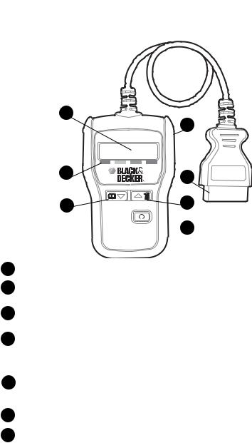
FUNCTIONAL DESCRIPTION
1
|
4 |
2 |
5 |
|
0.3 II DBO
 7
7
1 |
with 8 characters. |
2Urgency Rating Indicators - Shows the Urgency Rating associated with the DTC on the Display.
3 |
READ/Scroll Down Key - To view the |
DTC or to rescan the vehicle’s |
|
computer modules for the latest DTCs. |
|
4 |
USB Port - Used to update the Tool’s software. The USB cable is not |
|
|
included but can be purchased at a |
computer retailer. The Tool uses a |
|
USB cable with an A connector on one |
and a mini-B connector on the |
|
other end. |
|
5 |
OBD II Connector - Used to |
with OBD II compliant vehicles by |
|
plugging into the vehicle’s Data Link Connector usually located under the |
|
dash on the driver’s side.
6ERASE/Scroll Up Key - To review previously viewed DTCs or to erase DTCs.
Power On/Off Key - Turns Tool on to review results away from the vehicle
7(batteries required).
4
Retrieving Diagnostic Codes
To retrieve your vehicle’s diagnostic codes:
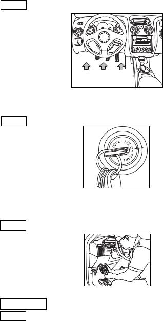
1. Locate the vehicle’s Data Link Connector.
The vehicle’s Data Link Connector (DLC) should be located under the dashboard on the driver’s side of the vehicle. If the DLC is not located under the dashboard, a label describing the location of the DLC should be there.
Visit the Links page on www.blackanddecker.com for further help in locating NOTE: the connector.
|
III I I I I I |
III |
|
|
|
II |
|
||
I |
II |
|
III I I I IIII |
|
I |
|
I |
II |
I |
II |
|
|
|
|
I |
|
I |
|
|
I |
|
I |
|
|
I |
|
I |
|
|
I |
|
|
|
|
2. Turn ignition switch to the ON position.
For a correct reading for Diagnostic Trouble Codes, the ignition key must be in the ON position. The engine does not require starting.
NOTE: Make sure the ignition key is in the ON, not the ACCESSORY position.
3. Plug the Tool into the vehicle’s DLC.
Take the OBD II connector on the Tool and plug it into the vehicle’s DLC.
The Tool retrieves diagnostic codes from the vehicle’s computer modules as soon as the Tool is connected.
Connecting the Tool to your vehicle will overwrite the diagnostic codes NOTE: previously stored on the Tool.
4. The Tool automatically establishes communication with the vehicle.
READING “READING” is displayed while the Tool begins communicating with the vehicle’s computer modules.
NOTE: If communication fails, the Tool’s display will switch (toggle) between displaying “Link” and “Error”. See Troubleshooting on page 12 for more
information on how to fix a link error.
5
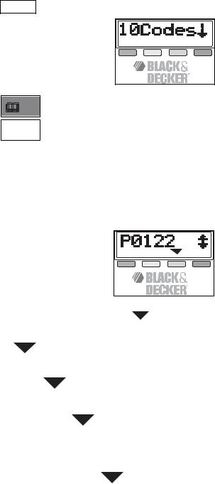
5. The Code Summary Screen appears.
The Summary Screen appears indicating how many codes were found. You must scroll down to view all the diagnostic codes.
If no Diagnostic Trouble Codes were found, the Tool will display “No Codes” NOTE: and point at the Green Urgency Rating.
6. To view the diagnostic codes about the vehicle press:
READ/Scroll Down key or the
 ERASE/Scroll Up key.
7. If you wish, you can rescan the vehicle.
Press and hold the READ/Scroll Down key for 3 seconds. Then repeat the instructions from step 5.
Reading Codes
Diagnostic Trouble Codes are used to help determine the cause of a problem or problems with a vehicle. Diagnostic Trouble Codes are set when a fault is present for a sufficient amount of time.
Urgency Ratings
An Urgency Rating (indicated by a |
) is provided for each Diagnostic Trouble Code: |
|||||||||
|
|
|
|
|
|
|
|
|
|
|
URGENCY RATING |
COLOR |
COURSE OF ACTION |
||||||||
1 |
|
|
|
|
|
|
|
|
Green |
No Trouble Codes present. |
|
|
|
|
|
|
|
|
|
|
|
|
|
|
|
|
|
|
|
|
|
|
2 |
|
|
|
|
|
|
|
|
Yellow |
Repair within a few days - not |
|
|
|
|
|
|
|
|
|
(Attention) |
dangerous to vehicle. |
|
|
|
|
|
|
|
|
|
|
|
3 |
|
|
|
|
|
|
|
|
Orange |
Get to a repair shop at your |
|
|
|
|
|
|
|
|
|
(Caution) |
earliest convenience so no |
|
|
|
|
|
|
|
|
|
|
further damage will be done |
|
|
|
|
|
|
|
|
|
|
to your vehicle. |
|
|
|
|
|
|
|
|
|
|
|
4 |
|
|
|
|
|
|
|
|
Red |
Immediate repair must be |
|
|
|
|
|
|
|
|
|
(Urgent) |
done to prevent further damage. |
|
|
|
|
|
|
|
|
|
||
|
|
|
|
|
|
|
|
|
|
|
|
|
|
|
|
|
|
|
|
|
|
|
|
|
|
|
|
|
|
|
6 |
|

If the Tool retrieves a Diagnostic Trouble Code that it does not understand, the Tool will still display the Diagnostic Trouble Code but it will not be able to display the Urgency Rating indicator ( ). If no Urgency Rating indicator is present, please contact the Customer Service Group at 1-800-544-6986 for further assistance.
NOTE: When multiple Diagnostic Trouble Codes with conflicting Urgency Ratings are reported, then follow the action for the highest Urgency Rating.
Erasing Diagnostic Codes
The Erase Codes function deletes the Diagnostic Trouble Codes from the vehicle’s computer modules. Erasing codes does not eliminate the problem. Over time, if there is a real problem, the code will be set again.
NOTE: Perform the Erase function only after the systems have been checked completely and the DTCs have been documented.
 WARNING: The Erase function should be performed with the Key in the ON position (not in the accessory position) and the Engine OFF. DO NOT START THE ENGINE.
To erase the diagnostic codes:
1. Locate the vehicle’s Data Link Connector.
The vehicle’s Data Link Connector (DLC) should be located under the dashboard on the driver’s side of the vehicle. If the DLC is not located under the dashboard, a label describing the location of the DLC should be there.
2. Turn ignition switch to the ON position. Make sure to leave the engine OFF.
NOTE: Make sure the ignition key is in the ON, not the ACCESSORY position.
3. Plug the Tool into the vehicle’s DLC.
Take the OBD II connector on the Tool and plug it into the vehicle’s DLC.
The Tool retrieves diagnostic codes from the vehicle’s computer modules as soon as the Tool is connected.
4. The Tool automatically establishes communication with the vehicle.
“READING” is displayed while the Tool begins communicating with the vehicle’s computer modules.
READING
NOTE: If communication fails, the Tool’s display will switch (toggle) between displaying “Link” and “Error”. See Troubleshooting on page 12 for more
information on how to fix a link error.
5. The Code Summary Screen appears.
The Summary Screen appears indicating how many codes were found. You must scroll down to view all the diagnostic codes.
If no Diagnostic Trouble Codes were found, the Tool will display “No Codes” NOTE: and point at the Green Urgency Rating.
6. Press and Hold the ERASE/Scroll Up key for 3 seconds.
A warning message appears asking you to confirm that you want to Erase the
diagnostic trouble codes.
ERASE?
To stop the ERASE operation and rescan the vehicle’s computer modules, press the READ/Scroll Down key.
7

7. Confirm your intentions by releasing, then pressing and holding the ERASE/Scroll Up key again for 3 seconds.
While the tool erases the diagnostic codes, the LCD displays the word “Erasing”.
ERASING
8. When all the codes have been erased, the word “Done” appears on the screen.
DONE
If the problem causing Diagnostic Trouble Code(s) still exists, the code will return. The Diagnostic Trouble Code may return immediately or may return after vehicle has been driven.
9. If you wish, you can rescan the vehicle.
Press the READ/Scroll Down key. When the Summary Screen appears, press the READ/Scroll Down key to view the updated findings.
Operating on Battery Power
The Tool must be connected to the vehicle initially to retrieve codes from the vehicle’s computer modules. Once information has been retrieved from the vehicle, the codes can be reviewed at any time by operating the Tool on battery power.
Inserting the Batteries
The Tool requires 4-AAA alkaline batteries to operate without vehicle power.
•Rechargeable batteries do not last as long as alkaline types and are not recommended.
•Non-rechargeable Lithium (Li) batteries can be used. While lithium-type batteries last longer than the alkaline type batteries, they are more expensive.
1.Remove the battery cover.
•Press the battery door latch located on the back of the unit.
•Remove the battery cover.
2.Install the new batteries.
•4-AAA alkaline batteries.
•Observe polarity identified inside the Tool’s battery compartment.
 WARNING: Batteries can explode, or leak, and can cause injury or fire. To reduce this risk:
•Carefully follow all instructions and warnings on the battery label and package.
•Always insert batteries correctly with regard to polarity (+ and -), marked on the battery and the equipment.
•Do not short battery terminals.
•Do not charge batteries.
•Do not mix old and new batteries. Replace all of them at the same time with new batteries of the same brand and type.
•Remove dead batteries immediately and dispose of per local codes.
•Do not dispose of batteries in fire.
•Keep batteries out of reach of children.
8

•Remove batteries if the device will not be used for several months.
“Transporting batteries can possibly cause fires if the battery terminals inadvertently come in contact with conductive materials such as keys, coins, hand tools and the like. The US Department of Transportation Hazardous Material Regulations (HMR) actually prohibit transporting batteries in commerce or on airplanes (i.e. packed in suitcases and carry on luggage) UNLESS they are properly protected from short circuits. So when transporting individual batteries, make sure that the battery terminals are protected and well insulated from materials that could contact them and cause a short circuit.”
To operate the Tool on Battery Power:
1. Disconnect the Tool from the vehicle.
Unplug the OBD II Connector from the vehicle’s DLC.
2. Turn On the Power.
• Press and hold down the Power On/Off key.
• The Tool warms up and displays the most recently retrieved Trouble Codes.
3. Review the data:
 READ/Scroll Down key or the
 ERASE/Scroll Up key.
NOTE: The Tool has a backlit LCD. When using the Tool under battery power:
|
Key Presses |
Display Response |
|
|
|
No key press in a 1-minute period |
Tool turns off LCD backlighting to conserve |
|
|
|
|
battery power. |
|
|
|
|
|
|
|
|
No key presses after 2 minutes |
Tool will power off. |
|
|
|
Key pressed prior to the Tool |
LCD backlight turns back on. |
|
|
|
powering off |
|
|
4. |
|
|
|
|
|
Power Down the Tool. |
|
|
||
|
|
|
||
When you are done reviewing the diagnostic codes, press and hold the Power On/Off key to turn off the Tool.
The Tool will store the findings in the Tool’s internal memory until the next time you connect to a vehicle.
If you plug the Tool back into a vehicle, the Tool will update the diagnostic codes stored in the Tool’s internal memory with the latest diagnostic codes from the vehicle’s computer modules.
Because some problems must be present over time before a code is reported, you may get slightly different results.
What Are Diagnostic Trouble Codes
Diagnostic Trouble Codes (DTCs) are used to determine what is wrong with a vehicle. Some DTCs are defined by the Society of Automotive Engineers (SAE). DTCs not assigned or reserved by the SAE are reserved for the vehicle manufacturer. These codes are referred to as Manufacturer Specific Codes.
9
Understanding DTCs
DTCs are five (5) character codes that automobile manufacturers use to relate to a component, sensor, or other part of the vehicle when the Check Engine/Service Engine Soon light turns on. Each DTC breaks down as follows:
First Character - System
•P = Power train
•B = Body
•C = Chassis
•U = Network
For example: P0107
If you get a P0107 code, the first character is a “P” which indicates that the Check Engine/ Service Engine Soon light is related to the vehicle’s Power train.
Second Character - Sub-System
The second character identifies whether the DTC is a generic code (the same for all OBD II equipped vehicles), or a manufacturer-specific code.
•0 = Generic
•1 = Manufacturer Specific
•2 = Generic
•3 = Generic / Manufacturer Specific
For example: P0107
If you get a P0107 code, the second character is a “0” which indicates that this DTC is generic or a standard DTC used by all vehicle manufacturers. This is good to know if you want to troubleshoot the problem yourself.
For example: P1402
If you get a P1402 code, the second character is a “1” which indicates that this DTC is a manufacturer-specific code reserved for the original equipment manufacturer (OEM). Manufacturers specific codes are not mandated by the SAE. Therefore, each OEM may have their own standard for defining the codes.
Third Character - Sub-System
The third character indicates the vehicle area (fuel or air emission management, ignition, idle control, transmission) that generated the DTC.
Fourth and Fifth Characters
The fourth and fifth characters define the malfunction that has triggered the DTC.
Most Common Generic DTCs
The table below lists the 75 most common Generic DTCs.
|
DTC |
Description |
|
P0031 |
Heated Oxygen Sensor Heater Control Circuit Low (Bank 1, Sensor 1) |
|
P0100 |
Mass or Volume Air Flow A Circuit |
|
P0101 |
Mass or Volume Air Flow A Circuit Range/Performance |
|
P0102 |
Mass or Volume Air Flow A Circuit Low Input |
|
P0107 |
Manifold Absolute Pressure/Barometric Pressure Sensor Low Input |
|
P0108 |
Manifold Absolute Pressure/Barometric Pressure Sensor High Input |
|
P0110 |
Intake Air Temperature Sensor 1 Circuit |
|
P0113 |
Intake Air Temperature Sensor 1 Circuit High Input |
|
P0115 |
Engine Coolant Temperature Sensor 1 Circuit |
|
P0117 |
Engine Coolant Temperature Sensor 1 Circuit Low Input |
|
P0118 |
Engine Coolant Temperature Sensor Circuit High Voltage |
|
P0120 |
Throttle/Pedal Position Sensor A Circuit |
|
P0121 |
Throttle/Pedal Position Sensor A Circuit Range/Performance |
|
P0122 |
Throttle/Pedal Position Sensor A Circuit Low Input |
|
P0123 |
Throttle/Pedal Position Sensor A Circuit High Input |
|
P0125 |
Insufficient Coolant Temperature for Closed Loop Control |
|
P0128 |
Coolant Thermostat (Coolant Temperature Below Thermostat Regulating |
|
|
Temperature) |
|
|
10 |
DTC |
Description |
|
|
P0130 |
Oxygen Sensor Circuit/Heater (Bank 1, Sensor 1) |
|
|
P0131 |
Oxygen Sensor Circuit/Heater Low Voltage (Bank 1, Sensor 1) |
|
|
P0132 |
Oxygen Sensor Circuit High Voltage (Bank 1, Sensor 1) |
|
|
P0133 |
Oxygen Sensor Circuit/Heater Slow Response (Bank1, Sensor 1) |
|
|
P0134 |
Oxygen Sensor Circuit No Activity Detected (Bank 1, Sensor 1) |
|
|
P0135 |
Oxygen Sensor Heater Circuit (Bank 1, Sensor 1)P0031 Heated |
|
|
|
|
Oxygen Sensor Heater Control Circuit Low (Bank 1, Sensor 1) |
|
P0136 |
Oxygen Sensor Circuit/Heater (Bank 1, Sensor 2) |
|
|
P0137 |
Oxygen Sensor Circuit/Heater Low Voltage (Bank 1, Sensor 2) |
|
|
P0138 |
Oxygen Sensor Circuit/Heater High Voltage (Bank 1, Sensor 2) |
|
|
P0140 |
Oxygen Sensor Circuit/Heater No Activity Detected (Bank 1, Sensor 2) |
|
|
P0141 |
Oxygen Sensor Heater Circuit (Bank 1, Sensor 2) |
|
|
P0151 |
Oxygen Sensor Circuit Low Voltage (Bank 2, Sensor 1) |
|
|
P0153 |
Oxygen Circuit Slow Response (Bank 2, Sensor 1) |
|
|
P0155 |
Oxygen Sensor Heater Circuit (Bank 2, Sensor 1) |
|
|
P0158 |
Oxygen Sensor Circuit High Voltage (Bank 2, Sensor 2) |
|
|
P0161 |
Oxygen Sensor Heater Circuit (Bank 2, Sensor 2) |
|
|
P0170 |
Fuel Trim (Bank 1) |
|
|
P0171 |
Bank 1 System Too Lean |
|
|
P0172 |
Bank 1 System Too Rich |
|
|
P0174 |
Bank 2 System Too Lean |
|
|
P0175 |
Bank 2 System Too Rich |
|
|
P0300 |
Random - Multiple Misfire Detected |
|
|
P0301 |
Cylinder 1 Misfire Detected |
|
|
P0302 |
Cylinder 2 Misfire Detected |
|
|
P0303 |
Cylinder 3 Misfire Detected |
|
|
P0304 |
Cylinder 4 Misfire Detected |
|
|
P0305 |
Cylinder 5 Misfire Detected |
|
|
P0306 |
Cylinder 6 Misfire Detected |
|
|
P0307 |
Cylinder 7 Misfire Detected |
|
|
P0308 |
Cylinder 8 Misfire Detected |
|
|
P0320 |
Ignition/Distributor/Crankshaft Sensor/Engine Speed Input Circuit |
|
|
P0325 |
Knock Sensor 1 Circuit (Bank 1) |
|
|
P0335 |
Crankshaft Position Sensor A Circuit Malfunction |
|
|
P0336 |
Crankshaft Position Sensor A Circuit Range/Performance |
|
|
P0400 |
Exhaust Gas Recirculation Flow |
|
|
P0401 |
Exhaust Gas Recirculation Flow Insufficient Detected |
|
|
P0402 |
Exhaust Gas Recirculation Flow Excessive Detected |
|
|
P0403 |
Exhaust Gas Recirculation Control Circuit |
|
|
P0404 |
Exhaust Gas Recirculation Control Circuit Range/Performance |
|
|
P0405 |
Exhaust Gas Recirculation Sensor A Circuit Low |
|
|
P0406 |
Exhaust Gas Recirculation Sensor A Circuit High |
|
|
P0410 |
Secondary Air Injection System |
|
|
P0411 |
Secondary Air Injector Incorrect Flow |
|
|
P0420 |
Catalyst System Efficiency Below Threshold (Bank 1) |
|
|
P0421 |
Warm Up Catalyst Efficiency Below Threshold (Bank 1) |
|
|
P0422 |
Main Catalyst Efficiency Below Threshold (Bank 1) |
|
|
P0430 |
Catalyst System Efficiency Below Threshold (Bank 2) |
|
|
P0440 |
Evaporative Emission System |
|
|
P0441 |
Evaporative Emission System Incorrect Purge Flow |
|
|
|
|
|
|
|
|
11 |
|

DTC |
Description |
P0442 |
Evaporative Emission System Leak Detected (Small Leak) |
P0443 |
Evaporative Emission System Purge Control Valve Circuit |
P0446 |
Evaporative Emission System Vent Control Circuit |
P0449 |
Evaporative Emission Vent Valve Solenoid Malfunction |
P0452 |
Evaporative Emission System Pressure Sensor/Switch Low Input |
P0455 |
Evaporative Emission System Leak Detected (Gross Leak/No Flow) |
P0456 |
Evaporative Emission System Leak Detected (Very Small Leak) |
P0505 |
Idle Air/Speed Control System |
P0507 |
Idle Air/Speed Control System Revolutions Per Minute Higher Than |
|
Expected |
NOTE: Bank is a term used by car manufacturers to locate which row of cylinders on the engine is impacted by a malfunction. Bank 1 refers to the side of the
engine that contains cylinder 1. Bank 2 refers to the side of the engine that does not contain cylinder 1.
|
Troubleshooting |
|
Error Message |
Solution |
|
Screen toggles between “Link” and “Error” If the ignition is on, disconnect the Tool |
||
|
from the vehicle, turn the ignition off for |
|
|
10 seconds, turn the ignition back on |
|
|
and reconnect the Tool to the vehicle. |
|
|
Your vehicle may not be OBD II |
|
|
compliant/certified. Refer to the Vehicle |
|
|
Emissions Control Information |
|
|
Decal that is located in the engine |
|
|
compartment and verify that the |
|
|
vehicle is identified as “OBDII Certified”. |
|
|
If the decal does not identify |
|
|
the vehicle as such, this Tool will |
|
|
not work with your vehicle. |
|
|
|
|
While operating on battery |
Make sure the batteries have been |
|
power, no results are displayed. |
installed correctly. |
|
For assistance with your product, visit our website www.blackanddecker.com for the location of the service center nearest you or call the BLACK & DECKER help line at
1-800-544-6986.
Maintenance
Use only mild soap and damp cloth to clean the tool. Never let any liquid get inside the tool; never immerse any part of the tool into a liquid.
IMPORTANT: To assure product SAFETY and RELIABILITY, repairs, maintenance and adjustment should be performed by authorized service centers or other qualified service personnel, always using identical replacement parts.
Accessories
Recommended accessories for use with your tool are available from your local dealer or authorized service center. If you need assistance regarding accessories, please call:
1-800-544-6986.
 WARNING: The use of any accessory not recommended for use with this tool could be hazardous.
12

Service Information
All Black & Decker Service Centers are staffed with trained personnel to provide customers with efficient and reliable power tool service. Whether you need technical advice, repair, or genuine factory replacement parts, contact the Black & Decker location nearest you. To find your local service location, refer to the yellow pages directory under "Tools—Electric" or call: 1-800-544-6986 or visit www.blackanddecker.com
Full Two-Year Home Use Warranty
Black & Decker (U.S.) Inc. warrants this product for two years against any defects in material or workmanship. The defective product will be replaced or repaired at no charge in either of two ways.
The first, which will result in exchanges only, is to return the product to the retailer from whom it was purchased (provided that the store is a participating retailer). Returns should be made within the time period of the retailer’s policy for exchanges (usually 30 to 90 days after the sale). Proof of purchase may be required. Please check with the retailer for their specific return policy regarding returns that are beyond the time set for exchanges.
The second option is to take or send the product (prepaid) to a Black & Decker owned or authorized Service Center for repair or replacement at our option. Proof of purchase may be required. To find your local service location, refer to the yellow pages directory under "Tools—Electric" or call: 1-800-544-6986 or visit www.blackanddecker.com
This warranty does not apply to accessories. This warranty gives you specific legal rights and you may have other rights which vary from state to state or province to province. Should you have any questions, contact the manager of your nearest Black & Decker Service Center. This product is not intended for commercial use.
FREE WARNING LABEL REPLACEMENT: If your warning labels become illegible or are missing, call 1-800-544-6986 for a free replacement.
Imported by |
See ‘Tools- |
|
Electric’ |
||
Black & Decker (U.S.) Inc., |
– Yellow Pages – |
|
701 |
E. Joppa Rd. |
for Service & |
Towson, |
MD 21286 U.S.A. |
Sales |
13
SMARTSCAN-OUTILDE
DIAGNOSTICAUTOMATIQUE
MODED’EMPLOI
N° de catalogue AD925
0.3 II DBO
Merci d’avoir choisi Black & Decker! Pour enregistrer votre outil de diagnostic automobile Smart Scan™ et bénéficier de la possibilité de consulter des codes, consulter www.smartscan.net
ÀLIRE AVANT DE RETOURNER CE PRODUIT POUR QUELQUE RAISON QUE CE SOIT :
Si des questions ou des problèmes surgissent après l’achat d’un produit Black & Decker, consulter le site Web
HTTP://WWW.BLACKANDDECKER.COM/INSTANTANSWERS
pour obtenir des réponses instantanément 24 heures par jour.
Si la réponse est introuvable ou en l’absence d’accès à Internet, composer le 1-800-544-6986 de 8 h à 17 h HNE, du lundi au vendredi, pour parler avec un agent. Prière d’avoir le numéro de catalogue sous la main lors de l’appel.
 AVERTISSEMENT : Veuillez lire le manuel de l’utilisateur avant de vous servir de l’outil. Une défaillance de véhicule non détectée ou non corrigée peut causer
un accident sérieux, voire fatal. Les renseignements de sécurité du guide de l’utilisateur ont pour objectif de protéger l’utilisateur, les personnes se trouvant à proximité et le véhicule.
CONSERVER CE MANUEL POUR UN USAGE ULTÉRIEUR.
14
 Loading...