


Mini-Modem
JUNE 2001
MD1620A
MD1620A-JAP
Mini-Modem
(56 kbps Data/Fax Modem)
CUSTOMER SUPPORT INFORMATION
Order toll-free in the U.S. 24 hours, 7 A.M. Monday to midnight Friday: 877-877-BBOX
FREE technical support, 24 hours a day, 7 days a week: Call 724-746-5500 or fax 724-746-0746
Mail order: Black Box Corporation, 1000 Park Drive, Lawrence, PA 15055-1018
Web site: www.blackbox.com • E-mail: info@blackbox.com

1
MINI-MODEM (56 KBPS DATA/FAX MODEM)
FEDERAL COMMUNICATIONS COMMISSION
AND
INDUSTRY CANADA
RADIO FREQUENCY INTERFERENCE STATEMENTS
This equipment generates, uses, and can radiate radio frequency energy
and if not installed and used properly, that is, in strict accordance with the
manufacturer’s instructions, may cause interference to radio communication. It
has been tested and found to comply with the limits for a Class A computing
device in accordance with the specifications in Subpart J of Part 15 of FCC rules,
which are designed to provide reasonable protection against such interference
when the equipment is operated in a commercial environment. Operation of
this equipment in a residential area is likely to cause interference, in which case
the user at his own expense will be required to take whatever measures may be
necessary to correct the interference.
Changes or modifications not expressly approved by the party responsible
for compliance could void the user’s authority to operate the equipment.
This digital apparatus does not exceed the Class A limits for radio noise emission from
digital apparatus set out in the Radio Interference Regulation of Industry Canada.
Le présent appareil numérique n’émet pas de bruits radioélectriques dépassant les limites
applicables aux appareils numériques de classe A prescrites dans le Règlement sur le
brouillage radioélectrique publié par Industrie Canada.

2
MINI-MODEM (56 KBPS DATA/FAX MODEM)
NORMAS OFICIALES MEXICANAS (NOM)
ELECTRICAL SAFETY STATEMENT
INSTRUCCIONES DE SEGURIDAD
1. Todas las instrucciones de seguridad y operación deberán ser leídas antes
de que el aparato eléctrico sea operado.
2. Las instrucciones de seguridad y operación deberán ser guardadas para
referencia futura.
3. Todas las advertencias en el aparato eléctrico y en sus instrucciones de
operación deben ser respetadas.
4. Todas las instrucciones de operación y uso deben ser seguidas.
5. El aparato eléctrico no deberá ser usado cerca del agua—por ejemplo,
cerca de la tina de baño, lavabo, sótano mojado o cerca de una alberca,
etc..
6. El aparato eléctrico debe ser usado únicamente con carritos o pedestales
que sean recomendados por el fabricante.
7. El aparato eléctrico debe ser montado a la pared o al techo sólo como sea
recomendado por el fabricante.
8. Servicio—El usuario no debe intentar dar servicio al equipo eléctrico más
allá a lo descrito en las instrucciones de operación. Todo otro servicio
deberá ser referido a personal de servicio calificado.
9. El aparato eléctrico debe ser situado de tal manera que su posición no
interfiera su uso. La colocación del aparato eléctrico sobre una cama,
sofá, alfombra o superficie similar puede bloquea la ventilación, no se
debe colocar en libreros o gabinetes que impidan el flujo de aire por los
orificios de ventilación.

3
MINI-MODEM (56 KBPS DATA/FAX MODEM)
10. El equipo eléctrico deber ser situado fuera del alcance de fuentes de calor
como radiadores, registros de calor, estufas u otros aparatos (incluyendo
amplificadores) que producen calor.
11. El aparato eléctrico deberá ser connectado a una fuente de poder sólo
del tipo descrito en el instructivo de operación, o como se indique en el
aparato.
12. Precaución debe ser tomada de tal manera que la tierra fisica y la
polarización del equipo no sea eliminada.
13. Los cables de la fuente de poder deben ser guiados de tal manera que
no sean pisados ni pellizcados por objetos colocados sobre o contra ellos,
poniendo particular atención a los contactos y receptáculos donde salen
del aparato.
14. El equipo eléctrico debe ser limpiado únicamente de acuerdo a las
recomendaciones del fabricante.
15. En caso de existir, una antena externa deberá ser localizada lejos
de las lineas de energia.
16. El cable de corriente deberá ser desconectado del cuando el equipo
no sea usado por un largo periodo de tiempo.
17. Cuidado debe ser tomado de tal manera que objectos liquidos no sean
derramados sobre la cubierta u orificios de ventilación.
18. Servicio por personal calificado deberá ser provisto cuando:
A: El cable de poder o el contacto ha sido dañado; u
B: Objectos han caído o líquido ha sido derramado dentro
del aparato; o
C: El aparato ha sido expuesto a la lluvia; o
D: El aparato parece no operar normalmente o muestra un
cambio en su desempeño; o
E: El aparato ha sido tirado o su cubierta ha sido dañada.

4
MINI-MODEM (56 KBPS DATA/FAX MODEM)
TRADEMARKS
The trademarks mentioned in this manual are the sole
property of their owners.
NAMING CONVENTIONS USED IN THIS MANUAL
In the software you received, the Mini-Modem is called
the Multi-Modem or the MT5600ADX. This is the
correct software for your Mini-Modem.

5
MINI-MODEM (56 KBPS DATA/FAX MODEM)
CONTENTS
1. Specifications . . . . . . . . . . . . . . . . . . . . . . . . . . . 8
2. Introduction and Description . . . . . . . . . . . . . 14
2.1 Introduction. . . . . . . . . . . . . . . . . . . . . . . . . 14
2.2 Product Description . . . . . . . . . . . . . . . . . . 14
2.2.1 What Is in Your Modem Package? . . . 18
2.2.2 How to Use This Manual . . . . . . . . . . 19
3. Installation and Connection. . . . . . . . . . . . . . . 21
3.1 Before You Install . . . . . . . . . . . . . . . . . . . . 21
3.1.1 Safety Warnings. . . . . . . . . . . . . . . . . . 21
3.1.2 Computer . . . . . . . . . . . . . . . . . . . . . . 22
3.1.3 Serial Cable . . . . . . . . . . . . . . . . . . . . . 22
3.1.4 Telephone Line . . . . . . . . . . . . . . . . . 23
3.1.5 Communications Software . . . . . . . . . 24
3.1.6 Assemble the Modem . . . . . . . . . . . . . 24
3.2 Installing the Modem . . . . . . . . . . . . . . . . . 25
3.3 LED Indicators. . . . . . . . . . . . . . . . . . . . . . . 30
3.4 Is Your Mini-Modem Ready for Use? . . . . . 33
3.5 Operating Your Mini-Modem . . . . . . . . . . . 34
3.6 Software Configuration . . . . . . . . . . . . . . . . 36
3.7 Troubleshooting . . . . . . . . . . . . . . . . . . . . . 40

6
MINI-MODEM (56 KBPS DATA/FAX MODEM)
3.7.1 None of the LEDs Light When the
Modem Is On . . . . . . . . . . . . . . . . . . . 41
3.7.2 The Modem Does Not Respond to
Commands . . . . . . . . . . . . . . . . . . . . . 42
3.7.3 The Modem Dials But Cannot
Make a Connection. . . . . . . . . . . . . . . 47
3.7.4 The Modem Disconnects
While Online. . . . . . . . . . . . . . . . . . . . 52
3.7.5 The Modem Cannot Connect
When Answering. . . . . . . . . . . . . . . . . 54
3.7.6 Slow File Transfer . . . . . . . . . . . . . . . . 54
3.7.7 Losing Data . . . . . . . . . . . . . . . . . . . . . 55
3.7.8 Garbage Characters on the Monitor . 56
4. AT Commands, S-Registers, and Result Codes 58
4.1 AT Commands . . . . . . . . . . . . . . . . . . . . . . . 58
4.2 S-Registers. . . . . . . . . . . . . . . . . . . . . . . . . . . 98
4.3 Result Codes. . . . . . . . . . . . . . . . . . . . . . . . . 124
5. Testing Your Modem. . . . . . . . . . . . . . . . . . . . . 128
5.1 Local Analog Loopback Test/V.54 Loop 3 128
5.2 Digital Loopback Test/V.54 Loop 2
(Local/Manual). . . . . . . . . . . . . . . . . . . . . . 130
5.3 Digital Loopback Test/V.54 Loop 2
(Remote/Automatic) . . . . . . . . . . . . . . . . . 132

7
MINI-MODEM (56 KBPS DATA/FAX MODEM)
6. Service and Technical Support . . . . . . . . . . . . 135
6.1 Calling Black Box. . . . . . . . . . . . . . . . . . . . . 135
6.2 About the Internet. . . . . . . . . . . . . . . . . . . . 135
Appendix A: Tone-Dial Frequencies . . . . . . . . . . 136
Appendix B: Regulatory Information . . . . . . . . . 138
B.1 Single-User Software License Agreement . 138
B.2 FCC Regulations for Telephone Line
Interconnection . . . . . . . . . . . . . . . . . . . . . . 138
B.3 Canadian Limitations Notice . . . . . . . . . . . 139

8
MINI-MODEM (56 KBPS DATA/FAX MODEM)
1. Specifications
Server-to-Client Data Rates — K56flex speeds when
accessing an ISP-type K56flex server (actual speed
depend on server capabilities and line conditions)
Client-to-Client Data Rates — 33,600, 31,200, 28,800,
26,400, 24,000, 21,600, 19,200, 16,800, 14,400,
12,000, 9600, 7200, 4800, 2400, 1200, 0-300 bps
Data Rates (fax) — 14,400, 9600, 7200, 4800, 2400,
300 bps
Data Format — Serial, binary, asynchronous
Compatibility — K56flex, ITU V.42bis, V.42,
Enhanced V.34, AT&T V32terbo, ITU V.32bis,
V.32, V.22bis, V.22, Bell 212A and 103/113, ITU
V.17, Group 3 T.4, T.30 and EIA Class 1
NOTE
Though this modem is capable of 56-kbps download
government regulations, line impairments, public
telephone infrastructure, and other external technological
factors currently prevent maximum 56-kbps connections.
Fax Compatibility — CCITT V.17, Group 3, V.29,
V.27ter and EIA Class 1

9
MINI-MODEM (56 KBPS DATA/FAX MODEM)
Error Correction/Data Compression — V.42
(LAP-M or MNP 3 and 4), V.42bis (4:1
throughput), MNP 5 (2:1 throughput)
Speed Conversion — Serial-port data rates
adjustable to 300, 1200, 2400, 4800, 9600, 19,200,
38,400, 57,600, and 115,200 bps
Flow Control — Software XON/XOFF, Hardware
RTS/CTS
Mode of Operation — Fax on-line modes, and full
duplex over dial-up lines
Intelligent Features — Automatic or manual dialing,
automatic or manual answer, microprocessorcontrolled, EIA extended Automode, adaptive
line probing, automatic symbol rate and carrier
frequency during start-up, retrain and rate
renegotiation, autodial, redial, tone dial, dial
pauses, call status display, auto-parity and data-rate
selection, keyboard-controlled modem options,
nonvolatile memory and on-screen displays for
modem option parameters and four telephone
numbers/command lines of up to 40 characters
each
Command Buffer — 40 characters

10
MINI-MODEM (56 KBPS DATA/FAX MODEM)
Data Modulation — Trellis-Coded Modulation
(TCM) at K56flex, 33,600, 31,200, 28,800, 26,400,
24,000, 21,600, 19,200, 16,800, 14,400, 12,000,
and 9600 bps; Quadrature Amplitude Modulation
(QAM) at 9600 (non-trellis), 4800, and 2400 bps;
PSK at 1200 bps; FSK at 300 bps
Fax Modulation — V.17 TCM at 14400, 12000, 9600,
and 7200 bps; V.29 QAM at 9600 and 7200 bps;
V.27ter DPSK at 4800 and 2400 bps; V.21CH2 FSK
at 300 bps (Half Duplex)
Carrier Frequencies (Data) — 1800 Hz
V.32/V.32bis/V32terbo; Enhanced V.34/K56flex
Carrier Frequencies, 2400 & 1200 bps
(V.22bis/V.22 or Bell 212A Standard) — Transmit
Originate: 1200 Hz; Transmit Answer: 2400 Hz;
Receive Originate: 2400 Hz; Receive Answer:
1200 Hz
Carrier Frequencies, 300 bps (Bell Standard) —
1270 Hz Mark, 1070 Hz Space for Transmit
Originate; 2225 Hz Mark, 2025 Hz Space for
Receive Originate; 2225 Hz Mark, 2025 Hz Space
for Transmit Answer; 1270 Hz Mark, 1070 Hz
Space for Receive Answer

11
MINI-MODEM (56 KBPS DATA/FAX MODEM)
Carrier Frequencies, V.21 — 980 Hz Mark, 1180 Hz
Space for Transmit Originate; 1650 Hz Mark, 1850
Hz Space for Transmit Answer; 1650 Hz Mark,
1850 Hz Space for Receive Originate; 980 Hz
Mark, 1180 Hz Space for Receive Answer
Carrier Frequencies, V.23 — 390 Hz Mark, 450 Hz
Space for Transmit Originate; 1300 Hz Mark, 2100
Hz Space for Transmit Answer; 1300 Hz Mark,
2100 Hz Space for Receive Originate; 390 Hz
Mark, 450 Hz Space for Receive Answer
Carrier Frequencies, Fax — V.21 CH2: Transmit
Originate: 1650 Hz Mark, 1850 Hz Space; Half
Duplex: Transmit Answer: 1650 Hz Mark, 1850 Hz
Space; V.27ter: Originate/Answer: 1800 Hz; V.29
QAM: Originate/Answer: 1800 Hz; V.17 TCM:
Originate/Answer: 1800 Hz
Transmit Level — -10 dBm (dial-up)
Frequency Stability — ±0.01%
Receiver Sensitivity — -43 dBm under worst-case
conditions
AGC Dynamic Range — 43 dB

12
MINI-MODEM (56 KBPS DATA/FAX MODEM)
Interface — EIA RS232C/CCITT V.24
Connectors — DB25 (RS-232C) connector; Two
RJ-11 modular phone jacks (one for line, one for
telephone set), and power jack.
Diagnostics — Power-On Self-Test, Local Analog
Loop, Local Digital Loop, Remote Digital Loop.
Indicators — LEDs for Send Data, Receive Data,
Carrier Detect, various speed indicators, Off Hook,
Terminal Ready, Error Correction, Fax.
Controls — Power ON/OFF Switch
Speaker — 2-inch cone with software- or command-
controlled volume
Operating Temperature — 32 to 120°F (0 to 50°C)
Power Requirement — MD1620A: 115 VAC, 60 Hz,
0.3 amp (2-prong outlet-mounted transformer);
MD1620A-JAP: Input voltage: 100 VAC, Input
frequency: 60/50 Hz; Output voltage: 14 V,
714 mA; International models: 240V/50Hz
optional
Power Consumption — 5 Watts

13
MINI-MODEM (56 KBPS DATA/FAX MODEM)
Regulatory Compliance — UL, CUL, CSA, FCC
Size — 5.6"H x 4.25"W x 1.15"D
(14.8 x 10.8 x 2.9 cm)
Weight — 0.5 lb. (1.1 kg)

14
MINI-MODEM (56 KBPS DATA/FAX MODEM)
2. Introduction and Description
2.1 Introduction
This User’s Manual will help you install, configure, test
and use your Mini-Modem (56 kbps Data/Fax Modem).
2.2 Product Description
Your Mini-Modem incorporates a modem technology
called K56flex™ that enables Internet connections at
data rates up to 56 kbps over standard telephone lines.
(In the United States, FCC regulations limit transmission
speed to 53 kbps.) K56flex technology is able to propel
data downstream from the Internet to your computer at
speeds of up to 56 kbps because data is digitally encoded
instead of modulated. Upstream transmission, mostly
keystroke and mouse commands from your computer
to the central site, continues to flow at the conventional
data rate of 33.6 kbps.
Your Mini-Modem offers interactive automatic dialing,
as well as command mode option configuration. You
may store four command lines or telephone numbers,
of up to 40 characters each, in the modem’s nonvolatile
memory. The modem pulse or tone-dials, and recog-

15
MINI-MODEM (56 KBPS DATA/FAX MODEM)
nizes dial tones and busy signals for reliable call-progress
detection. The modem can detect AT&T calling card
tones. It is FCC-Registered for connection to telephone
networks without any Data Access Arrangements
(DAAs).
NOTE
Though this modem is capable of 56-kbps download
performance, government regulations, line impairments,
public telephone infrastructure, and other external
technological factors currently prevent maximum 56-kbps
connections.
The Mini-Modem is a desktop fax/modem for
compatible IBM Personal Computers. It provides
ial-up asynchronous communication capability with
other personal computers, terminals, on-line computer
services, or other types of computer systems.
Connection to the phone line and/or an attached
telephone device is made by RJ-11 modular connectors;
the PC connection is made via an RS-232C/V.24 serial
cable receptacle; and low-voltage DC power is supplied
to the Mini-Modem through a modular power-supply
connection included with the modem. All these
connections are located on the rear of the Mini-Modem.
Hardware installation procedures are described in
Chapter 3.

16
MINI-MODEM (56 KBPS DATA/FAX MODEM)
General features include:
• Compliance with major ITU-T, TIA, and EIA
international standards to ensure compatibility
with other modems.
• Distinguishes data and fax calls.
• Caller ID to identify your caller’s phone number
(available on U.S. products).
Data
• Supports K56flex
™
for data transmission speeds up
to 56 kbps, while maintaining compatibility with
lower-speed modems.
NOTE
The K56flex standard asymmetrically transfers data—
client downloads at speeds up to 56 kbps, client
uploads at speeds up to 33.6 kbps.
• Supports the enhanced ITU-T V.34 standard, with
data transmission speeds to 33.6 kbps, while also
maintaining compatibility with lower-speed
modems.
• Supports K56flex speeds plus 33.6K, 31.2K, 28.8K,
26.4K, 24K, 21.6K, 19.2K, 16.8K, 14.4K, 12K, 9.6K,
7.2K, 4.8K, 2.4K, 1.2K, and 0-300 bps.

17
MINI-MODEM (56 KBPS DATA/FAX MODEM)
• Automatic fallback to slower speeds in noisy line
conditions, and fall-forward to faster speeds as
conditions improve (line-quality monitoring).
• ITU V.42 LAP-M and MNP Class 3 and 4
error correction.
• ITU V.42bis (4-to-1) and MNP 5 (2-to-1)
data compression.
• MNP10 and MNP10EC
™
enhanced
Cellular Performance (error correction).
• H.324 compliant (videophone ready).
• Automatic disabling of compression when
transferring already-compressed files.
• Autodial, redial, pulse (rotary) and touch-tone
dial.
• Dial tone and busy signal detection for reliable
call-progress detection.
• Distinctive ring support to route voice, data,
or fax calls on a single phone line.
• Plug and Play (PnP) serial support.

18
MINI-MODEM (56 KBPS DATA/FAX MODEM)
• Flash-ROM upgradable.
• Compatibility with the standard AT command
set used by most communication programs.
Fax
• Supports V.17, Class 1/Group 3 fax
communication standards, allowing it to
communicate with other fax modems as
well as with fax machines.
• Sends and receives faxes from your computer
at 14,400 bps, 9600 bps, 7200 bps, 4800 bps,
2400 bps, or 300 bps.
2.2.1 W
HAT
I
SINYOURMODEMPACKAGE
?
Your Mini-Modem has several components:
• Mini-Modem (56 kbps Data/Fax Modem)
• DC power supply
• One set of four plastic feet
• Telephone cord
• This User Manual

19
MINI-MODEM (56 KBPS DATA/FAX MODEM)
• Communications Software
• One Set-Up diskette
If any of these items are missing, please contact Black
Box at 724-746-5500.
2.2.2 H
OW TOUSETHISMANUAL
This manual is divided into six chapters and two
appendixes:
• Chapter 1, Specifications, lists relevant technical
specifications for the Mini-Modem.
• Chapter 2, Introduction and Description, begins
with a short product introduction and description,
followed by a guide (which you are now reading)
to the use of this manual.
• Chapter 3, Installation and Connection,
documents the procedure for connecting the
Mini-Modem to your computer and to the phone
line. There is also a Troubleshooting section in
case your Mini-Modem is not operating properly.

20
MINI-MODEM (56 KBPS DATA/FAX MODEM)
• Chapter 4, AT Commands, S-Registers and Result
Codes, documents default and option AT
commands, S-Registers and Result Codes
supported by the Mini-Modem.
• Chapter 5, Testing Your Modem, covers the
modem’s built-in test features. These are: Poweron Self Test, Local Analog Loopback, Digital
Loopback and Remote Digital Loopback Tests.
We have included a description of each test
and how to use each test procedure.
• Chapter 6, Calling for Technical Support.
• Appendix A, Tone-Dial Frequencies.
• Appendix B, Regulatory Information.

21
MINI-MODEM (56 KBPS DATA/FAX MODEM)
3. Installation and Connection
3.1 Before You Install
3.1.1 S
AFETYWARNINGS
SAFETY WARNINGS
1. Never install telephone wiring during a lightning
storm.
2. Never install telephone jacks in wet locations unless
the jack is specifically designed for wet locations.
3. Never touch uninsulated telephone wires or
terminals unless the telephone line has been
disconnected at the network interface.
4. Use caution when installing or modifying telephone
lines.
5. Avoid using a telephone (other than a cordless type)
during an electrical storm. There may be a remote risk of
electrical shock from lightning.
6. Do not use the telephone to report a gas leak in the
vicinity of the leak.
In addition to the contents of the Mini-Modem
package, you will need the following equipment.

22
MINI-MODEM (56 KBPS DATA/FAX MODEM)
3.1.2 C
OMPUTER
The Mini-Modem can be connected to any computer
with an RS-232 serial port.
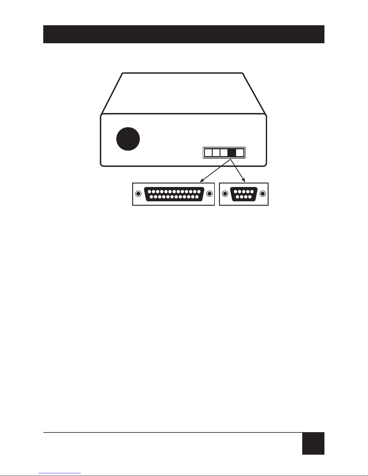
3.1.3 S
ERIALCABLE
You must provide a serial cable to connect the
Mini-Modem to your computer. Call Black Box at
724-746-5500 for ordering information. The cable must
have a DB25 male connector at the modem end. For
IBM and compatible computers, the other end may
have a DB25 male connector or a DB9 female
connector, depending on your particular computer
and whether you are using the COM1 or the COM2
serial port. The FCC requires cables to be shielded.
23
MINI-MODEM (56 KBPS DATA/FAX MODEM)
Figure 3-1. Serial Connectors on the PC.
3.1.4 T
ELEPHONELINE
You must have a telephone line with a conveniently
located connector (jack) to accept the cable that comes
with the Mini-Modem. If you do not have a telephone
jack near your computer, you should install an extension
before proceeding.
In North America, telephone extension kits and
accessories are available at electronics stores and
wherever telephones are sold. You may also hire an
independent contractor or your local telephone
company to do the work. If you want to add a line for

24
MINI-MODEM (56 KBPS DATA/FAX MODEM)
your Mini-Modem fax modem, you must contact
your telephone company.
3.1.5 C
OMMUNICATIONSSOFTWARE
To operate the Mini-Modem, you must have data and
fax communications software. Datacomm software
simplifies control of the modem by guiding you through
the process of selecting your serial port, your port speed,
and other variables, and then storing your settings,
including frequently called phone numbers, so they
can be recalled with the stroke of a key or the click
of a mouse. The software must be set up, or configured,
before you can use it. You must have Microsoft Windows
3.1 or later to run most prevalent software packages.
3.1.6 A
SSEMBLE THEMODEM
The only assembly required is to mount the feet on the
bottom of the modem. Simply peel the four self-adhesive
plastic feet off the backing strip and press them into the
recesses on the bottom of the modem. You can also use
self-adhesive Velcro patches (not included) to mount
the modem on a vertical surface or to keep it from being
dislodged on a horizontal surface.
25
MINI-MODEM (56 KBPS DATA/FAX MODEM)
If you use Velcro patches, we recommend that you
mount them where they will not obscure the labels on
the bottom of the modem. The Mini-Modem has no
special placement restrictions, but we recommend that
you place it where you can see the indicators on the
front panel.
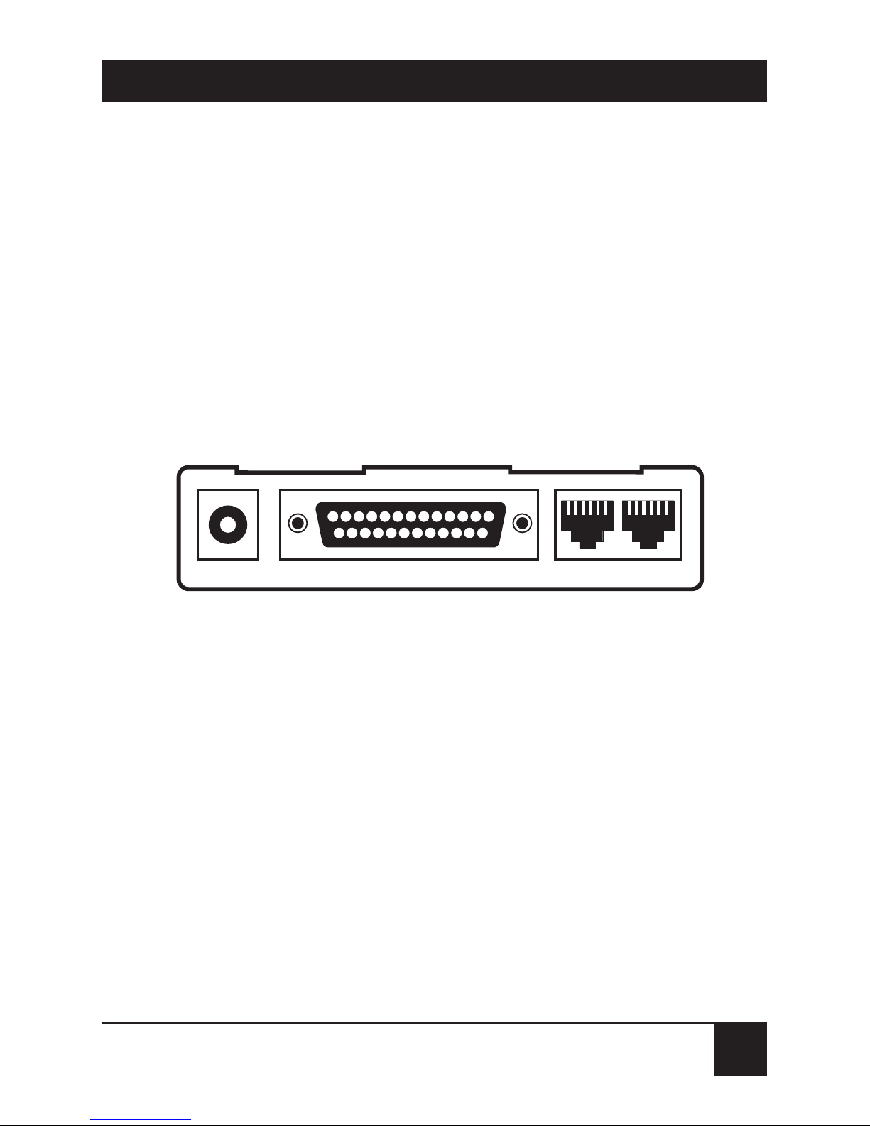
3.2 Installing the Modem
Figure 3-2. Mini-Modem Connections.
To install your Mini-Modem:
1. Attach the Mini-Modem to dial-up phone lines
using the RJ-11 telephone cord by plugging one
end of the cable provided with the Mini-Modem
into the telephone jack in your home or office,
and plugging the other end into the LINE jack
on the MiniModem.
POWER RS-232 PHONE LINE

26
MINI-MODEM (56 KBPS DATA/FAX MODEM)
NOTE
The LINE jack is not interchangeable with the PHONE
jack on the Mini-Modem. Do not plug the telephone into
the LINE jack or the line cable into the PHONE jack.
BABT regulations require that the telecommunication
cable be connected to the modem prior to being
connected to the network.
2. Attach your Mini-Modem to your PC or terminal
with an RS-232 (or V.24) cable (see Figure 3-1
and Figure 3-2). Be sure to tighten the mounting
screws on the DB connectors.
3. Connect your telephone set to phone jack
via RJ-11 cable.
4. Attach your Mini-Modem to the AC Power
transformer and plug the AC connector into
a live AC outlet.
NOTE
Use only the power supply provided with the Mini-Modem.
Using any other power supply could damage the modem.
5. Turn on power by flipping the “ON/OFF” switch
on the side of the Mini-Modem to the “ON”
position.

27
MINI-MODEM (56 KBPS DATA/FAX MODEM)
6. Make sure modem and computer/terminal serialport baud rates are adjusted. Note that several
programs can check this for you.
Install the Modem in Windows 95
If you are using Windows 95 or 98, you must install
the modem in the operating system. (If you are using
another operating system, you may skip this step.)
Adding the Mini-Modem to Windows 95 or 98
1. Click the Start button, point to Settings, and click
Control Panel.
2. Double-click the Modems icon. If no modem is
currently installed, the Install New Modem wizard
appears. If a modem is already installed, the
Modems Properties sheet appears; click Add
to go to the Install New Modem wizard.
3. Click Next in the Install New Modem wizard.
Windows searches for your new modem and
asks you to verify its selection.
NOTE
If Windows cannot find a modem, your modem may be
turned off, it may be plugged into the wrong connector
on your computer, or the serial cable may be faulty.

28
MINI-MODEM (56 KBPS DATA/FAX MODEM)
4. If Windows identifies your modem correctly as a
MultiModem MT5600ZDX, click Next to install
the modem. After the modem is installed, click
Finish to exit.
5. If Windows cannot identify your modem (for
instance, if it identifies your modem as a “Standard
Modem”), click Change. A dialog box with a list
of manufacturers and a list of modems appears.
6. Select “MultiTech Systems” from the
Manufacturers list box, then select “MultiModem
MT5600ZDX” from the Models list box.
7. Click Next. Windows installs and configures
the modem.
8. Click Finish to exit.
Removing Your Old Modem from Windows 95 or 98
When your Mini-Modem replaces another modem, the
old modem installation remains in Windows after you
install the new modem, and the old modem is still
selected in HyperTerminal and other Windows 95
applications. Although you can change the application
connection descriptions one at a time, it is easier to

29
MINI-MODEM (56 KBPS DATA/FAX MODEM)
force Windows 95 applications to use the Mini-Modem
by removing the old modem from Windows.
1. Click the Start button, point to Settings, and click
Control Panel.
2. Double-click the Modems icon to open the
Modems Properties sheet.
3. In the list box, select the old modem.
4. Click Remove, then click Close.
5. The next time you dial a HyperTerminal
connection, it will select your new modem
and ask you to confirm the selection.
Installing Your Modem in MS-DOS 5.0 or Higher
If you have MS-DOS 5.0 or higher, a program called
MSD.EXE [Microsoft Diagnostics] is in your DOS
directory. Typing MSD at the DOS prompt brings up
a screen that provides a variety of information about
your computer. Select COM ports and it lists information about your com port, e.g., UART Type, Address,
and IRQ, to name a few. Once you know your serial
port’s UART type, you can set your communications’s
software appropriately.)
 Loading...