


LE601A-R3
Black Box LE601A-R3, LE602A-R3, LE629A, LE620A, LE622A User Manual
...
CUSTOMER
SUPPORT
INFORMATION
To order or for technical support: Call 724-746-5500 or fax 724-746-0746
Technical support and fax orders 24 hours a day, 7 days a week
Phone orders 24 hours, 7 A.M. Monday to midnight Friday; Saturday 8 to 4 (Eastern)
Mail order: Black Box Corporation, 1000 Park Drive, Lawrence, PA 15055-1018
DECEMBER 1998
LE601A-R3 LE620A LE629A
LE602A-R3 LE622A LE630A
LE603A-R5 LE624A LE631A
LE604A-R4 LE626A LE632A
LE605A-R3 LE628A LE633A
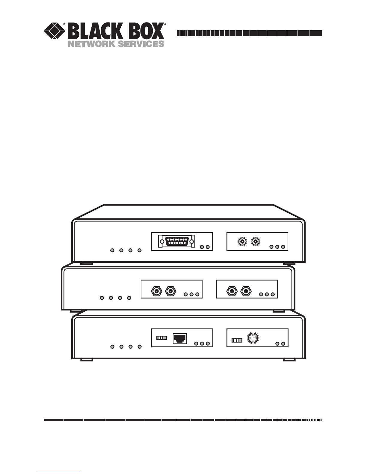
Local and Remote Repeaters
JABCOLRXPWR
Local Repeater
PART
RX
EXT
INT
LINK
PART
RX
JABCOLRXPWR
Remote Repeater-SM
LINK
PART
RX
TX
RX
LINK
PART
RX
TX
RX
JABCOLRXPWR
Remote Repeater
LINK
PART
RX
PART
RX

FCC AND DOC/MDC STATEMENTS
3
FEDERAL COMMUNICATIONS COMMISSION
AND
INDUSTRY CANADA
RADIO FREQUENCY INTERFERENCE STATEMENTS
This equipment generates, uses, and can radiate radio frequency
energy and if not installed and used properly, that is, in strict
accordance with the manufacturer’s instructions, may cause
interference to radio communication. It has been tested and found
to comply with the limits for a Class A computing device in
accordance with the specifications in Subpart J of Part 15 of FCC
rules, which are designed to provide reasonable protection against
such interference when the equipment is operated in a commercial
environment. Operation of this equipment in a residential area is
likely to cause interference, in which case the user at his own
expense will be required to take whatever measures may be
necessary to correct the interference.
Changes or modifications not expressly approved by the party
responsible for compliance could void the user’s authority to
operate the equipment.
This digital apparatus does not exceed the Class A limits for radio noise
emission from digital apparatus set out in the Radio Interference
Regulation of Industry Canada.
Le présent appareil numérique n’émet pas de bruits radioélectriques
dépassant les limites applicables aux appareils numériques de
classe A prescrites dans le Règlement sur le brouillage radioélectrique
publié par Industrie Canada.
TRADEMARK USED IN THIS MANUAL
ST is a registered trademark of AT&T.
Any other trademarks mentioned in this manual are acknowledged
to be the property of the trademark owners.

LOCAL AND REMOTE REPEATERS
NORMAS OFICIALES MEXICANAS (NOM) ELECTRICAL SAFETY STATEMENT
INSTRUCCIONES DE SEGURIDAD
1. Todas las instrucciones de seguridad y operación deberán ser leídas antes
de que el aparato eléctrico sea operado.
2. Las instrucciones de seguridad y operación deberán ser guardadas para
referencia futura.
3. Todas las advertencias en el aparato eléctrico y en sus instrucciones de
operación deben ser respetadas.
4. Todas las instrucciones de operación y uso deben ser seguidas.
5. El aparato eléctrico no deberá ser usado cerca del agua—por ejemplo,
cerca de la tina de baño, lavabo, sótano mojado o cerca de una alberca,
etc.
6. El aparato eléctrico debe ser usado únicamente con carritos o pedestales
que sean recomendados por el fabricante.
7. El aparato eléctrico debe ser montado a la pared o al techo sólo como
sea recomendado por el fabricante.
8. Servicio—El usuario no debe intentar dar servicio al equipo eléctrico más
allá a lo descrito en las instrucciones de operación. Todo otro servicio
deberá ser referido a personal de servicio calificado.
9. El aparato eléctrico debe ser situado de tal manera que su posición no
interfiera su uso. La colocación del aparato eléctrico sobre una cama,
sofá, alfombra o superficie similar puede bloquea la ventilación, no se
debe colocar en libreros o gabinetes que impidan el flujo de aire por los
orificios de ventilación.
10. El equipo eléctrico deber ser situado fuera del alcance de fuentes de
calor como radiadores, registros de calor, estufas u otros aparatos
(incluyendo amplificadores) que producen calor.
11. El aparato eléctrico deberá ser connectado a una fuente de poder sólo
del tipo descrito en el instructivo de operación, o como se indique en el
aparato.
4

NOM STATEMENT
12. Precaución debe ser tomada de tal manera que la tierra fisica y la
polarización del equipo no sea eliminada.
13. Los cables de la fuente de poder deben ser guiados de tal manera que no
sean pisados ni pellizcados por objetos colocados sobre o contra ellos,
poniendo particular atención a los contactos y receptáculos donde salen
del aparato.
14. El equipo eléctrico debe ser limpiado únicamente de acuerdo a las
recomendaciones del fabricante.
15. En caso de existir, una antena externa deberá ser localizada lejos de las
lineas de energia.
16. El cable de corriente deberá ser desconectado del cuando el equipo no
sea usado por un largo periodo de tiempo.
17. Cuidado debe ser tomado de tal manera que objectos liquidos no sean
derramados sobre la cubierta u orificios de ventilación.
18. Servicio por personal calificado deberá ser provisto cuando:
A: El cable de poder o el contacto ha sido dañado; u
B: Objectos han caído o líquido ha sido derramado dentro del
aparato; o
C: El aparato ha sido expuesto a la lluvia; o
D: El aparato parece no operar normalmente o muestra un cambio en
su desempeño; o
E: El aparato ha sido tirado o su cubierta ha sido dañada.
5

LOCAL AND REMOTE REPEATERS
Contents
Chapter Page
1. Specifications ............................................................................................. 7
2. Introduction ............................................................................................. 10
2.1 Unpacking and Inspecting the Repeater ........................................ 10
2.2 What the Repeater Does ................................................................... 11
2.3 Different Kinds of Ports .................................................................... 12
2.3.1 BNC ........................................................................................... 12
2.3.2 AUI ............................................................................................ 13
2.3.3 10BASE-T .................................................................................. 15
2.3.4 Multimode or Single-Mode Fiber ST ...................................... 16
3. Installation ................................................................................................ 19
3.1 Where to Put the Repeater ............................................................... 19
3.2 Connecting Ethernet Media ............................................................. 20
3.2.1 Thin Coaxial Connections ...................................................... 20
3.2.2 AUI Connections ..................................................................... 20
3.2.3 Twisted-Pair Connections ........................................................ 21
3.2.4 Multimode or Single-Mode Fiber Connections ..................... 21
4. Operation ................................................................................................. 22
4.1 How the Repeater Works .................................................................. 22
4.2 Powering Up the Repeater ............................................................... 23
4.3 Interpreting the Main LED Indicators ............................................ 23
5. Troubleshooting ...................................................................................... 24
5.1 Things to Try First ............................................................................. 24
5.2 Calling Your Supplier ....................................................................... 25
5.3 Shipping and Packaging ................................................................... 25
6

7
CHAPTER 1: Specifications
Compliance — FCC Class A, DOC Class/MDC classe A
Standards — IEEE 802.3, Ethernet Ver. 1 and 2
The Repeater models all have two front-mounted ports. The types of ports on
each model determine the types of Interfaces each model supports, the types
of Cable Required, the Maximum Distance attainable, and which (if any)
User Controls, Indicators, and Connectors are on each model (see below).
Ports — LE601A-R3: (2) AUI;
LE602A-R3: (2) BNC;
LE603A-R5: (1) AUI, (1) Multimode Fiber ST;
LE604A-R4: (1) BNC, (1) Multimode Fiber ST;
LE605A-R3: (1) AUI, (1) BNC;
LE620A: (1) BNC, (1) 10BASE-T;
LE622A: (1) AUI, (1) 10BASE-T;
LE624A: (2) 10BASE-T;
LE626A: (1) 10-BASE-T, (1) Multimode Fiber ST;
LE628A: (2) Multimode Fiber ST;
LE629A: (1) AUI, (1) Single-Mode Fiber ST;
LE630A: (1) BNC, (1) Single-Mode Fiber ST;
LE631A: (1) 10BASE-T, (1) Single-Mode Fiber ST;
LE632A: (1) Multimode Fiber ST, (1) Single-Mode
Fiber ST;
LE633A: (2) Single-Mode Fiber ST
Interfaces — For each AUI port: 10BASE5 (AUI);
For each BNC port: 10BASE2;
For each 10BASE-T port: 10BASE-T;
For each Multimode Fiber ST port: 10BASE-FL,
FOIRL;
For each Single-Mode Fiber ST port: Single-mode
fiberoptic Ethernet
1. Specifications

8
LOCAL AND REMOTE REPEATERS
Cable Required — For AUI ports: AUI transceiver (drop, patch) cable;
For BNC ports: RG58 coaxial;
For 10BASE-T ports: Straight-through-pinned
shielded or unshielded twisted-pair;
For Multimode Fiber ST ports: 62.5-µm core, 125-µm
cladding multimode fiberoptic;
For Single-Mode Fiber ST ports: 9-µm core, 125-µm
cladding single-mode fiberoptic
Maximum Distance
(Segment Length) — For segments attached to:
AUI ports: 500 m (1640.4 ft.) of Thick Ethernet
backbone (but not more than 50 m [164 ft.] of
AUI cable from Repeater to backbone);
BNC ports: 185 m (607 ft.) of Thin Ethernet
cable;
10BASE-T ports: 100 m (328.1 ft.) of twisted-pair
cable;
Multimode Fiber ST ports:
1 km (3280.8 ft., 0.6 mi.) of multimode fiberoptic
cable if segment is FOIRL;
2 km (6561.7 ft., 1.2 mi.) of multimode fiberoptic
cable if segment is 10BASE-FL;
Single-Mode Fiber ST ports: 10 km (32,808.4 ft.,
6.2 mi.) of single-mode fiberoptic cable
Data Rate — 10 Mbps
Error Handling — Each port automatically partitions its connected
segment after detecting 32 consecutive collisions on
that segment; automatically reconnects partitioned
segment after receiving 512 consecutive error-free
bits from that segment
User Controls — On each BNC port: (1) Slide switch to enable/disable
internal termination;
On each 10BASE-T port: (1) Slide switch to enable/
disable straight-through interrepeater cabling

9
CHAPTER 1: Specifications
Indicators — All models (on main chassis): (4) LEDs: PWR (power),
RX (receive), COL (collision), JAB (jabber);
On each port (all types): (2) LEDs: PART (partitioned)
and RX (receive);
On each 10BASE-T or Fiber ST port: (1) LINK LED
Connectors — All models (on main chassis): (1) Rear-mounted
IEC 320 male power inlet;
On each AUI port: (1) DB15 female;
On each BNC port: (1) BNC female;
On each 10BASE-T port: (1) Shielded RJ-45 female;
On each Multimode Fiber ST port: (2) Multimode
ST female ([1] TX, [1] RX);
On each Single-Mode Fiber ST port: (2) Single-mode
ST female ([1] TX, [1] RX)
Power — Input: 90 to 260 VAC, 47 to 63 Hz into internal
autosensing power supply (6-ft. [1.8-m] power cord
with NEMA 5-15P plug and IEC 320 female outlet
included with shipments to 115-VAC regions only);
Consumption: 15 watts maximum
MTBF — 40,000 hours
Cooling Method — Convection
Temperature
Tolerance — Operating: 32 to 122˚ F (0 to 50˚ C)
Storage: –4 to 140˚ F (–20 to 60˚ C)
Humidity
Tolerance — 10 to 95% noncondensing
Size — 1.8"H x 8.5"W x 5.4"D (4.6 x 21.6 x 13.7 cm)
Weight — 2.5 lb. (1.1 kg)
 Loading...