


LGB1108A
10-, 26-, or 48-Port Gigabit Managed Switch
Quick Start Guide
An affordable managed switch with
the power to be a key component of
your network infrastructure.
LGB1108A
LG B112 6A
LGB1148A
Customer
Support
Information
LGB1108A Quick Start Guide
Order toll-free in the U.S.: Call 877-877-BBOX (outside U.S. call 724-746-5500)
FREE technical support 24 hours a day, 7 days a week: Call 724-746-5500 or fax 724-746-0746
Mailing address: Black Box Corporation, 1000 Park Drive, Lawrence, PA 15055-1018
Web site: w ww.blackbox.com • E-mail : info@blackbox.com

724-746-5500 | blackbox.com
Trademarks
Trademarks Used in this Manual
Black Box and the Double Diamond logo are registered trademarks of BB Technologies, Inc.
Intel is a registered trademark of Intel Corporation
Xerox is a registered trademark of Xerox Corporation.
Any other trademarks mentioned in this manual are acknowledged to be the property of the trademark owners.
We‘re here to help! If you have any questions about your application
or our products, contact Black Box Tech Support at 724-746-550 0
or go to blackbox.com and click on “Talk to Black Box.”
You’ll be live with one of our technical experts in less than 30 seconds.
Page 2
724-746-5500 | blackbox.com
LGB1108A Quick Start Guide

FCC Statement
Federal Communications Commission and Industry Canada Radio Frequency Interference
Statements
This equipment generates, uses, and can radiate radio-frequency energy, and if not installed and used properly, that is, in strict
accordance with the manufacturer’s instructions, may cause inter ference to radio communication. It has been tested and found to
comply with the limits for a Class A computing device in accordance with the specifications in Subpart B of Part 15 of FCC rules,
which are designed to provide reasonable protection against such interference when the equipment is operated in a commercial
environment. Operation of this equipment in a residential area is likely to cause interference, in which case the user at his own
expense will be required to take whatever measures may be necessary to correct the interference.
Changes or modifications not expressly approved by the party responsible for compliance could void the user’s authority to
operate the equipment.
This digital apparatus does not exceed the Class A limits for radio noise emis sion from digital apparatus set out in the Radio
Interference Regulation of Industry Canada.
Le présent appareil numérique n’émet pas de bruits radioélectriques dépassant les limites applicables aux appareils numériques de
la classe A prescrites dans le Règlement sur le brouillage radioélectrique publié par Industrie Canada.
LGB1108A Quick Start Guide
724-746-5500 | blackbox.com
Page 3

724-746-5500 | blackbox.com
NOM Statement
Instrucciones de Seguridad
(Normas Oficiales Mexicanas Electrical Safety Statement)
1. Todas las instrucciones de seguridad y operación deberán ser leídas antes de que el aparato eléctrico sea operado.
2. Las instrucciones de seguridad y operación deberán ser guardadas para referencia futura.
3. Todas las advertencias en el aparato eléctrico y en sus instrucciones de operación deben ser respetadas.
4. Todas las instrucciones de operación y uso deben ser seguidas.
5. El aparato eléctrico no deberá ser usado cerca del agua—por ejemplo, cerca de la tina de baño, lavabo, sótano mojado o cerca
de una alberca, etc.
6. El aparato eléctrico debe ser usado únicamente con carritos o pedestales que sean recomendados por el fabricante.
7. El aparato eléctrico debe ser montado a la pared o al techo sólo como sea recomendado por el fabricante.
8. Servicio—El usuario no debe intentar dar servicio al equipo eléctrico más allá a lo descrito en las instrucciones de operación.
Todo otro servicio deberá ser referido a personal de servicio calificado.
9. El aparato eléctrico debe ser situado de tal manera que su posición no interfiera su uso. La colocación del aparato eléctrico
sobre una cama, sofá, alfombra o superficie similar puede bloquea la ventilación, no se debe colocar en libreros o gabinetes
que impidan el flujo de aire por los orificios de ventilación.
10. El equipo eléctrico deber ser situado fuera del alcance de fuentes de calor como radiadores, registros de calor, estufas u otros
aparatos (incluyendo amplificadores) que producen calor.
11. El aparato eléctrico deberá ser connectado a una fuente de poder sólo del tipo descrito en el instructivo de operación, o como
se indique en el aparato.
12. Precaución debe ser tomada de tal manera que la tierra fisica y la polarización del equipo no sea eliminada.
13. Los cables de la fuente de poder deben ser guiados de tal manera que no sean pisados ni pellizcados por objetos colocados
sobre o contra ellos, poniendo particular atención a los contactos y receptáculos donde salen del aparato.
14. El equipo eléctrico debe ser limpiado únicamente de acuerdo a las recomendaciones del fabricante.
15. En caso de existir, una antena externa deberá ser localizada lejos de las lineas de energia.
16. El cable de corriente deberá ser desconectado del cuando el equipo no sea usado por un largo periodo de tiempo.
17. Cuidado debe ser tomado de tal manera que objectos liquidos no sean derramados sobre la cubierta u orificios de ventilación.
18. Servicio por personal calificado deberá ser provisto cuando:
A: El cable de poder o el contacto ha sido dañado; u
B: Objectos han caído o líquido ha sido derramado dentro del aparato; o
C: El aparato ha sido expuesto a la lluvia; o
D: El aparato parece no operar normalmente o muestra un cambio en su desempeño; o
E: El aparato ha sido tirado o su cubierta ha sido dañada.
Page 4
724-746-5500 | blackbox.com
LGB1108A Quick Start Guide

Table of Contents
Table of Contents
1. Specifications .........................................................................................................................................................................6
1.1 Physical Characteristics ..................................................................................................................................................6
1.2 Switch Features ............................................................................................................................................................. 6
1.3 Management Features ...................................................................................................................................................6
1.4 Standards ......................................................................................................................................................................7
1.5 Compliances ..................................................................................................................................................................7
2. Overview ...............................................................................................................................................................................8
2.1 Introduction ...................................................................................................................................................................8
2.2 Features ......................................................................................................................................................................... 8
2.3 Description of Hardware................................................................................................................................................9
3. Network Planning ................................................................................................................................................................ 11
3.1 Introduction to Switching ............................................................................................................................................ 11
3.2 Application Examples .................................................................................................................................................. 11
4. Installation ........................................................................................................................................................................... 13
4.1 Selecting a Site ............................................................................................................................................................ 13
4.2 Ethernet Cabling .......................................................................................................................................................... 13
4.3 Equipment Checklist ....................................................................................................................................................13
4.4 What’s Included .......................................................................................................................................................... 14
4.5 Mounting Instructions .................................................................................................................................................14
5. Network Connections .........................................................................................................................................................21
5.1 Connecting Network Devices ...................................................................................................................................... 21
5.2 Twisted-Pair Devices ....................................................................................................................................................21
6. Labeling Connections ..........................................................................................................................................................25
7. Troubleshooting ...................................................................................................................................................................26
8. Power and Cooling Problems ..............................................................................................................................................28
8.1 When You Turn the Unit On .......................................................................................................................................28
8.2 In-band Access ............................................................................................................................................................28
9. Cabling .............................................................................................................................................................................29
10. Glossary .............................................................................................................................................................................33
LGB1108A Quick Start Guide
724-746-5500 | blackbox.com
Page 5

724-746-5500 | blackbox.com
Chapter 1: Specifications
1 Specifications
1.1 Physical Characteristics
Aggregate Bandwidth — 20 Gbps
Buffer Architecture — 1392 KB on-chip frame buffer
Network Interface — LGB1108A: Ports 1-8: RJ-45 connector, Auto MDI-X; Ports 9-10: RJ-45 connector/(100/1000M) SFP;
10BASE-T: RJ-45 (100-ohm, UTP cable; Category 3 or better);
100BASE-TX: RJ-45 (100-ohm, UTP cable; Category 5 or better);
1000BASE-T: RJ-45 (100-ohm, UTP or STP cable; Category 5, 5e or 6);
LGB1126A: Ports 1–20: RJ-45 connector, Auto MDI-X; Ports 21–24: RJ-45 connector/(100/1000M) SFP, Ports 25–26: 100/1000M SFP,
10BASE-T: RJ-45 (100-ohm, UTP cable; Category 3 or better);
100BASE-TX: RJ-45 (100-ohm, UTP cable; Category 5 or better);
1000BASE-T: RJ-45 (100-ohm, UTP or STP cable; Category 5, 5e, or 6);
LGB1148A: Ports 1–44: RJ-45 connector, Auto MDI-X; Ports 45–48: RJ-45 connector/(100/1000M) SFP,
10BASE-T: RJ-45 (100-ohm, UTP cable; Category 3 or better);
100BASE-TX: RJ-45 (100-ohm, UTP cable; Category 5 or better);
1000BASE-T: RJ-45 (100-ohm, UTP or STP cable; Category 5, 5e, or 6)
Ports — LGB1108A: (8) 10/100/1000 Mbps TP; (2) 100/1000 Mbps SFP Fiber/(10/100/1000 Mbps) TP dual-media ports, (1) RJ-45 console
port;
LGB1126A: (20) 10/100/1000 Mbps TP, (4) 100/1000 Mbps SFP Fiber/(10/100/1000 Mbps) TP dual-media ports, (2) 10/1000M SFP ports,
(1) RJ-45 console port;
LGB1148A: (44) 10/100/1000 Mbps TP, (4) 100/1000 Mbps SFP Fiber/(10/100/1000 Mbps) TP dual media ports, (1) DB9 console port
Switching Database — 8K MAC address entries
Indicators — LEDs: System: Power; TP Port: status (LINK/ACT), 10/100/1000M;
SFP Port: status (LINK/ACT/SPD), 100/1000M
Temperature Tolerance — Operating: 32 to 104° F (0 to 40° C)
Humidity Tolerance — Operating: 5% to 90% (non-condensing)
Power — Input: 100 –240 VAC, 50– 60 Hz internal power supply, autosensing;
Consumption: 20 Watts maximum
Size — LGB1108A: 1.7" H x 11" W x 6.5" D (4.4 x 28 x 16.6 cm);
LGB1126A: 1.75" (1U) H x 17.4"W x 8.3"D (4.4 x 44.2 x 21.1 cm);
LGB1148A: 1.75" (1U) H x 17.4"W x 11.8"D (4.4 x 44.2 x 30 cm)
Weight — LGB1108: 2.97 lb. (1.35 kg);
LGB1126A: 5.3 lb. (2.4 kg);
LGB1148A: 9 lb. (4.1 kg)
1.2 Switch Features
Flow Control — Full-duplex: IEEE 802.3x
Half-duplex: Backpressure
Forwarding Mode — Store-and-forward
Throughput — 35.71 Mbps
1.3 Management Features
In-Band Management — SSH/SSL, Telnet, SNMP, or HTTP
Out-of-Band Management — RS-232 (RJ-45 console port)
Page 6
724-746-5500 | blackbox.com
LGB1108A Quick Start Guide

Software loading — HTP, TFTP in-band, Console out-of-band
1.4 Standards
Standards — IEEE 802.3: 10BASE-T Ethernet (twisted-pair copper),
IEEE 802.3u: 100BASE-TX Ethernet (twisted-pair copper),
IEEE 802.3ab: 1000BASE-TX Ethernet (twisted-pair copper),
IEEE 802.3z: 1000BASE-X Ethernet,
IEEE 802.3x: flow control capability,
ANSI/IEEE 802.3: autonegotiation,
IEEE 802.1Q: VLAN,
IEEE 802.1p: Class of service,
IEEE 802.1X: Access control,
IEEE 802.1D: Spanning tree,
IEEE 802.1w: Rapid spanning tree,
IEEE 802.1s: Multiple spanning tree,
IEEE 802.3ad: Link aggregation control protocol (LACP),
IEEE 802.1AB: Link layer discovery protocol (LLDP)
1.5 Compliances
Compliance — EN55022 (CISPR 22) Class A EN 61003
FCC Class A
CE Mark
Chapter 1: Specifications
Immunity — EN61000-4-2/3/4 /5/6/ 8 /11, EN 55024
LGB1108A Quick Start Guide
724-746-5500 | blackbox.com
Page 7
724-746-5500 | blackbox.com
Chapter 2: Overview
2 Overview
2.1 Introduction
The 10-, 26-, or 48-Port Gigabit Managed Switch is an affordable managed switch that is a key part of a reliable infrastructure for your
business network. This switch delivers the kind of intelligent features you need:
• to improve the availability of your critical business applications;
• to protect your sensitive information; and
• to optimize your network bandwidth.
Easy to set up and use, the Gigabit Managed Switch provides stable and quality performance to support all types of data, voice, security, and
wireless technologies. It provides the ideal combination of affordability and capabilities for entry-level networking for small businesses or home
office applications and helps create a more efficient, better-connected workforce.
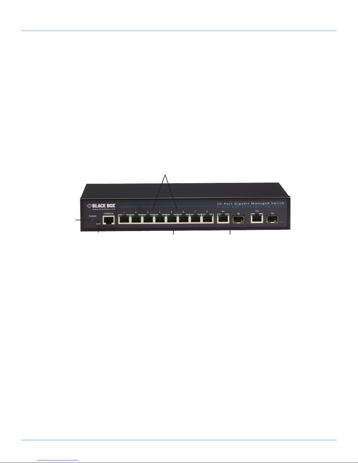
Switch TP LEDs
Power
LED
Reset/
Default
Figure 2-1. Front panel of the 10-Port Gigabit Managed Switch (LGB1108A).
NOTE: The 26- and 48-Port Gigabit Managed Switches’ front panels are similar to the 10-Port Switch. All three switches have the same Power
LED and Reset/Default. The LGB1108A has (8) 10/100/1000BASE-T RJ-45 ports, (2) TP and 100/1G SFP ports, (16) switch TP LEDs, and
(1) RJ-45 console port. The LGB1126A has (20) 10/100/1000BASE-T RJ-45 ports, (4) dual-media UTP/SFP ports, (2) SFP ports, (40) switch
TP LEDs, and (1) RJ-45 console port. The LGB1148A has (44) 10/100/1000BASE-T RJ-45 ports, (4) dual-media UTP/SFP ports, (88) switch
TP LEDs, and (1) DB9 console port.
RJ- 45
console
port
10/100 /1000BA SE-T R J-45 ports
TP and 100/1G SFP ports
2.2. Features
• Switch Architecture: This switch performs a wire-speed, non-blocking switching fabric, which enables wire-speed transport of multiple
packets at low latency on all ports simultaneously. The switch also features full-duplex capability on all ports, which effectively doubles the
bandwidth of each connection. It uses store-and-forward technology to ensure maximum data integrity. With this technology, the entire packet
must be received into a buffer and checked for validity before being forwarded. This prevents errors from being propagated throughout the
network.
• Network Management Options: The switch can also be managed over the network with a Web browser or Telnet application. The switch
includes a built-in network management agent that allows it to be managed in-band using SNMP or RMON (Groups 1, 2, 3, 9) protocols. It
also has an RJ-45 console port connector on the front panel for out-of-band management. A PC may be connected to this port for
configuration and monitoring out-of-band via a null-modem serial cable. (For more information on cabling, see Chapter 9: Cables.)
NOTE: For a detailed description of the management features, refer to the User’s Manual.
Page 8
724-746-5500 | blackbox.com
LGB1108A Quick Start Guide

Chapter 2: Overview
2.3 Description of Hardware
• 1000BASE-T Ports: The switch contains (8), (20), or (44) 1000BASE-T RJ-45 ports. All RJ-45 ports support automatic MDI/
MDI-X operation, autonegotiation, and IEEE 802.3x autonegotiation of flow control, so the optimum data rate and transmission
can be selected automatically.
• SFP Transceiver Slots: The LBG1108A 10-Port Gigabit Managed Switch supports the small form-factor pluggable (SFP) transceiver slots,
which are shared with RJ-45 port 9 and 10. In the default configuration, if an SFP transceiver (purchased separately) is installed in a slot and
has a valid link on the port, the associated RJ-45 port is disabled. The LGB1126A 26-Port Gigabit Managed Switch also supports the small
form-factor pluggable (SFP) transceiver slots, which are shared with RJ-45 ports 21–24, and (2) additional SFP ports. The LGB1148A 48-Port
Gigabit Managed Switch has (4) dual-media UTP/SFP ports (Ports 45–48).
The following table shows a list of transceiver types that have been tested with the switch. For an updated list of vendors supplying these
transceivers, contact your local dealer. For information on the recommended standards for fiber optic cabling, see “1000-Mbps Gigabit
Ethernet Collision Domain” in Section 5.2, Tables 5-1 through 5-4, or contact Tech Support at 724-746-5500.
Table 2-1: Supported SFP Transceivers
Filter Diameter
Media Standard
1000BASE-SX
(Microns) Wavelenth (nm) Maximum Distance*
50 /125
62.5 /125
850 550 m (1804.5 ft.)
850 275 m (902.2 ft.)
9/125
1000BASE-LX/LHX/ XD/ZX
1000BASE-LX Single-Strand
1000BASE-T
100BASE-FX
9/125
9/125
n/a
n/a
n/a
50 /125
62.5 /125
* NOTE: Maximum distance may vary for different SFP vendors.
1310 10 km (6.2 mi.)
1550 30.5 km (19.0 mi.)
130 0 10 km (6.2 mi.)
TX-1310 /RX-155 0 20 km (12.4 mi.)
TX-155 0/ RX-1310 20 km (12.4 mi.)
n.a 100 m (328.1 ft.)
850 2 km (1.2 mi.)
1550 15 km (9.3 mi.)
LGB1108A Quick Start Guide
724-746-5500 | blackbox.com
Page 9
724-746-5500 | blackbox.com
Chapter 2: Overview
• Port and System Status LEDs: The switch includes a display panel for system and port indications that simplify installation and
network troubleshooting. The LEDs are located on the left side of the front panels for easy viewing. Details are shown below and
in Tables 2-2 and 2-3:
Table 2-2: Port Status LEDs
LED Conditions Status
TP (Link/ACT)
TP Speed
SFP (Link/ACT)
Green
Green
Green/Amber
Lit Green when TP link is good; blinks when any
traffic is present.
Lit Green when the TP link is on 1000 Mbps;
Blinks when the TP link is on 100 Mbps;
Off when the TP link is on 10 Mbps.
Lit Green when the SFP link is on 1000 Mbps;
Lit Amber when the SFP link is on 100 Mbps;
Blinks when any traffic is present
Table 2-3: System Status LEDs
LED Conditions Status
Power
Green/OFF
Lit when power is on
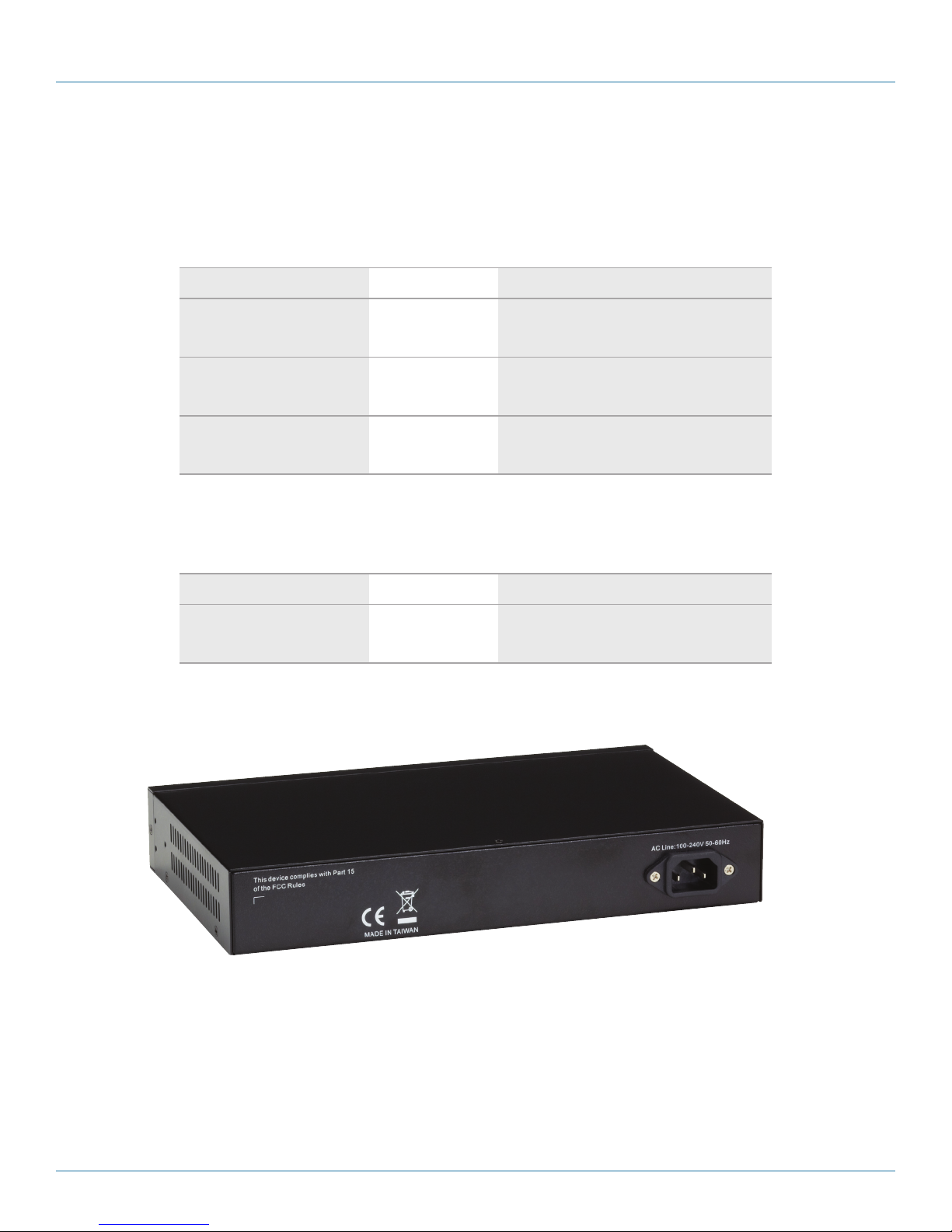
• Power Supply Socket: There is a standard 120-VAC power socket on the rear panel of the switch.
Page 10
Figure 2-2. Back panel.
724-746-5500 | blackbox.com
LGB1108A Quick Start Guide
Chapter 3: Network Planning
3 Network Planning
3.1 Introduction to Switching
A network switch is one of the most important devices for today’s networking technology. It enables simultaneous transmission of multiple
packets, and it can partition a network more efficiently than bridges or routers. When performance bottlenecks are caused by congestion
at the network access point such as a file server, devices can be connected directly to a switched port. And, by using full-duplex mode, the
bandwidth of the dedicated segment can be doubled to maximize throughput.
When networks are based on repeater (hub) technology, the distance between end stations is limited by a maximum hop count. However,
a switch can subdivide the network into smaller and more manageable segments, linking them to the larger network than can turn the hop
count back to zero, removing the limitation.
A switch can be easily configured in any Ethernet, Fast Ethernet, or Gigabit Ethernet network to significantly increase bandwidth while using
conventional cabling and network cards.
3.2 Application Examples
The Gigabit Managed Switch uses (8), (20), or (44) Gigabit Ethernet TP ports with Auto MDI-X and two slots for the
removable SFP module, which supports a number of types of fiber connections, including LC and BiDi-LC modules. It is not only designed to
segment your network, but also to provide a wide range of options in setting up network connections. Some typical applications showing the
10-Port Gigabit Managed Switch (LGB1108A) are described below.
NOTE: The LGB1126A and LGB1148A are similar to the LGB1108A, but have (20) or (44) Gigabit ports. The LGB1126A and LGB1148A also have
dual-media SFP/(10/100/1000) ports, which are described in the specifications section of this manual.
• Remote site application in enterprise or small businesses.
• Peer-to-peer application when used in two remote offices.
• Office network.
• High-performance requirement environment.
• Advanced security for network safety applications.
• Data, voice, and videoconferencing applications.
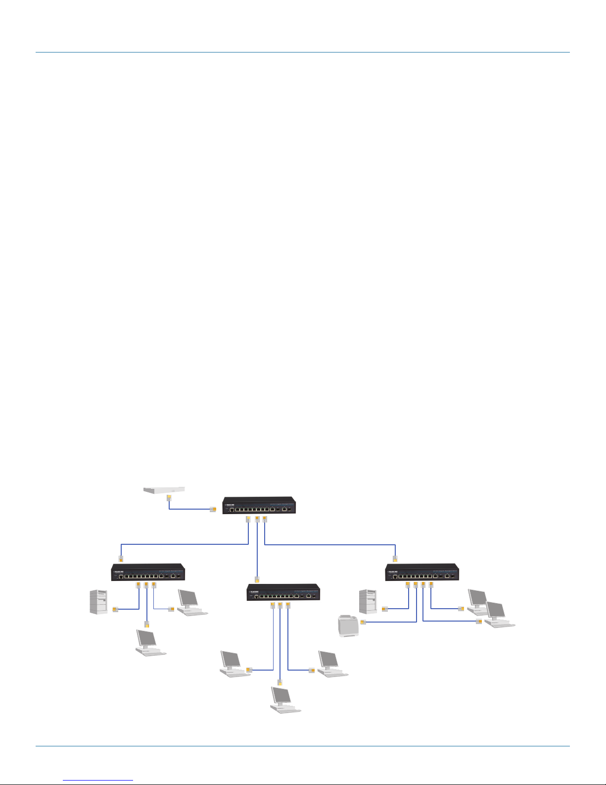
LGB1108A
LGB1108A
LGB1108A
LGB1108A
Figure 3-1. Network connection between remote site and central site.
LGB1108A Quick Start Guide
724-746-5500 | blackbox.com
Page 11
 Loading...