


LB3104A
Black Box LB3104A, LB3124A, LB3804A, LB3135A, LB3824A Configuration Manual
...
1000 Park Drive • Lawrence, PA 15055-1018 • 724-746-5500 • Fax 724-746-0746
© Copyright 1998. Black Box Corporation. All rights reserved.
Order toll-free in the U.S.: Call 877-877-BBOX (outside U.S. call 724-746-5500)
FREE technical support 24 hours a day, 7 days a week: Call 724-746-5500 or fax 724-746-0746
Mailing address: Black Box Corporation, 1000 Park Drive, Lawrence, PA 15055-1018
Web site: www.blackbox.com • E-mail: info@blackbox.com
CUSTOMER
SUPPORT
INFORMATION
AUGUST 1998
LB3104A-AUI-R3 LB3135A-AUI-R3 LB3804A-AUI-R3 LB3835A-AUI-R3
LB3104A-BNC-R3 LB3135A-BNC-R3 LB3804A-BNC-R3 LB3835A-BNC-R3
LB3104A-BT-R3 LB3135A-BT-R3 LB3804A-BT-R3 LB3835A-BT-R3
LB3124A-AUI-R3 LB3136A-AUI-R3 LB3824A-AUI-R3 LB3836A-AUI-R3
LB3124A-BNC-R3 LB3136A-BNC-R3 LB3824A-BNC-R3 LB3836A-BNC-R3
LB3124A-BT-R3 LB3136A-BT-R3 LB3824A-BT-R3 LB3836A-BT-R3
Ethernet Extenders
Configuration Guide
ETHERNET EXTENDER
CONTROL
RESET
READY
POWER
REMOTE
MAIN
LINK
LAN
ERR
Rx
Tx


FCC INFORMATION
1
FEDERAL COMMUNICATIONS COMMISSION
AND
INDUSTRY CANADA
RADIO FREQUENCY INTERFERENCE STATEMENTS
This equipment generates, uses, and can radiate radio-frequency energy, and if not installed and used
properly, that is, in strict accordance with the manufacturer’s instructions, may cause interference to radio
communication. It has been tested and found to comply with the limits for a Class A computing device in
accordance with the specifications in Subpart B of Part 15 of FCC rules, which are designed to provide
reasonable protection against such interference when the equipment is operated in a commercial
environment. Operation of this equipment in a residential area is likely to cause interference, in which
case the user at his own expense will be required to take whatever measures may be necessary to correct
the interference.
Changes or modifications not expressly approved by the party responsible for compliance could void the user’s
authority to operate the equipment.
This digital apparatus does not exceed the Class A limits for radio noise emission from digital apparatus set out in the Radio
Interference Regulation of Industry Canada.
Le présent appareil numérique n’émet pas de bruits radioélectriques dépassant les limites applicables aux appareils numériques
de la classe A prescrites dans le Règlement sur le brouillage radioélectrique publié par Industrie Canada.

ETHERNET EXTENDERS—CONFIGURATION GUIDE
2
INSTRUCCIONES DE SEGURIDAD (Normas Oficiales Mexicanas Electrical Safety Statement)
1. Todas las instrucciones de seguridad y operación deberán ser leídas antes de que el aparato eléctrico sea operado.
2. Las instrucciones de seguridad y operación deberán ser guardadas para referencia futura.
3. Todas las advertencias en el aparato eléctrico y en sus instrucciones de operación deben ser respetadas.
4. Todas las instrucciones de operación y uso deben ser seguidas.
5. El aparato eléctrico no deberá ser usado cerca del agua—por ejemplo, cerca de la tina de baño, lavabo, sótano
mojado o cerca de una alberca, etc..
6. El aparato eléctrico debe ser usado únicamente con carritos o pedestales que sean recomendados por el fabricante.
7. El aparato eléctrico debe ser montado a la pared o al techo sólo como sea recomendado por el fabricante.
8. Servicio—El usuario no debe intentar dar servicio al equipo eléctrico más allá a lo descrito en las instrucciones de
operación. Todo otro servicio deberá ser referido a personal de servicio calificado.
9. El aparato eléctrico debe ser situado de tal manera que su posición no interfiera su uso. La colocación del aparato
eléctrico sobre una cama, sofá, alfombra o superficie similar puede bloquea la ventilación, no se debe colocar en
libreros o gabinetes que impidan el flujo de aire por los orificios de ventilación.
10. El equipo eléctrico deber ser situado fuera del alcance de fuentes de calor como radiadores, registros de calor, estufas
u otros aparatos (incluyendo amplificadores) que producen calor.
11. El aparato eléctrico deberá ser connectado a una fuente de poder sólo del tipo descrito en el instructivo de
operación, o como se indique en el aparato.
12. Precaución debe ser tomada de tal manera que la tierra fisica y la polarización del equipo no sea eliminada.
13. Los cables de la fuente de poder deben ser guiados de tal manera que no sean pisados ni pellizcados por objetos
colocados sobre o contra ellos, poniendo particular atención a los contactos y receptáculos donde salen del aparato.
14. El equipo eléctrico debe ser limpiado únicamente de acuerdo a las recomendaciones del fabricante.
15. En caso de existir, una antena externa deberá ser localizada lejos de las lineas de energia.
16. El cable de corriente deberá ser desconectado del cuando el equipo no sea usado por un largo periodo de tiempo.
17. Cuidado debe ser tomado de tal manera que objectos liquidos no sean derramados sobre la cubierta u orificios de
ventilación.
18. Servicio por personal calificado deberá ser provisto cuando:
A: El cable de poder o el contacto ha sido dañado; u
B: Objectos han caído o líquido ha sido derramado dentro del aparato; o
C: El aparato ha sido expuesto a la lluvia; o
D: El aparato parece no operar normalmente o muestra un cambio en su desempeño; o
E: El aparato ha sido tirado o su cubierta ha sido dañada.

TRADEMARKS USED AND TELECOMMUNICATION SAFETY
3
TRADEMARKS USED IN THIS MANUAL
Any trademarks mentioned in this manual are acknowledged to be the property of the trademark owners.
Telecommunication Safety
The safety status of each of the ports on the Ethernet Extender is declared according to EN 41003 and is
detailed in the table below:
Safety Status Ports
SELV V.24, V.35, V.36, LAN
TNV-1 4W
SELV = Safety Extra-Low Voltage
TNV-1 = Telecommunications Network Voltage within the limits of SELV and subject to overvoltages

ETHERNET EXTENDERS—CONFIGURATION GUIDE
4
Contents
Chapter Page
1. Introduction ............................................................................................................................................................6
1.1 A General Description ............................................................................................................................6
1.2 How “Single IP” Address Translation Works ..........................................................................................7
1.2.1 What Single IP Does ..........................................................................................................................7
1.2.2 The Benefits of Single IP....................................................................................................................8
1.3 Solid Firewall ............................................................................................................................................9
1.4 Ethernet Extender Features ....................................................................................................................9
1.5 Ethernet Extender Applications ..........................................................................................................11
1.5.1 Bridging ............................................................................................................................................11
1.5.2 4-Wire Modem ..................................................................................................................................11
1.5.3 Single IP ............................................................................................................................................12
2. Configuration Introduction ..................................................................................................................................13
2.1 How to Start Configuring the Ethernet Extender ..............................................................................13
2.1.1 Connecting to the Internet/Intranet as a Public IP Net ..............................................................13
2.1.2 Connecting to the Internet/Intranet as a Private IP Net (Using Single IP)................................14
2.2 Initial Setup ............................................................................................................................................15
2.2.1 Connecting to the Terminal ............................................................................................................15
2.2.2 Setting a Password ............................................................................................................................16
2.2.3 Changing and Deleting the Password ............................................................................................16
2.3 The Quick Setup Menu ........................................................................................................................17
2.4 Menus and Screens ................................................................................................................................17
2.4.1 The Main Menu ................................................................................................................................17
2.4.2 Quick Setup ......................................................................................................................................17
2.4.3 Security Setup ..................................................................................................................................17
2.4.4 Advanced Menu ................................................................................................................................18
2.4.5 View....................................................................................................................................................18
2.4.6 Diagnostic Tools................................................................................................................................18
2.4.7 Exit ....................................................................................................................................................18
3. Quick Setup Menu ................................................................................................................................................19
3.1 Quick Setup Menu Parameters ............................................................................................................19
3.1.1 Link Mode ........................................................................................................................................21
3.1.2 Routing ..............................................................................................................................................21
3.1.3 Connection........................................................................................................................................21
3.1.4 WAN IP Address................................................................................................................................21
3.1.5 BOOTP Address................................................................................................................................21
3.1.6 Modem Type ....................................................................................................................................21
3.1.7 Baud Rate ..........................................................................................................................................21
3.1.8 Host IP Setup ....................................................................................................................................22
3.1.9 Security Setup ..................................................................................................................................23
3.2 Where To Go From Here ......................................................................................................................24

CONTENTS
5
Chapter Page
4. Security Setup Menu..............................................................................................................................................25
4.1 Enabling TELNET Access......................................................................................................................26
4.2 Enabling SNMP Access ..........................................................................................................................27
4.3 Enabling/Disabling the Solid Firewall ................................................................................................28
5. Advanced Setup Menu ..........................................................................................................................................30
5.1 Advanced Menu and Setup Menu ........................................................................................................30
5.2 Device Control Menu ............................................................................................................................79
5.3 List of Operations ..................................................................................................................................85
Appendix A: Important ISDN Issues (For U.S. Users Only)....................................................................................89
A.1 Which ISDN Service Should You Order? ............................................................................................89
A.2 Ordering ISDN ......................................................................................................................................89
A.3 Provisioning ISDN..................................................................................................................................89
A.4 ISDN Parameters ....................................................................................................................................89
Appendix B: BOOT Manager ....................................................................................................................................92
B.1 Preface ....................................................................................................................................................92
B.2 Accessing BOOT Manager ....................................................................................................................92
B.2.1 Access via Software Download Menu ..............................................................................................92
B.2.2 Rescue................................................................................................................................................93
B.3 The BOOT Manager Menu ..................................................................................................................93
B.3.1 Load New Software ..........................................................................................................................94
B.3.2 Partitions Status ................................................................................................................................94
B.3.3 Run Second Partition ......................................................................................................................94
B.3.4 Reactivate Second Partition ............................................................................................................95
B.3.5 Duplicate First Partition ..................................................................................................................95
B.3.6 Erase Configuration..........................................................................................................................95
B.3.7 Erase All FLASH ..............................................................................................................................95
B.3.8 Set Baud Rate ....................................................................................................................................95
B.3.9 Exit ....................................................................................................................................................96

ETHERNET EXTENDERS—CONFIGURATION GUIDE
6
1. Introduction
Ethernet Extenders can be used for various bridging and routing functions, and can connect an Ethernet or
Token Ring LAN to the Internet or Intranet via ISDN, Frame Relay, asynchronous or synchronous dialup, or
Digital Data Service (DDS) links operating at data rates up to 1.5 Mbps.
This manual gives a general introduction to the Ethernet Extender and describes how to configure it. For
information about the physical features or installing Ethernet Extenders, refer to the Ethernet Extender
Installation and Operation Guide.
1.1 A General Description
Ethernet Extenders are standalone bridges and IP/IPX routers for the small office. Quick setup and advanced
configuration menus provide on-screen instructions that guide you through the configuration procedures.
The Ethernet Extender features:
• Bridging.
• IP Routing.
• IPX Routing.
• Address Translation.
• Firewall.
Bridging
The Ethernet Extender supports standard bridging functions. Because bridging is the Ethernet Extender’s
default, you can use the Ethernet Extender as a bridge with little or no configuration.
IP Routing
The Ethernet Extender is an IP router that supports:
• Static IP net configuration.
• Dynamic IP net learning using the RIP and RIP-2 protocols.
• CIDR topologies.
• Multiple IP nets on the LAN or WAN interfaces.
• Numbered and unnumbered I/F.
• IP fragmentation.
IPX Routing
In addition to IP routing, the Ethernet Extender also supports standard IPX routing and includes support for
RIP and SAP.
CHAPTER 1: Introduction
7
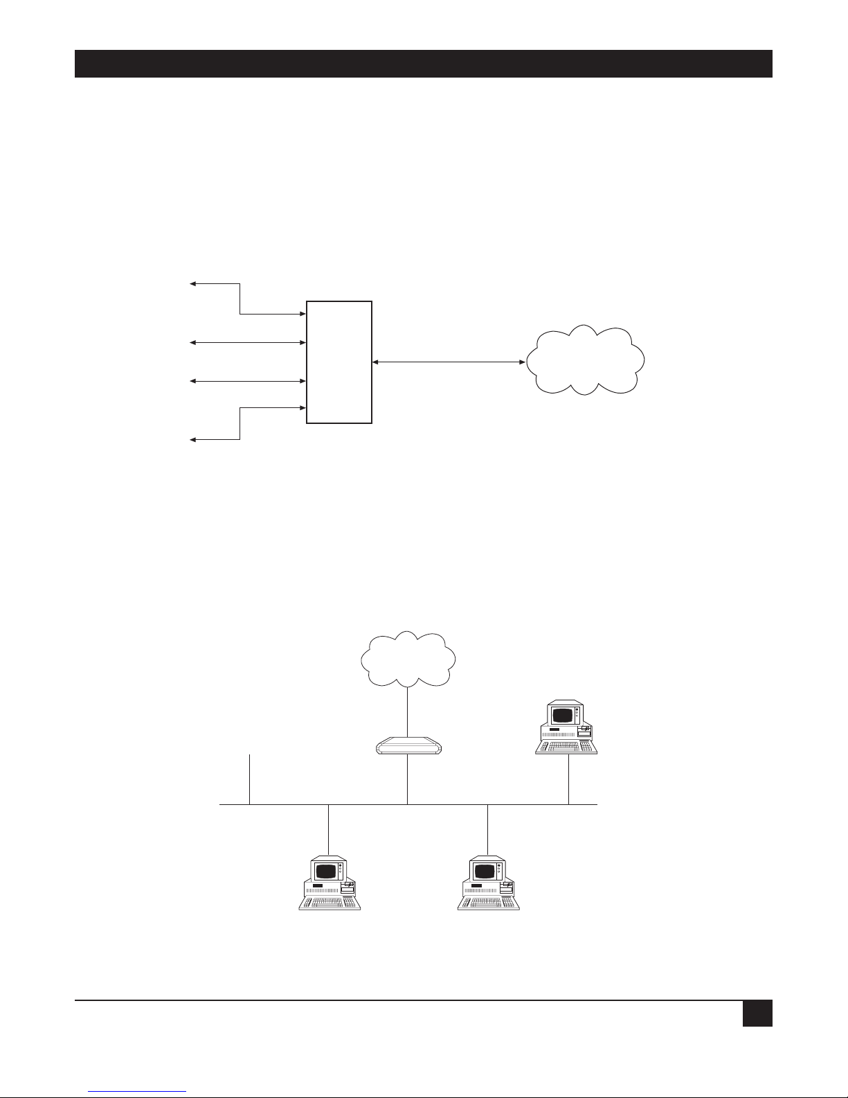
1.2 How “Single IP” Address Translation Works
Single IP allows users in a small-office LAN to connect to the Internet/Intranet quickly and transparently with
just one assigned IP address.
1.2.1 W
HAT SINGLE IP DOES
Single IP is an Ethernet Extender feature that translates multiple IP addresses on a small-office LAN to one
single IP address on the Internet.
Figure 1-1. IP connection to the Ethernet Extender.
Normally, a LAN requires a complete statically assigned, unique and legal subnet, with one IP address for every
station, in order to connect to the Internet or Intranet. Single IP allows an entire small office to connect to the
Internet or corporate intranet using only one dynamically or statically assigned IP address received from the
ISP via a dial-up modem, ISDN connection, leased line, DDS, or Frame Relay line.
Figure 1-2. Ethernet Extender with Single IP enabled.
Small Office
Ethernet
Ethernet Extender
Internet (ISP)
or Intranet
IP
1
IP
2
IP
3
IP
4
Ethernet
Extender
Single IP
IP
Internet/Intranet
ETHERNET EXTENDERS—CONFIGURATION GUIDE
8
Configure the Ethernet Extender to dial an Internet/Intranet Access Router and to supply a user name and
password over PPP. The Internet/Intranet Access Router automatically supplies the Ethernet Extender with a
single temporary IP address using the IPCP protocol—the same way that a single PC would connect directly to
the ISP.
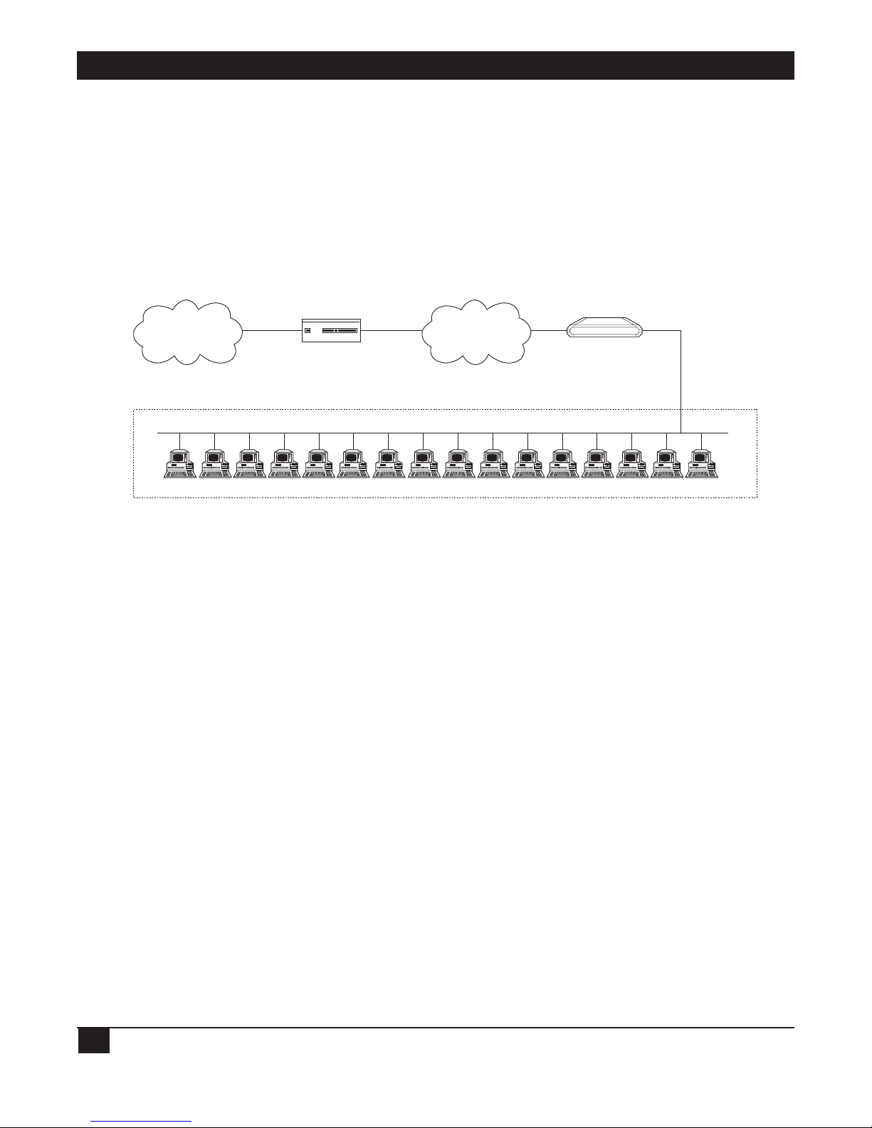
You can connect a complete small-office LAN with a private subnet to the Ethernet Extender. Through the
Ethernet Extender you can access the Internet/Intranet. The Internet/Intranet provider does not need to
specially coordinate with the office or allocate subnets.
Figure 1-3. Ethernet Extender in Single IP Mode.
1.2.2 T
HE BENEFITS OF SINGLE IP
• Allows a small office to connect to the Internet/Intranet in the same way as a single PC.
• Requires only one legal IP address.
• Obtains a single legal IP address from the Internet/Intranet Access Router using standard IPCP.
• Allows a small office to access any public IP subnet.
• Allows Web browsing, FTP, Telnet, e-mail, news and other IP applications using any TCP/IP stack on any
type of station in the small office.
• Provides security against Internet hackers using the Solid Firewall feature.
• Allows automatic connection and disconnection of the link based on actual or specific use of the
Internet/Intranet.
• Allows filtering of traffic on the link to reduce waste of bandwidth and to improve security.
Private Subnet 192.168.1.
RFC 1918
16 potential users
3 concurrent users (.4, .11, .14)
Ethernet Extender
(Single IP feature enabled)
192.168.1.1.
Ethernet Extender
ISDN
FR
PSTN
Leased Line
Central Access
Router
Internet/Intranet

CHAPTER 1: Introduction
9
IP Applications: Web Browsing, FTP, Telnet, E-mail, News and Others
Single IP allows the use of any Web browser, such as Netscape or Internet Explorer, to access the World-Wide
Web. Refer to the list below for some of the types of Internet and Intranet access supported by Single IP:
• World Wide Web browsing.
• E-mail.
• FTP client.
• News reader.
• Telnet client.
• Ping (outbound).
Single IP supports any SOCKS-compatible client application (for example, Netscape). Access to FTP within
Netscape, Gopher access, and access to secure servers is also supported. POP3 clients (for example, Eudora,
Pegasus mail, Microsoft Exchange) and other e-mail packages and news readers are allowed access to e-mail
servers through Single IP e-mail support.
Single IP allows use of FTP client applications that support the username@hostname method of firewall
crossing; for example, WS_FTP, CuteFTP, and command-line FTP clients. Connection through another firewall
using the same mechanism is also allowed.
1.3 Solid Firewall
The Solid Firewall feature prevents access from the Internet/Intranet into the small-office LAN. This feature
makes the small-office LAN invisible to outside users. The Solid Firewall feature is a simple and foolproof way of
protecting security sensitive small offices (for example, doctors and lawyers) from Internet hackers. Refer to
Chapter 4 for more information about the Firewall.
1.4 Ethernet Extender Features
• Supports bridging.
• Supports IP, IPX, and IP+IPX routing.
• Supports Single IP feature (IP Address Translation) which allows a user to connect to the Internet/Intranet.
• Supports static nets and multi-nets. Refer to Chapter 5.
• Supports IP fragmentation. Refer to Chapter 5.
• PPP multi-link support enables maximum utilization of ISDN lines. Refer to Chapter 5.
• Supports bandwidth on demand (BOD). Refer to Chapter 5.
• Integral Frame Relay operating at data rates up to T1. Refer to Chapter 5.
• Supports 4-wire, asynchronous, synchronous, ISDN and CSU/DSU WAN interfaces.
• Supports Token Ring, 10BASE2, 10BASE5, or 10BASE-T LAN interface.

ETHERNET EXTENDERS—CONFIGURATION GUIDE
10
• Supports backup links for bridge and router links.
• Supports TELNET, allowing configuration and control of the device over WAN and LAN. Refer to
Chapter 3.
• Supports RADIUS. Refer to Chapter 5.
• Fast configuration can be performed from a terminal emulator, and via TELNET. Refer to Chapter 3.
• An SNMP agent provides management by any standard SNMP management station. Refer to Chapter 5.
• Software downloading is available using XMODEM or TFTP. Refer to Chapter 5.
• Dual-image flash enables downloading two software versions. Refer to Chapter 5.
• Independent ISDN code downloading is available using XMODEM. Refer to Chapter 5.
• Indicates ISDN link integrity. Refer to Chapter 5.
• Connection on Demand feature reduces WAN costs. Refer to Chapter 5.
• PAP/CHAP provides access authentication. Refer to Chapter 5.
• Solid Firewall feature allows the user to block all access from the outside into the LAN. Refer to Chapter 4.
• Undesired access to Ethernet Extender via TELNET or SNMP can also be blocked or password-protected.
Refer to Chapter 4.

CHAPTER 1: Introduction
11
1.5 Ethernet Extender Applications
The Ethernet Extender can be used in a large variety of applications. Some examples follow.
1.5.1 B
RIDGING
Two Ethernet Extenders can be used opposite each other in a standard bridging application. The Ethernet
Extender connected to the larger network or to a network with connections to other networks, is the Main
Ethernet Extender. The Ethernet Extender connected to the smaller network is the Remote Ethernet Extender.
Refer to Figure 1-4.
Figure 1-4. Standard Bridging Application.
1.5.2 4-W
IRE MODEM
The Ethernet Extender has a built-in 4-wire modem and can be used for one or more PCs to connect to each
other or to the Internet. Refer to Figure 1-5.
Figure 1-5. Connecting to the Ethernet Extender via a 4-Wire Modem.
4-Wire Modem
4-Wire Modem
Ethernet Extender
PC
Internet
Internet
Router
Ethernet Extender
Ethernet Extender
Remote
Main
ETHERNET EXTENDERS—CONFIGURATION GUIDE
12
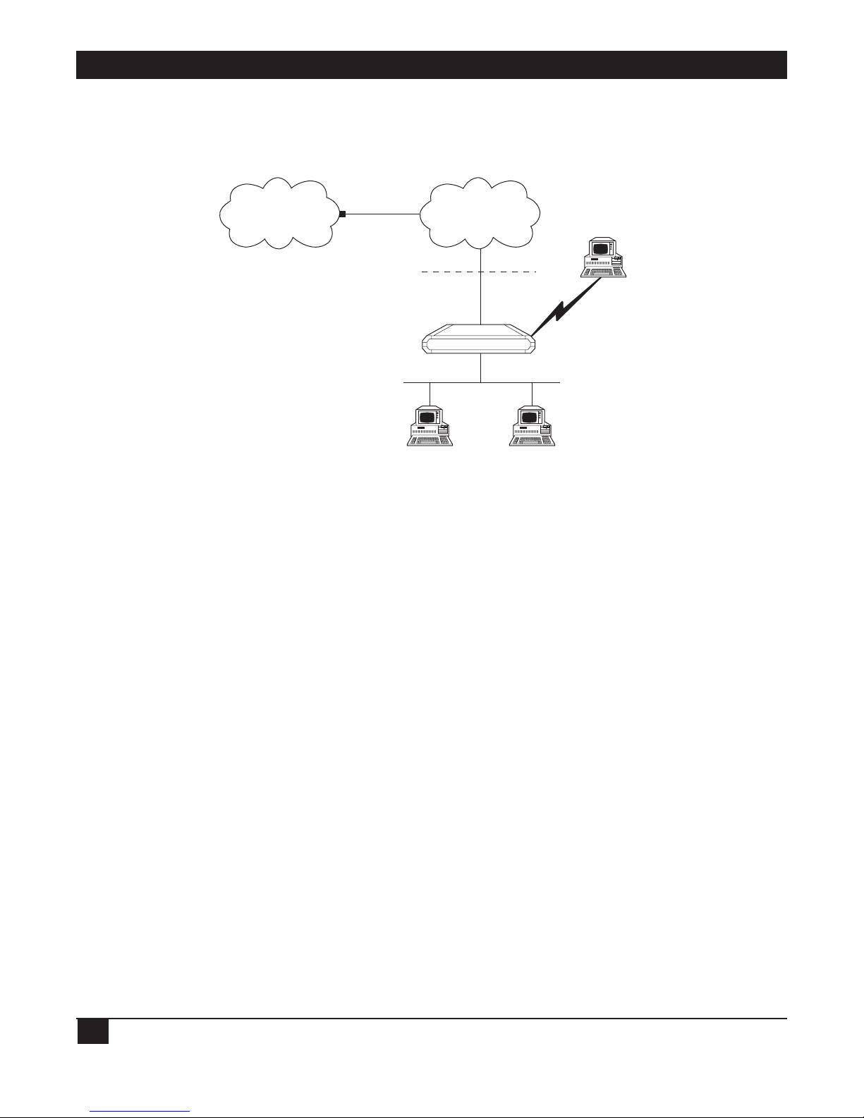
1.5.3 SINGLE IP
The Ethernet Extender can be used as a point of presence on the Internet. A home user can dial in to the
Ethernet Extender, and use the Ethernet Extender Single IP feature to access the Internet. Refer to Figure 1-6.
Figure 1-6. Ethernet Extender Using Single IP.
Internet
ISP
WAN
Home User
Solid Firewall
Single IP Enabled
Ethernet Extender

CHAPTER 2: Configuration Introduction
13
2. Configuration Introduction
2.1 How to Start Configuring the Ethernet Extender
The Ethernet Extender can be configured as either a bridge or a router. By default, it’s configured in bridge
mode. Decide whether the Ethernet Extender will be used as a bridge or a router before you start the
configuration.
Before you configure the Ethernet Extender as a bridge, set the location switch to Remote or Main. One of the
two Ethernet Extenders in the bridge must have the location switch set to Remote and the other set to Main:
• Remote—If the Ethernet Extender you are configuring as a bridge is connected to the network that is
smaller, and has no connections via a router to other networks.
• Main—If the Ethernet Extender you are configuring as a bridge is connected to the network that is larger
or has connections via a router to other networks.
For more information, refer to the Ethernet Extender Installation and Operation Guide.
Before you configure the Ethernet Extender as a router, follow the appropriate checklists, listed below.
NOTE
If you are using the Ethernet Extender as a router, set the location switch to Main. For
more information, refer to the Ethernet Extender Installation and Operation Guide.
2.1.1 CONNECTING TO THE INTERNET/INTRANET AS A PUBLIC IP NET
Use the following check list to make sure you are ready to connect to the Internet/Intranet.
Internet Check List
• Subscribe to the Internet Service Provider (ISP) and request a static IP subnet.
• Request a dialup telephone number, your username, and your password from the ISP. Configure this into
the Ethernet Extender using the Quick Setup option. Check whether a login script is necessary to access the
ISP. If it is, call Technical Support.
• Disable the Single IP in the Ethernet Extender Quick Setup option.
• Make sure the line (ISDN, PSTN, Frame Relay, or DDS) to the ISP is working properly.
• Use the static IP subnet you have obtained to configure the LAN IP host addresses of the Ethernet
Extender.

ETHERNET EXTENDERS—CONFIGURATION GUIDE
14
Preparing Your PCs
• Make sure your PCs have a correctly installed TCP/IP stack such as WinSock or Chameleon.
• Assign an IP address from the static IP subnet to each PC.
• Make sure that each PC has the correct subnet mask.
• Configure each PC with the Ethernet Extender as the Default Gateway.
• Configure each PC with the ISP’s DNS IP address.
• Check that your small-office LAN is correctly set up to work with IP.
2.1.2 C
ONNECTING TO THE INTERNET/INTRANET AS A PRIVATE IP NET (USING SINGLE IP)
Use the following checklist to make sure you are ready to connect to the Internet/Intranet.
Internet Check list
• Subscribe to the Internet Service Provider (ISP) and request a single subscription connection.
• Decide on a private IP net for your small-office LAN (Reference RFC 1918).
• Request a dialup telephone number, your username, and your password from the ISP. Configure this into
the Ethernet Extender using the Quick Setup option. Check whether a login script is necessary to access the
ISP. If it is, call Technical Support.
• Enable the Single IP in the Ethernet Extender Setup option.
• Make sure the line (ISDN, PSTN, Frame Relay, or DDS) to the ISP is working properly.
• Use the private IP subnet you have obtained to configure the private host addresses of the Ethernet
Extender.
• Check that your small-office LAN is correctly set up to work with IP.
Preparing your PCs
• Make sure your PCs have a correctly installed TCP/IP stack such as WinSock or Chameleon.
• Assign an IP address, unique to the LAN, to each PC.
• Configure each PC with the Ethernet Extender as the Default Gateway.
• Make sure that each PC has a correct subnet mask.
• Configure each PC with the ISP’s DNS IP address.
• Check that your small-office LAN is correctly set up to work with IP.
CHAPTER 2: Configuration Introduction
15
2.2 Initial Setup
The Ethernet Extender features a setup program that is invoked and run from an ASCII terminal or a PC
terminal emulator. The terminal/terminal-emulator is connected to the CONTROL port on the Ethernet
Extender’s front panel.
This section describes the procedures necessary to connect to the terminal and to access the setup program’s
Main menu.
2.2.1 C
ONNECTING TO THE TERMINAL
To connect the terminal:
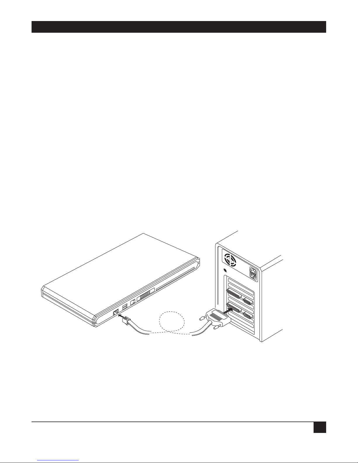
1. Connect a control cable between the Ethernet Extender RJ-45 CONTROL port and the connector on the
terminal; or between the Ethernet Extender RJ-45 CONTROL port and the PC communication port (refer
to Figure 2-1).
2. Set the terminal to work at any baud rate from 2.4 to 19.2 kbps, no parity, 8 data bits. The baud rate is selfadaptable.
3. Set the hardware control to OFF.
4. Switch on the Ethernet Extender. The operational status screen appears. Press ENTER several times to
invoke the password message.
Figure2-1. Connecting to the Terminal.

ETHERNET EXTENDERS—CONFIGURATION GUIDE
16
2.2.2 SETTING A PASSWORD
For first-time operation, or if no configuration password has been specified, the following message appears:
WARNING: No configuration password exists.
Define configuration password? (Y/N):
To set a password:
1. Type Y to set a configuration password. A message appears, prompting you to enter a new configuration
password.
2. Type a password. The password can be up to twelve characters. Press the ENTER key. A message appears,
prompting you to retype the password for verification.
3. Re-type the password and press ENTER. The Main menu screen appears.
The password protects entry to the configuration module, preventing unauthorized personnel from
changing setup and configuration parameters.
NOTE
All Ethernet Extender password-verification routines are case-sensitive. Once a
password has been set, always use the same case as in the original when typing the
password. (For example, “password” and “Password” are two different passwords.)
2.2.3 CHANGING AND DELETING THE PASSWORD
To change the password during normal operation:
1. From the Main menu, select option 0, Exit, to return to the Operational Status Messages screen.
2. Press ENTER several times. You will be prompted to enter the current password.
3. Enter the current password. A message appears, asking if you want to update the current password. Type Y.
You will be prompted to re-enter the current password.
4. Re-enter the current password. A message appears prompting you to enter the new password.
5. Enter the new password, and re-enter the same password for verification. The Main menu appears.
To delete the current password:
1. Follow steps 1-5 above to change the password. When prompted to enter a new password, press ENTER
without typing a new password. This deletes the current password and removes password protection.
2. Press ENTER again when prompted for verification. The Main menu appears. If the unit doesn’t have an IP
Address, the Quick Setup menu appears.
NOTE
Use of password protection for the configuration module is recommended. Always use
the “Exit” option in the Main menu once the unit has been configured. Using the Exit
option will force personnel requiring access to the configuration module to use the
password.

CHAPTER 2: Configuration Introduction
17
2.3 The Quick Setup Menu
The Quick Setup menu is used to define the basic parameters for your Ethernet Extender. The Quick Setup
menu allows you to adjust setup and link configuration parameters while the Ethernet Extender is in operation.
The line-by-line prompting guides you throughout the procedure. On-screen instructions and explanations
guide you through the setup procedure.
The parameters include:
• IP Parameters.
• WAN Interface.
• Security (Password) Setup.
For a complete description of the Quick Setup menu, refer to Chapter 3.
2.4 Menus and Screens
This section provides a brief description of the available Ethernet Extender menus and screens.
2.4.1 T
HE MAIN MENU
The name of the device (Ethernet Extender) connected to the terminal is listed at the top of the screen. The
Main menu has five options. To choose an option, you type the number preceding the option.
MAIN MENU ( Device name - Name )
—————
1. Quick setup
2. Security setup
3. Advanced setup
4. View
5. Diagnostic tools
0. Exit
Figure 2-2. Ethernet Extender Main Screen.
2.4.2 Q
UICK SETUP
The Quick Setup menu allows you to adjust setup and link configuration parameters while the Ethernet
Extender is in operation. Line-by-line prompting simplifies the setup. On-screen instructions and explanations
guide you through the setup procedure.
2.4.3 S
ECURITY SETUP
Use the options in the Security Setup menu to control Ethernet Extender management and entry to your LAN
by unauthorized users.

ETHERNET EXTENDERS—CONFIGURATION GUIDE
18
2.4.4 ADVANCED MENU
The Advanced menu lists Ethernet Extender configuration parameters and their current values. You can
change these parameters and perform advanced configuration operations not available through the Quick
Setup menu. Resetting the device and software downloads are also performed via the Advanced menu.
2.4.5 V
IEW
Use the options in the View menu to view configuration screens and information on interface connections,
routing tables, and statistics.
2.4.6 D
IAGNOSTIC TOOLS
Use the Diagnostic Tools menu to verify WAN and LAN connectivity. The Ping feature allows you to dial (Ping)
another user on the LAN or WAN. If the remote user replies, WAN connectivity is confirmed up to and
including the IP level.
2.4.7 E
XIT
Select this option to return to the Operational Status Messages screen. From the Operational Status Messages
screen, you can remove or change the password.

CHAPTER 3: Quick Setup Menu
19
3. Quick Setup Menu
The Quick Setup menu allows you to enter the minimum number of parameters needed to operate your
Ethernet Extender. You can access the Quick Setup menu via:
• ASCII terminal.
• Telnet.
For more extensive control of your Ethernet Extender, refer to Chapters 4 and 5.
3.1 Quick Setup Menu Parameters
The Quick Setup screen guides you through the configuration, port by port. The Quick Setup screen asks you
for the appropriate parameters depending on the type of port you are configuring and how you have already
configured other ports.
• To accept the current parameter, press ENTER.
• The parameter options are enclosed in brackets [ ]. To view the options, toggle with the space bar and press
ENTER.
• To enter new information, type in the new parameters and press ENTER.
After all parameters have been accepted or changed, you can view them on the screen. A confirmation message
appears requesting that you confirm all the setup changes. The device resets after the changes are saved.
To configure the setup parameters:
1. From the Main menu, select option 1, Quick Setup.
2. Follow the on-screen instructions to accept or modify the setup parameters.
3. Press Y to save the setup parameters.

ETHERNET EXTENDERS—CONFIGURATION GUIDE
20
QUICK SETUP
—————WARNING: This device automatically exits to Operational Messages
10 minutes after last keyboard action without saving parameters
‘ENTER’ - Accept parameter , ‘SPACE’ - Change parameter .
WAN interface #1 - V.35
Connection type: [Uplink ]
Link mode: [Synchronous ]
Routing: [BRIDGE ], Protocol: [PROPRIETARY]
Connection : [Always ]
WAN interface #2 - V.24
Connection type: [Answer ]
Link mode: [Asynchronous ]
Routing: [IP ROUTER ], Protocol: [SLIP ]
WAN IP address: 0.0.0.0 , enter new : 0.0.0.0
BOOTP address: 0.0.0.0 , enter new :0.0.0.0
Modem type: Direct Connection
Do you want to change modem type (Y/N)? : [N] Baud rate: [57.6 ] Kbps
Host IP setup:
LAN IP address : 192.168.218.1 , enter new : 192.168.218.1
LAN IP mask : 255.255.255.000 , enter new : 255.255.255.000
Default gateway setting by: [Interface ]
Default gateway interface: 1
SECURITY setup
Device access name : Ethernet Extender
No password at present - do you want to create password (Y/N)? : [N]
Security type: [Disabled]
Saving the changes might cause RESET the unit.
Do you want to save QUICK SETUP (Y/N) ? Y
Figure 3-1.Quick Setup Example.

CHAPTER 3: Quick Setup Menu
21
The fields in the Quick Setup example are described below:
3.1.1 L
INK MODE
Select this parameter to determine how data is transmitted across the link. There are three modes:
1. When the mode is synchronous, data bits are transmitted at a fixed rate. The sender and the receiver are
synchronized.
2. When the mode is asynchronous, data units are transmitted character-by-character. The characters are
preceded by start bits and followed by stop bits. The start and stop bits provide synchronization at the receiver
side.
3. Frame Relay is a packet-switching protocol for connecting devices on a WAN.
Use the space bar to switch to synchronous, asynchronous, or Frame Relay mode.
3.1.2 R
OUTING
Select this parameter to assign the link type. Use the space bar to switch to Bridge, IP, IPX, or IP & IPX.
Selecting IPX link type disables the Single IP and WAN IP Address features, and eliminates the corresponding
parameters from the screen.
3.1.3 C
ONNECTION
Select this parameter to determine when the link between the local LAN and the Internet should be activated.
Selecting upon traffic to WAN activates the link only when there is traffic to be sent on the link. Selecting
always keeps the link active independent of traffic. If you pay for your connection by the minute, selecting upon
traffic to WAN will reduce your operating costs.
Choose always or upon traffic to WAN. If you choose upon traffic to WAN, the Disconnect Timeout parameter
displays.
3.1.4 WAN IP A
DDRESS
Select this parameter to enter the IP address for the WAN interface.
3.1.5 BOOTP A
DDRESS
Select this parameter to enter the IP address for the BOOTP server.
3.1.6 M
ODEM TYPE
Select this parameter to change the modem type.
3.1.7 B
AUD RATE
Select this parameter to display the rate at which data is sent between the Ethernet Extender and the modem.
Use the space bar to run through the different baud rates. The Quick Setup default value is recommended for
your modem.

ETHERNET EXTENDERS—CONFIGURATION GUIDE
22
Figure 3-2. Setting Baud Rate.
3.1.8 H
OST IP SETUP
LAN IP Address
Select this parameter to enter the IP address. Every device on a TCP/IP network must have an address to
identify it. The IP address is a value consisting of the network address and the host address on that network.
The value assigned to a network depends on the number of computers on that network.
The IP address is a 32-bit number. The number is made up of 4 parts, with each part consisting of 3 digits. One
part of the address identifies the network and another part of the address identifies the host. Which numbers in
the address identifies the host is dependent of the class.
There are 5 classes of IP addresses. Each class represents a network having a certain number of computers. For
example, a Class C address is given to a network having from 1 to 255 computers. Table 3-1 gives the ranges for
different classes of IP addresses.
Table 3-1. IP Classes
Class Range
A 0.0.0.0 to 127.255.255.255
B 128.0.0.0 to 191.255.255.255
C 192.0.0.0 to 223.255.255.255
D 224.0.0.0 to 239.255.255.255
E 240.0.0.0 to 247.255.255.255
The numbers in each part of the code is translated into binary. The binary code identifies the network and the
host.
IP addresses are assigned by the Internet Network Information Center (InterNIC). InterNIC assigns the
network ID. Host IDs are assigned by the network administrator.
Public Access Service
Modem
28.8 kbps
baud rate
V.24
Ethernet Extender
CHAPTER 3: Quick Setup Menu
23
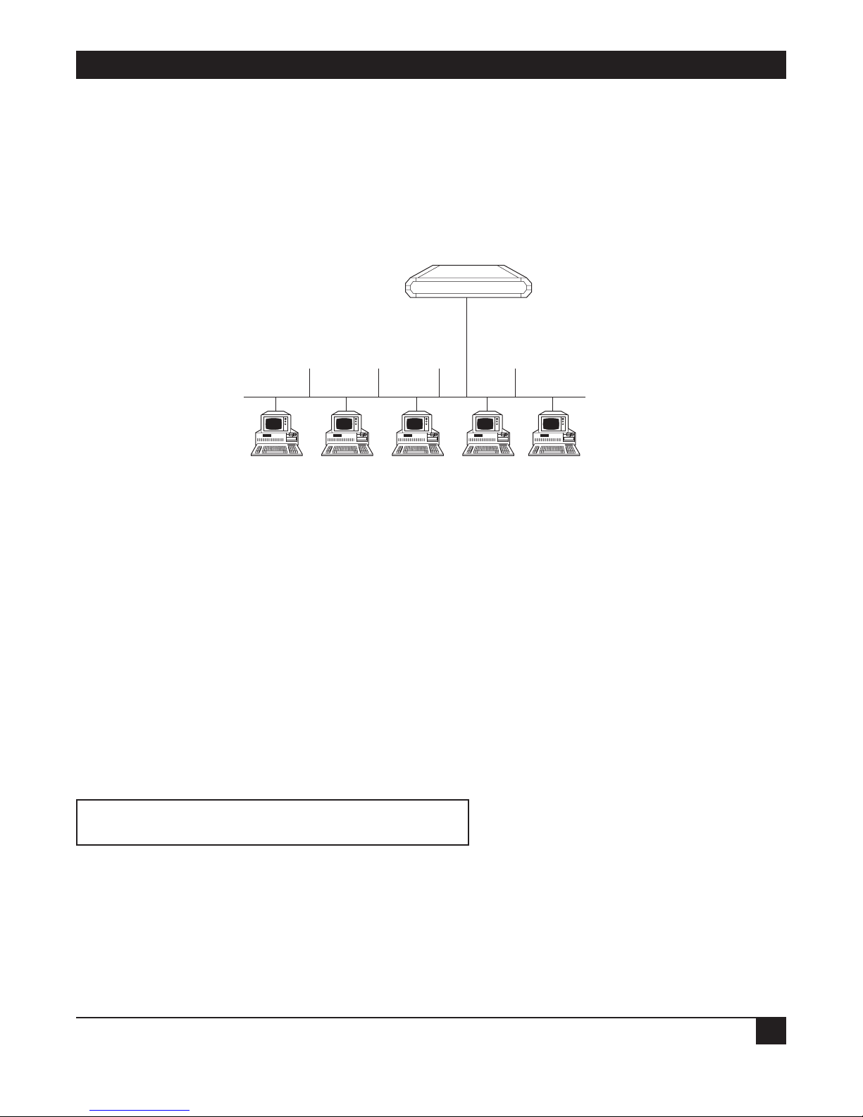
LAN IP Mask
Select this parameter to enter the IP mask. The mask is configured automatically from the IP address class. If
you want to change the default mask, enter a new mask. For example, the IP mask is usually 225.225.225.0. A
mask of this sort would allow 254 hosts on the LAN. If you want to create a subnet which allows 6 users,
including the Ethernet Extender, configure the mask as 22.225.225.248. on the Ethernet Extender and each
host that is included on the subnet. Refer to Figure 3-3.
Figure 3-3. Setting up the IP Mask.
3.1.9 SECURITY SETUP
Device Access Name
Select this parameter to display the name assigned to the Ethernet Extender for identification by the Internet
service provider. To change the device access name, type in the new name and press ENTER.
Device Access Password
Select this parameter to assign or update a password. The password is used to access the Internet.
The Ethernet Extender’s default setup does not include a password. Use the space bar to toggle between no (do
not change the password) and yes (enter a new password). If you choose yes, the following appears:
Enter new password : ***
Enter new password verification : ***
Type the new password and verify it.
Ethernet Extender
LAN IP address 192.168.1.1
Mask 255.255.255.248
IP address 192.168.1.2 .3 .4 .5 .6
Mask 255.255.255.248 .248 .248 .248 .248
Default Gateway 192.168.1.1 192.168.1.1 192.168.1.1 192.168.1.1 192.168.1.1

ETHERNET EXTENDERS—CONFIGURATION GUIDE
24
3.2 Where To Go From Here
If you want to.. Refer to..
Prevent management of the Ethernet Extender and entry to your Chapter 4, Security Setup Menu
LAN by unauthorized users.
Change the Ethernet Extender configuration parameters and Chapter 5, Advanced Setup Menu
perform advanced configuration operations not available through
the Quick Setup menu, reset the device, or download software.

CHAPTER 4: Security Setup Menu
25
4. Security Setup Menu
Figure 4-1. Security Setup Menu Outline.
The Security Setup menu allows you to control access to the Ethernet Extender and the LAN. The Ethernet
Extender is protected against access by unauthorized users by disabling access via SNMP, TELNET, and Web
browsers. The Solid Firewall is used to protect the LAN against undesired entry.
To access the Security Setup menu:
1. In the Main menu, press 2. The following screen appears:
SECURITY SETUP ( Device name - Name )
1. TELNET access - Disabled
2. SNMP access - Disabled
3. FIREWALL options - Disabled
ESC - Return to previous menu
Choose one of the above:
Diagnostic Tools
5
View
4
Advanced Setup
3
Security Setup
2
Quick Setup
1
FIREWALL options
3
SNMP access
2
TELENET access
1

ETHERNET EXTENDERS—CONFIGURATION GUIDE
26
4.1 Enabling TELNET Access
The Ethernet Extender supports TELNET. This allows the Ethernet Extender to be configured and controlled
over the WAN and LAN using TCP/IP.
Access to TELNET requires authentication by the device, using username and password.
By default, TELNET access to the Ethernet Extender is disabled, to prevent changes being made to the unit’s
configuration parameters.
Enabling TELNET access allows configuration of the Ethernet Extender via TELNET.
To enable TELNET access:
1. From the Main menu, select option 2, Security Setup.
2. From the Security Setup menu, select option 1, TELNET access.
TELNET access setup
‘ENTER’ - Accept parameter , ‘SPACE’ - Change parameter .
Do you want to permit TELNET management of the device ? [ Y ]
TELNET user name : lan
Do you want to change TELNET password ? [ N ]Y
Current password : ***
Enter new password : ***
Enter new password verification : ***
Do you want to save TELNET parameters (Y/N) ? Y
3. Toggle to Y.
4. Press ENTER.
5. Follow the on-screen instructions to allocate a username and password. Save the new setup.
The Ethernet Extender can now be accessed using your TELNET username and password.

CHAPTER 4: Security Setup Menu
27
4.2 Enabling SNMP Access
By default, access to the Ethernet Extender via SNMP is disabled. Blocking SNMP access prevents changes
being made to the unit’s configuration parameters. Enabling SNMP access prompts the user to define SNMP
management parameters.
To enable SNMP access:
1. From the Main menu, select option 2, Security Setup.
2. From the Security Setup menu, select option 2, SNMP access.
3. Toggle to Y.
4. Press ENTER.
5. Enter the read, write, and trap communities. Save the new setup.
SNMP access setup
‘ENTER’ - Accept parameter , ‘SPACE’ - Change parameter .
Do you want to permit SNMP management of the device ? [ N ]Y
SNMP read community : public
SNMP write community : private
SNMP trap community : public
Do you want to save SNMP parameters (Y/N) ? Y
The Ethernet Extender can now be accessed for SNMP operation using the appropriate communities.
 Loading...