


Customer Support Information:
FREE tech support 24 hours a day, 7 days a week: Call 724-746-5500 or fax 724-746-0746. Mailing address: Black Box Corporation, 1000 Park Dr., Lawrence, PA 15055-1018 World-Wide Web: www.blackbox.com • E-mail: info@blackbox.com
© Copyright 2001. Black Box Corporation. All rights reserved.
APRIL 2001
5 |
6 |
7 |
8 |
|
|
|
|
|
|||
|
|
|
User A |
User |
B |
1 |
2 |
3 |
4 |
|
|
|
|
|
|||
select power |
|
|
|
|
|
13 |
14 |
15 |
16 |
|
|
|
|
|
|||
9 |
10 |
11 |
12 |
|
|
|
|
|
|||
5 |
6 |
7 |
8 |
|
|
|
|
|
|||
|
|
|
User A |
User |
B |
|
|
|
|
||
1 |
2 |
3 |
4 |
|
|
|
|
|
|||
select power |
|
|
|
|
|
SW741A-R3
SW742A-R3
SW743A-R3
SW761A-R3
SW762A-R3
SW763A-R3

THE SERVSWITCH™ FAMILY
Welcome to the ServSwitchTM Family!
Thank you for purchasing a BLACK BOX® ServSwitch™ Brand KVM switch! We appreciate your business, and we think you’ll appreciate the many ways that your new ServSwitch keyboard/video/mouse switch will save you money, time, and effort.
That’s because our ServSwitch family is all about breaking away from the traditional, expensive model of computer management. You know, the one-size- fits-all-even-if-it-doesn’t model that says, “One computer gets one user station, no more, no less.” Why not a single user station (monitor, keyboard, and mouse) for multiple computers—even computers of different platforms? Why not a pair of user stations, each of which can control multiple computers? Why not multiple user stations for the same computer?
With our ServSwitch products, there’s no reason why not. We carry a broad line of robust solutions for all these applications. Do you have just two PCs, and need an economical alternative to keeping two monitors, keyboards, and mice on your desk? Or do you need to share dozens of computers, including a mix of IBM® PC, RS/6000®, Apple® Macintosh®, Sun Microsystems®, and SGI® compatibles among multiple users with different access levels? Does your switch have to sit solidly on a worktable and use regular everyday cables? Or does it have to be mounted in an equipment rack and use convenient many-to-one cables? No matter how large or small your setup is, no matter how simple or how complex, we’re confident we have a ServSwitch system that’s just right for you.
The ServSwitch™ family from Black Box—the one-stop answer for all your KVMswitching needs!
*
This manual will tell you all about your new Matrix ServSwitch™, including how to install, operate, and troubleshoot it. For an introduction to the Matrix ServSwitch, see Chapter 2. The Matrix ServSwitch product codes covered in this manual are:
SW741A-R3 SW742A-R3 SW743A-R3
SW761A-R3 SW762A-R3 SW763A-R3
This manual also includes information about the Matrix ServSwitch’s Terminator Module, Expansion Module, and Rackmount Kits, but these come with their own installation guides. Their product codes are:
SW740C-R3-B SW740TC-R3
RMK19B RMK19C RMK23B RMK23C RMK24B RMK24C
1

MATRIX SERVSWITCH™
TRADEMARKS USED IN THIS MANUAL
BLACK BOX and the  logo are registered trademarks, and ServSwitch, ServSwitch Ultra, and Matrix ServSwitch are trademarks, of Black Box Corporation.
Apple, Mac, and Macintosh are registered trademarks of Apple Computer, Inc.
Compaq and Alpha are registered trademarks, and DEC is a trademark, of Compaq Computer Corporation.
HP is a registered trademark of Hewlett-Packard.
IBM, PC/AT, PS/2, RS/6000, and ThinkPad are registered trademarks, and PC/XT is a trademark, of International Business Machines Corporation.
Microsoft, HyperTerminal, IntelliMouse, Windows, and Windows NT are registered trademarks or trademarks of Microsoft Corporation in the United States and/or other countries.
Sun and Sun Microsystems are registered trademarks of Sun Microsystems, Inc. in the United States and other countries.
Any other trademarks mentioned in this manual are acknowledged to be the property of the trademark owners.
2

FCC/IC STATEMENTS, EU DECLARATION OF CONFORMITY
FEDERAL COMMUNICATIONS COMMISSION AND INDUSTRY CANADA
RADIO-FREQUENCY INTERFERENCE STATEMENTS
This equipment generates, uses, and can radiate radio frequency energy and if not installed and used properly, that is, in strict accordance with the manufacturer’s instructions, may cause interference to radio communication. It has been tested and found to comply with the limits for a Class A computing device in accordance with the specifications in Subpart J of Part 15 of FCC rules, which are designed to provide reasonable protection against such interference when the equipment is operated in a commercial environment. Operation of this equipment in a residential area is likely to cause interference, in which case the user at his own expense will be required to take whatever measures may be necessary to correct the interference.
Changes or modifications not expressly approved by the party responsible for compliance could void the user’s authority to operate the equipment.
This digital apparatus does not exceed the Class A limits for radio noise emission from digital apparatus set out in the Radio Interference Regulation of Industry Canada.
Le présent appareil numérique n’émet pas de bruits radioélectriques dépassant les limites applicables aux appareils numériques de la classe A prescrites dans le Règlement sur le brouillage radioélectrique publié par Industrie Canada.
EUROPEAN UNION DECLARATION OF CONFORMITY
This equipment complies with the requirements of the European EMC Directive 89/336/EEC.
3

MATRIX SERVSWITCH™
NORMAS OFICIALES MEXICANAS (NOM)
ELECTRICAL SAFETY STATEMENT
INSTRUCCIONES DE SEGURIDAD
1.Todas las instrucciones de seguridad y operación deberán ser leídas antes de que el aparato eléctrico sea operado.
2.Las instrucciones de seguridad y operación deberán ser guardadas para referencia futura.
3.Todas las advertencias en el aparato eléctrico y en sus instrucciones de operación deben ser respetadas.
4.Todas las instrucciones de operación y uso deben ser seguidas.
5.El aparato eléctrico no deberá ser usado cerca del agua—por ejemplo, cerca de la tina de baño, lavabo, sótano mojado o cerca de una alberca, etc.
6.El aparato eléctrico debe ser usado únicamente con carritos o pedestales que sean recomendados por el fabricante.
7.El aparato eléctrico debe ser montado a la pared o al techo sólo como sea recomendado por el fabricante.
8.Servicio—El usuario no debe intentar dar servicio al equipo eléctrico más allá a lo descrito en las instrucciones de operación. Todo otro servicio deberá ser referido a personal de servicio calificado.
9.El aparato eléctrico debe ser situado de tal manera que su posición no interfiera su uso. La colocación del aparato eléctrico sobre una cama, sofá, alfombra o superficie similar puede bloquea la ventilación, no se debe colocar en libreros o gabinetes que impidan el flujo de aire por los orificios de ventilación.
10.El equipo eléctrico deber ser situado fuera del alcance de fuentes de calor como radiadores, registros de calor, estufas u otros aparatos (incluyendo amplificadores) que producen calor.
11.El aparato eléctrico deberá ser connectado a una fuente de poder sólo del tipo descrito en el instructivo de operación, o como se indique en el aparato.
4

NOM STATEMENT
12.Precaución debe ser tomada de tal manera que la tierra fisica y la polarización del equipo no sea eliminada.
13.Los cables de la fuente de poder deben ser guiados de tal manera que no sean pisados ni pellizcados por objetos colocados sobre o contra ellos, poniendo particular atención a los contactos y receptáculos donde salen del aparato.
14.El equipo eléctrico debe ser limpiado únicamente de acuerdo a las recomendaciones del fabricante.
15.En caso de existir, una antena externa deberá ser localizada lejos de las lineas de energia.
16.El cable de corriente deberá ser desconectado del cuando el equipo no sea usado por un largo periodo de tiempo.
17.Cuidado debe ser tomado de tal manera que objectos liquidos no sean derramados sobre la cubierta u orificios de ventilación.
18.Servicio por personal calificado deberá ser provisto cuando:
A:El cable de poder o el contacto ha sido dañado; u
B:Objectos han caído o líquido ha sido derramado dentro del aparato; o
C:El aparato ha sido expuesto a la lluvia; o
D:El aparato parece no operar normalmente o muestra un cambio en su desempeño; o
E:El aparato ha sido tirado o su cubierta ha sido dañada.
5

MATRIX SERVSWITCH™
|
|
|
Contents |
|
|
Chapter |
|
|
Page |
||
1. |
Specifications ........................................................................................... |
|
10 |
||
2. |
Introduction ............................................................................................. |
|
13 |
||
|
2.1 |
The Complete Package ..................................................................... |
|
13 |
|
|
2.2 |
Features ............................................................................................. |
|
14 |
|
|
2.3 |
The Front Panel ................................................................................ |
|
16 |
|
|
2.4 |
The Rear Panel .................................................................................. |
|
18 |
|
|
2.5 |
Cable Requirements ......................................................................... |
|
20 |
|
|
2.6 |
Equipment Requirements ................................................................ |
|
20 |
|
3. |
Installation and Preconfiguration ............................................................ |
|
21 |
||
|
3.1 |
Quick Setup Guide ........................................................................... |
|
21 |
|
|
3.2 |
Guidelines for Using the Matrix ServSwitch with |
|
|
|
|
|
Your Equipment ............................................................................. |
|
22 |
|
|
|
3.2.1 |
CPUs ....................................................................................... |
|
22 |
|
|
3.2.2 |
Mouse and Keyboard ............................................................ |
|
22 |
|
|
3.2.3 |
Monitor .................................................................................. |
|
26 |
|
3.3 |
Installation Procedure ...................................................................... |
|
29 |
|
|
|
3.3.1 |
Placement .............................................................................. |
|
29 |
|
|
3.3.2 Setting and Installing the Optional Expansion Module |
..... |
29 |
|
|
|
3.3.3 |
Rackmounting (Optional) .................................................... |
|
30 |
|
|
3.3.4 Connecting the Monitors, Keyboards, and Mice ................ |
|
30 |
|
|
|
3.3.5 |
Connecting CPUs .................................................................. |
|
31 |
|
|
3.3.6 Connecting Other Matrix ServSwitches (Optional) ........... |
|
32 |
|
|
|
3.3.7 Powering Up the Switches .................................................... |
|
33 |
|
|
|
3.3.8 Changing the Keyboard Setting of |
|
|
|
|
|
|
Windows NT 4.0 CPUs ....................................................... |
|
33 |
|
|
3.3.9 Switching and Accessing the Display from the Keyboard |
... |
34 |
|
|
3.4 |
Daisychaining Matrix ServSwitches .................................................. |
|
35 |
|
|
|
3.4.1 |
Expansion Cabling ................................................................ |
|
35 |
|
|
3.4.2 |
Topologies ............................................................................. |
|
36 |
|
3.5 |
The Power-Up Procedure ................................................................. |
|
38 |
|
|
|
3.5.1 The Power-Up Diagnostic Screen: Standard Messages ....... |
|
39 |
|
|
|
3.5.2 |
Kernel-Halt Error Messages .................................................. |
|
41 |
|
|
3.5.3 |
Kernel Serial-Port Messages .................................................. |
|
44 |
|
3.6 |
Initial Configuration ......................................................................... |
|
45 |
|
|
|
3.6.1 Initially Configuring a Single Unit ....................................... |
|
45 |
|
|
|
3.6.2 Initially Configuring Multiple Daisychained Units ............. |
|
46 |
|
6

TABLE OF CONTENTS
Chapter |
|
|
Page |
|
4. |
Full Configuration ................................................................................... |
48 |
||
|
4.1 |
Using the Menu ................................................................................ |
49 |
|
|
|
4.1.1 Navigating the Configuration Pages .................................... |
49 |
|
|
|
4.1.2 |
Choosing Names ................................................................... |
49 |
|
|
4.1.3 |
Saving Configuration Changes ............................................. |
49 |
|
4.2 |
Configuring the System .................................................................... |
51 |
|
|
|
4.2.1 |
System Settings ...................................................................... |
51 |
|
|
4.2.2 |
Keyboard Settings .................................................................. |
52 |
|
|
4.2.3 |
Appearance ............................................................................ |
53 |
|
4.3 |
Configuring Computers ................................................................... |
55 |
|
|
4.4 |
Configuring User Stations ................................................................ |
57 |
|
|
4.5 |
Configuring User Definitions ........................................................... |
59 |
|
|
4.6 |
Configuring User Profiles ................................................................. |
60 |
|
|
4.7 |
Configuring Groups .......................................................................... |
63 |
|
|
4.8 |
The Status Page ................................................................................. |
65 |
|
5. On-Screen Functions, Same-Port Users, and Connection Modes ........ |
67 |
|||
|
5.1 |
Logging In ......................................................................................... |
67 |
|
|
5.2 |
Connection-Status Messages ............................................................. |
68 |
|
|
|
5.2.1 |
“Connection Successful” ....................................................... |
68 |
|
|
5.2.2 |
“Connection Failed” .............................................................. |
68 |
|
|
5.2.3 |
Disconnect Status .................................................................. |
70 |
|
5.3 |
User Stations Attached to Same-Numbered Ports .......................... |
72 |
|
|
5.4 |
Connection Modes ............................................................................ |
74 |
|
|
|
5.4.1 |
View Mode ............................................................................. |
74 |
|
|
5.4.2 |
Share Mode ........................................................................... |
74 |
|
|
5.4.3 |
Control Mode ........................................................................ |
74 |
|
|
5.4.4 |
Private Mode .......................................................................... |
75 |
|
|
5.4.5 |
Connection-Mode Behavior ................................................. |
75 |
6. |
Keyboard Commands .............................................................................. |
76 |
||
|
6.1 |
Command Summary ....................................................................... |
76 |
|
|
6.2 |
Display Configuration Menu: [Ctrl] [F12] .................................... |
78 |
|
|
6.3 |
Display CPU List: [Ctrl] [Esc] ........................................................ |
78 |
|
|
6.4 |
Select Computer: [Ctrl] xxxx [Enter] ............................................ |
79 |
|
|
6.5 |
Switch to the Next Port in Sequence: [Ctrl] [+] ........................... |
79 |
|
|
6.6 |
Switch to the Previous Port in Sequence: [Ctrl] [–] ..................... |
79 |
|
|
6.7 |
Switch to the Prior Port: [Ctrl] [←] or [Ctrl] [Backspace] ......... |
79 |
|
|
6.8 |
Display User-Station Status: [Ctrl] D ............................................. |
80 |
|
|
6.9 |
Log Out: [Ctrl] L ............................................................................ |
80 |
|
|
6.10 Disconnect: [Ctrl] Q ....................................................................... |
80 |
||
|
6.11 Reset: [Ctrl] R ................................................................................. |
80 |
||
7

MATRIX SERVSWITCH™
|
Contents (continued) |
|
Chapter |
Page |
|
6. |
Keyboard Commands (continued) |
|
|
6.12 Reset/Enable Mouse in Windows NT and UNIX: |
|
|
[Ctrl] O ......................................................................................... |
81 |
|
6.13 Send Null Byte to PS/2 Type Mouse: [Ctrl] N .............................. |
81 |
|
6.14 Identify Firmware Revision: [Ctrl] I ............................................... |
82 |
|
6.15 Start Scan: [Ctrl] S .......................................................................... |
82 |
|
6.16 End Scan: [Ctrl] X .......................................................................... |
83 |
|
6.17 Pass This Command Through: [Ctrl] X or [Ctrl] [Tab] .............. |
83 |
7. Using the Serial Ports .............................................................................. |
84 |
|
|
7.1 Basic Setup: Establishing a Serial Connection ................................ |
84 |
|
7.2 The Serial Options Menu ................................................................. |
85 |
|
7.2.1 Option 1. Change Starting Computer ................................. |
86 |
|
7.2.2 Option 2. Change Serial-Port Baud Rate (Data Rate) ........ |
86 |
|
7.2.3 Option 3. Receive New Kernel or Main Program |
|
|
(Upgrade Firmware) .......................................................... |
87 |
|
7.2.4 Options 4 and 5. Send Main Program/Send Kernel |
|
|
(Distribute Upgraded Firmware) ...................................... |
89 |
|
7.2.5 Option 6. Reset to Factory Defaults ..................................... |
90 |
|
7.2.6 Option 7. Save Changes ........................................................ |
90 |
|
7.2.7 Option 8. Exit and Restart Unit ........................................... |
91 |
8. |
Troubleshooting ...................................................................................... |
92 |
|
8.1 Common Problems ........................................................................... |
92 |
|
8.2 Calling Black Box .............................................................................. |
98 |
|
8.3 Shipping and Packaging .................................................................. |
98 |
Appendix A: NVRAM Factory Defaults ......................................................... |
99 |
|
Appendix B: Cable Product Codes .............................................................. |
101 |
|
Appendix C: Pinout of Serial Ports .............................................................. |
104 |
|
Appendix D: The LK461 Keyboard ............................................................. |
105 |
|
8

TABLE OF CONTENTS
Appendix |
Page |
|
Appendix E: Installing Modules in the Matrix ServSwitch ......................... |
106 |
|
E.1 |
Setting the RING/BUS Jumper (Jumper JP1) |
|
|
on Expansion Modules ................................................................ |
106 |
E.2 |
Swapping In an Expansion Module ............................................... |
107 |
E.3 |
Swapping In a Terminator Module (Not Recommended) .......... |
108 |
Appendix F: Rackmounting the Matrix ServSwitch .................................... |
109 |
|
9
MATRIX SERVSWITCH™
1. Specifications
Hardware
Required — Monitor that supports your computers’ highest video standard; in multiplatform applications, should be a multisync model capable of forming video from either composite sync or separate horizontal and vertical sync signals (see Section 3.2.3)
Compliance — CE, FCC Part 15 Subpart J Class A, IC Class/classe A
Standards — With original Serv cabling: VGA (color or monochrome/ page white) video;
With original Serv cabling (minimal) or coaxial cabling (recommended): SVGA and (with KV99MA adapter) Mac video;
With coaxial cabling: XGA (color or monochrome), RS/6000, SGI, or (SW76xA-R3 only) Sun video
Interfaces — On CPU and KVM ports and on IN and OUT ports of Expansion Modules:
Proprietary composite of:
•IBM PS/2, PC/AT, or (SW76xA-R3 only) Sun compatible keyboard;
•PS/2, RS-232, or (SW76xA-R3 only) Sun compatible mouse; and
•Video (standards listed above);
With the KV99MCON adapter, also supports ADB (Mac compatible) keyboard and mouse ports; The IN and OUT ports also carry system-control
information;
On RS-232 ports: EIA/TIA RS-232 proprietarily pinned on RJ-12 (“6-wire RJ-11”) connectors, DTE
Resolution — Up to 1600 x 1280, but refer to Section 3.2.3 Protocol — RS-232: Asynchronous
Data Format — RS-232: 8 data bits, 1 stop bit, no parity (fixed)
Data Rate — RS-232: 9600 or 57,600 bps
10

CHAPTER 1: Specifications
Maximum
Distance — 20 ft. (6.1 m) of CPU or User Cable—possibly as much as 100 ft. (30.5 m) of coaxial CPU or User Cable, depending on CPUs, monitor, and video resolution (see Section 3.2.3)—from any Matrix ServSwitch to any device attached to it;
100 ft. (30.5 m) of Expansion Cable between any two Matrix ServSwitches;
50 ft. (15.2 m) of serial cable from any Matrix ServSwitch RS-232 port to a computer’s serial port
User Controls — For system: Keyboard commands and on-screen menus; On Switch chassis:
(2)Front-mounted “switch to next port” pushbuttons:
(1)for User A (KVM 1), (1) for User B (KVM 2);
(1)Rear-mounted ON/OFF rocker switch;
On Expansion Module: Board-mounted BUS/RING
jumper
Indicators — All front-mounted LEDs:
All models: (1) for Switch itself: POWER; SW7x1A-R3: (8) for CPUs: (4) SELECT, (4) POWER; SW7x2A-R3: (16) for CPUs: (8) SELECT, (8) POWER;
SW7x3A-R3: (32) for CPUs: (16) SELECT, (16) POWER
Connectors — On Matrix ServSwitches as shipped from the factory: All rear-mounted;
(2) DB25 female for user (“KVM”) connections; RJ-12 (“6-wire RJ-11”) female for serial management:
SW7x1A-R3: (1);
SW7x2A-R3: (2);
SW7x3A-R3: (4);
(1) IEC 320 male power inlet; Numbered DB25 female CPU ports:
SW7x1A-R3: (4);
SW7x2A-R3: (8);
SW7x3A-R3: (16);
Can be added to Switches by installing Expansion Modules:
(1) DB15 female for bus (daisychain) input to Switch;
(1) DB15 male for bus (daisychain) output from Switch
11

MATRIX SERVSWITCH™
Maximum |
|
Altitude— |
10,000 ft. (3048 m) |
Temperature |
|
Tolerance— |
32 to 113˚F (0 to 45˚C) |
Humidity |
|
Tolerance— |
5 to 80% noncondensing |
Enclosure — |
Steel |
Power — |
From AC outlet through included power cord and power |
|
inlet to internal transformer: |
|
SW7x1A-R3, SW7x2A-R3: 85 to 250 VAC, 47 to 63 Hz; |
|
SW7x3A-R3: 90 to 264 VAC, 47 to 63 Hz; |
|
Consumption: |
|
SW7x1A-R3, SW7x2A-R3: Up to 20 VA (20 watts); |
|
SW7x3A-R3: Up to 45 VA (45 watts) |
Size — |
SW7x1A-R3, SW7x2A-R3: |
|
1.75"H (1U) x 16.8"W x 4.8"D (4.5 x 42.7 x 12.2 cm); |
|
SW7x3A-R3: |
|
3.5"H (2U) x 16.8"W x 4.8"D (8.9 x 42.7 x 12.2 cm); |
|
Expansion Module: |
|
1.6"H x 2.3"W x 2.6"D (4.1 x 5.9 x 6.6 cm) |
Weight — |
SW7x1A-R3: 4.3 lb. (1.9 kg); |
|
SW7x2A-R3: 4.9 lb. (2.2 kg); |
|
SW7x3A-R3: 6 lb. (2.7 kg); |
|
Expansion Module: 2 oz. (57 g) |
12

CHAPTER 2: Introduction
2. Introduction
Thank you for choosing a Matrix ServSwitch™. Designed with your needs in mind, your new Switch will simplify your job by helping you organize your multiplecomputer application. With your Switch you can use two keyboards, monitors, and mice to access a number of IBM® PC compatible computers, so you can significantly reduce your equipment overhead and end keyboard and monitor clutter. The multiplatform models of the Switch can also access Sun Microsystems® compatible computers and other UNIX® based machines. With the right adapters, you can even attach Apple® Macintosh® computers.
The 4-, 8-, and 16-port IBM PC only Matrix ServSwitches are product codes SW741A-R3, SW742A-R3, and SW743A-R3 respectively. The 4-, 8-, and 16-port multiplatform Matrix ServSwitches are product codes SW761A-R3, SW762A-R3, and SW763A-R3 respectively.
This chapter describes everything that comes with the Matrix ServSwitch, the external and operating features of the Switch, and the cabling you’ll need for the Switch.
2.1 The Complete Package
Your Matrix ServSwitch package includes the Switch, its power cord, a modular cable and adapter for connecting the Switch’s RS-232 ports to a management PC, and this manual. If you didn’t receive everything, or if anything arrived damaged, contact Black Box.
The Matrix ServSwitch comes from the factory with a Terminator Module (our product code SW740TC-R3) and a blank plate installed in the Expansion Port area on the left end of its front panel. If you would like the Switch to be able to communicate with other Matrix ServSwitches, you’ll need to install an Expansion Module (sold separately, our product code SW740C-R3-B) in this port. This Module comes with a sheet of installation instructions. (These instructions are also included in Appendix E of this manual.)
13

MATRIX SERVSWITCH™
2.2 Features
With the Matrix ServSwitch, you have easy, virtually trouble-free, secure, and complete access to up to 1000 computers from as many as four keyboard/video/ mouse stations. Here are some of the major features of the Switch:
Upgradability:
•The plug-in Expansion Module gives your Matrix ServSwitch system room to grow.
•Free lifetime firmware upgrades using flash-memory technology mean you’ll always have the latest improvements and new features.
Compatibility:
•Several varieties of IBM PC, RS/6000®, SGI, and compatible hardware can all be used with this Switch. Sun® computers can be used with the multiplatform models. With adapters, Mac® computers can too.
•Full emulation of keyboard and mouse functions and video resolutions of up to 1600 x 1280 ensure trouble-free access to most software applications and PCtype hardware.
Security:
•Four connect modes provide flexibility in tailoring Matrix ServSwitch to your environment’s security policies:
Connect Mode |
Your Access |
Other Users’ Access |
View |
View only |
Full |
Share |
Full |
Full |
Control |
Full |
View only |
Private |
Full |
None |
•User names and passwords protect access to computers with sensitive systems and information.
•Group definitions allow users to access only those computers that their group can access.
14

CHAPTER 2: Introduction
Flexibility:
•Full-featured command set includes a scan command to automatically switch through a subset of computers over the course of an adjustable time interval.
•You can use keyboard commands, on-screen menus, or RS-232 devices to switch computers to your keyboard/video/mouse station.
•Integrated autoswitching power supply can be connected to either 110-VAC or 220-VAC outlets.
On-Screen Display Technology:
•The Matrix ServSwitch can mix its own video output with that of the attached computers so that its menus “pop up” on top of application screens.
•Easy-to-use menus guide you through configuration.
•Connection-status information can be displayed in any of a large number of color combinations. You can set it to disappear either after an adjustable time interval elapses or on demand.
•Choose a computer from a list of computer names and connect instantly.
•Can display any of four screen-saver patterns if no keyboard or mouse activity has occurred within an adjustable time period.
•Selectable color schemes for menus and windows include many opaque and translucent colors.
15
MATRIX SERVSWITCH™
2.3 The Front Panel
The Switch’s front panel features two pushbutton switches and several LED indicators. To familiarize yourself with these controls and indicators, refer to Figure 2-1 and the descriptions that follow on the next page.
|
13 |
14 |
15 |
16 |
|
9 |
10 |
11 |
12 |
|
|
|
||
|
5 |
6 |
7 |
8 |
Power |
1 |
2 |
3 |
4 |
|
|
|
Figure 2-1. The front panel of a 2 x 16 Matrix ServSwitch (SW743A-R3).
16

CHAPTER 2: Introduction
Panel Label |
Description |
POWER (left) Main Power LED: Lights to indicate that the Matrix ServSwitch is powered ON.
[Numbered] CPU Status LEDs: Numbered pairs of LEDs indicate the status of the CPU connected to the corresponding port on the rear panel:
Left/Red (Select)
Lights if the corresponding port is currently selected by either station.
Right/Green (CPU Power)
Lights if the device on the corresponding port is powered ON.
NOTE
The 2 x 4 and 2 x 8 chassis have 8 each of the Select and CPU Power LED windows. The 2 x 16 chassis has 16 each of them. The extra LED windows in the chassis of the 2 x 4 model are left empty.
User A User A Next-Port Button: Press this button to manually switch User A’s shared monitor, keyboard, and mouse (the ones attached to KVM 1) from the currently selected computer to the next one in sequence.
User B User B Next-Port Button: Press this button to manually switch User B’s shared monitor, keyboard, and mouse (the ones attached to KVM 2) from the currently selected computer to the next one in sequence.
NOTE
The sequence of accessible computers for any given user will depend on the user’s assigned definition, profile, and group; see Sections 4.5 through 4.7.
17
MATRIX SERVSWITCH™
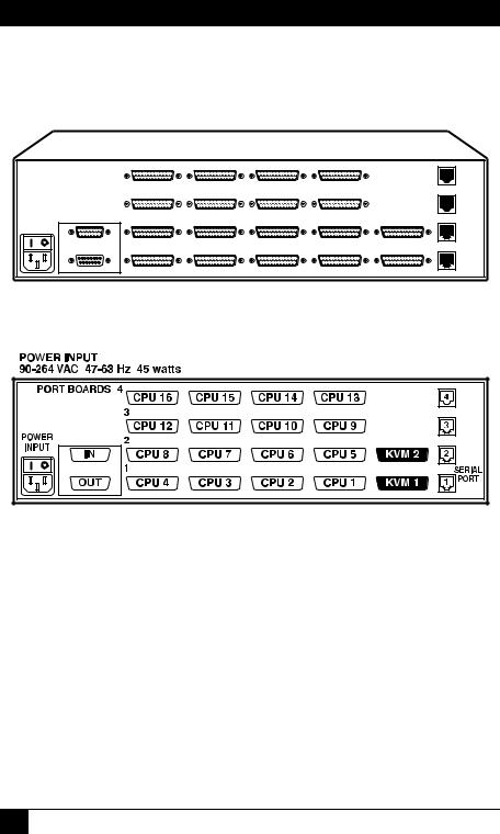
2.4 The Rear Panel
All cable connections are made at the Switch’s rear panel, as illustrated in Figures 2-2 and 2-3 and described below and on the next page.
Figure 2-2. The rear panel of a 2 x 16 Matrix ServSwitch with an Expansion Module installed.
Figure 2-3. The same rear panel, board and port numbering shown.
Designation |
Connector |
Description |
IN |
DB15 F |
On Expansion Module: Carries keyboard/mouse/ |
|
|
video data input from other Matrix ServSwitches to |
|
|
the local Switch. Run an Expansion Cable from this |
|
|
port to the OUT port on another Switch. |
OUT |
DB15 M |
On Expansion Module: Carries keyboard/mouse/ |
|
|
video data output from the local Matrix ServSwitch |
|
|
to other Switches. Run an Expansion Cable from |
|
|
this port to the IN port on another Switch. |
18

CHAPTER 2: Introduction
Designation |
Connector |
Description |
N [CPU N] |
DB25 F |
Connect the sharing computers to these ports with |
[N = a number |
|
CPU Cables. At the Matrix ServSwitch end, these |
from 1 to either |
|
cables have a DB25 male connector; at the other |
4, 8, or 16, |
|
ends, they have appropriate connectors to plug |
depending on |
|
into your CPUs’ video, keyboard, and mouse ports. |
which model you |
|
These cables take the signals that would normally |
have] |
|
pass between the CPUs’ ports and the monitor, |
|
|
keyboard, and mouse, and carry them between the |
|
|
CPUs’ ports and the Switch instead. You must have |
|
|
one CPU Cable for each CPU you plan to connect. |
|
|
See Section 2.5. |
|
|
NOTE |
|
|
The 2 x 4 and 2 x 8 chassis have 8 each |
|
|
of the CPU-port slots. The 2 x 16 chassis |
|
|
has 16 of them. The extra slots in the |
|
|
chassis of the 2 x 4 model are left blank, |
|
|
but are protected by material mounted |
|
|
inside the chassis. |
KVM 1 and |
DB25 F |
Connect the shared monitors, keyboards, and mice |
KVM 2 |
|
to this port using User Cables. At the Switch end, |
|
|
these cables have a DB25 male connector; at the |
|
|
other ends, they have appropriate connectors to |
|
|
plug into your monitor, keyboard, and mouse |
|
|
cables. See Section 2.5. |
RS-232 N |
RJ-12 F |
If you connect a more distant computer or |
[N = a number |
|
terminal to this RS-232 serial port, you’ll be able to |
from 1 to 1, 2, or |
|
send switching commands to the Matrix ServSwitch |
4, depending on |
|
from a secondary location. You would also connect |
which model you |
|
a computer to this port to upgrade the Switch’s |
have] |
|
firmware. Refer to Chapter 7. |
[POWER |
IEC 320 M |
Connect the Matrix ServSwitch’s power-supply cord |
INPUT] |
|
here. The Switch’s internal transformer is autosensing |
|
|
and can handle either 110-VAC or 230-VAC input. |
19
MATRIX SERVSWITCH™
2.5 Cable Requirements
Many switches of this type have what seems like ten million connectors on their rear panels: one for each CPU’s video cable, one for each keyboard cable, and a third for each mouse cable. The potential for tangling or mismatching cables is high.
By contrast, you can connect the Matrix ServSwitch to your CPUs with one CPU Cable (also called a “CPU Adapter Cable”) for each CPU. This single cable reaches the CPU’s video-output, keyboard, and mouse ports.
To connect other Matrix ServSwitches, you need two Matrix ServSwitch Expansion Cables for each chassis-to-chassis connection. (Each chassis also needs to have an Expansion Module installed in it.)
Finally, you can connect the Matrix ServSwitch to the shared monitors, keyboards, and mice with one User Cable (also called an “MKM Adapter Cable”) for each keyboard/monitor/mouse user station.
The exact variety or varieties of these cables that you’ll need will depend on the equipment you are connecting for your application. Refer to Appendix B for the available types of these cables and the corresponding product codes. Also refer to Chapter 1 and the Caution notice in Section 3.3.1 for information about maximum cabling distances.
NOTES
SVGA (over longer distances) and XGA video place special demands on cabling that the regular CPU Cables and User Cables typically cannot meet. For these applications, you should use coaxial cables that can carry video signals not only farther but also at higher resolutions. See Appendix B and the Caution notice in Section 3.3.1. You’ll also need a “Mac
Adapter for ServSwitch” (KV99MA) for each Mac CPU outputting high-res (greater than 640 x 480) video.
2.6 Equipment Requirements
If the CPUs you will be controlling through your Matrix ServSwitch are not all of the same type—especially if you’re using multiplatform Switches and the CPUs represent completely different hardware platforms (IBM, Sun, etc.)—you will have to be careful to choose a common monitor, keyboard, and mouse that adequately support all of the CPUs. For full details, see Section 3.2.
20
CHAPTER 3: Installation and Preconfiguration
3.Installation and Preconfiguration
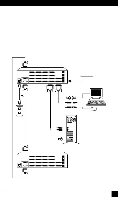
3.1Quick Setup Guide
Figure 3-1 shows a basic example of taking a Matrix ServSwitch and connecting it to a CPU, a user station (monitor, keyboard, and mouse), another Switch, and AC power. IBM PC equipment is shown, but the principles will be similar for all equipment types. Connectors will vary depending on the types of equipment you are installing.
Expansion Cable (forms ring, optional)
Primary 2 x 16 Matrix
ServSwitch (SW743A-R3)
|
Power |
|
UserCable |
|
cord |
ExpansionCable |
CPU Cable |
|
Keyboard |
|
Mouse |
6-wire modular cable to remote PC
Monitor
Keyboard
Mouse
Video card
Secondary 2 x 16 Matrix
ServSwitch (SW743A-R3)
Figure 3-1. Basic system setup.
21

MATRIX SERVSWITCH™
3.2 Guidelines for Using the Matrix ServSwitch with Your Equipment
3.2.1 CPUS
If you will be attaching IBM PC type computers, use only IBM PC/AT, PS/2, RS/6000®, or 100% compatible machines, or recent SGI® machines. The Matrix ServSwitch does not support IBM PC/XT™ or compatible machines. It also does not support machines that output CGA or EGA video. (Because the basic hardware design used by Apple and Sun has remained largely backward-compatible, the multiplatform Matrix Switches support most Sun machines and—with adapters— Apple machines.)
3.2.2 MOUSE AND KEYBOARD
When you power up your Matrix ServSwitch system, make sure that your CPUs, mice, and keyboards are properly cabled to the system. When you boot up your CPUs, the Matrix ServSwitches to which they are connected should already be ON. (You should be able to freely disconnect and reconnect the mouse or keyboard from a Matrix ServSwitch while the Switch is ON, but if you experience problems when you do this, issue the Reset command [CTRL] R—see Section 6.11.)
Though the Matrix ServSwitch can convert any supported keyboard or mouse protocol to any other, this is not enough to overcome all of the vast differences between input devices. If all of your CPUs are of the same type, we recommend that you use the corresponding type of keyboard and mouse. (However, the Switch doesn’t support Apple keyboards or mice, even though you can use adapters to attach Mac CPUs.) If your CPUs are of different types, certain limitations tend to favor the use of certain keyboard and mouse types:
Standard PC keyboards have 101 or 102 keys; PC keyboards designed specifically for modern versions of Microsoft® Windows® have 104 or 105 keys. At this time there is no way for a 101-/102-key keyboard to emulate the functions of the Windows Start ( 
 ) and Windows Application (

 ) keys on a 104-/105-key keyboard. And Type 5 Sun keyboards have 118 keys as well as keyclick and beep features. We have mapped several of the Apple and Sun keys to the PC keyboards (see Table 3-1 at the end of this section), but many of the Sun keys simply cannot be mapped to IBM keyboards. Similarly, standard PC mice have two or three buttons. At this time there is no way for a two-button mouse attached to the ServSwitch to emulate a mouse with three buttons.
For these reasons, we recommend that you use Sun Type 5 (not Type 6) keyboards and Sun mice with multiplatform Switches for mixed-platform applications that include Sun CPUs. Use IBM keyboards and mice for PC-only Switches, or with multiplatform Switches to which no Sun CPUs are attached. In
22

CHAPTER 3: Installation and Preconfiguration
particular, use Windows keyboards if any of your applications require the Windows keys, and use three-button mice if any of your applications require the center mouse button.
Other concerns:
•The Matrix ServSwitch emulates several types of mice for the attached computers, but the actual mice used at your user stations must be the same type as the stations’ keyboards: Sun mice with Sun keyboards or PS/2 mice (not serial mice) with PC type keyboards. For more details, see Section 4.3.
•Because the Switch currently only supports “stream mode” (continuous) mouse data, but older IBM ThinkPad models have to handle mouse data in “prompt mode” (burst-on-request), don’t try to attach any older ThinkPad computers to the Matrix ServSwitch, either directly or through docking stations. Some newer models should work with the Switch, but there’s no good way to tell other than by trial and error. (You can’t damage your equipment by trying—if you have the wrong kind of ThinkPad, it just won’t work.)
•If you’re using a PC mouse as the common mouse, make sure that your IBM PC CPUs use only the generic Microsoft® mouse driver MOUSE.COM, version 4.0 at least and preferably version 9.01 or higher. If you’re running Windows 3.x, this driver must be loaded in Windows as well as in the base operating system. Do not, on any of your switched IBM PC CPUs, run any programs or TSRs, or enter any DOS commands, that change the settings of the mouse port after the driver has been loaded.
•When you first switch between CPUs, especially CPUs of different platforms, you might notice wide variations in mouse sensitivity (how far or fast the mouse moves) from CPU to CPU. This is normal. There are ways to adjust the sensitivity of the mouse. (This is usually handled through some kind of software “control panel,” but the specifics vary depending on the operating system and—in IBM applications—on the mouse driver.) To optimize mouse movement, adjust the sensitivity on each CPU according to your individual preference.
•Although the Matrix ServSwitch resists minor transient surges that can be caused by rapidly cycling power, certain keyboards are sensitive to such transients. Because your shared keyboard’s power is provided by the Matrix ServSwitch, wait at least three seconds after powering down the Switch before powering it up again, or the keyboard might not reset correctly.
23

MATRIX SERVSWITCH™
•The Matrix ServSwitch is designed to support IBM PC compatible 101-, 102-, 104-, or 105-key keyboards and IBM PC keyboard-scan modes 1, 2, and 3; it’s also designed to work with PC-type CPUs/keyboards that use 5-pin DIN or 6-pin mini-DIN keyboard connectors. The Matrix ServSwitch will try to pass through keyboard codes that it doesn’t recognize without altering them, which allows it to support the DEC LK461 keyboard (see Appendix D for the key mappings), Japanese 106and 109-key keyboards, and certain other keyboards that use special or proprietary keys. However, we cannot guarantee that the Switch will be able to fully support—or even work at all with—any PC-type keyboard that uses nonstandard keys, connectors, or keyboard-scan modes.
•If you are using a Sun keyboard, it must be a Type 5 or Type 5c model, not Type 6 (the Matrix ServSwitch isn’t yet fully Type 6 compatible). If the keyboard is designed for a keyboard language other than “US” (standard North American English), you’ll need to select the language under “Keyboard settings” in the Configure System page of the configuration menu (see
Section 4.2.2).
24
CHAPTER 3: Installation and Preconfiguration
Table 3-1. Keyboard mapping by the Matrix ServSwitch.
Generally, the Matrix ServSwitch interprets keys by their positions on the keyboard, so any keys that occupy more or less the same positions and perform more or less the same functions across platforms will map one-to-one. However, certain keys available on certain keyboards do not correspond well or are not available on other types of keyboards, so the Switch maps the more important of these as shown below. (The Switch does not support Apple keyboards, but with the proper adapter it will emulate an Apple keyboard to an attached Mac CPU.)
On the Sun |
Emulates the |
Emulates the |
|
|
|
|
|
Emulates the |
|
keyboard, the |
PC 101/102-key |
PC 104/105-key |
|
|
|
|
|
Apple keyboard’s |
|
___ key: |
keyboard’s ___ key: |
keyboard’s ___ key: |
___ key: |
||||||
Control |
Left Ctrl |
Left Ctrl |
|
|
|
|
|
Left Control |
|
Alt |
Left Alt |
Left Alt |
|
|
|
|
|
Left Option (alt) |
|
Left Command ( ) |
N/A |
Left Win Start ( |
|
|
) |
Left Command ( ) |
|||
|
|||||||||
Right Command ( ) |
N/A |
Right Win Start ( |
|
|
|
|
) |
Right Command ( ) |
|
|
|||||||||
Compose |
Right Ctrl |
Right Ctrl |
|
|
|
|
|
Right Control |
|
Alt Graph |
Right Alt or Alt Graph |
Right Alt or Alt Graph |
Right Option (alt) |
||||||
Power ( |) |
N/A |
Windows App ( |
|
) |
Power ( ) |
||||
|
|||||||||
|
|
|
|
|
|
|
|
|
|
On the IBM PC 101/ 102-key keyboard, the ___ key:
Left Ctrl
Left Alt
Right Alt or Alt Graph Right Ctrl
(Maps to same |
Emulates the |
(Not recommended) |
key on PC 104/ |
Apple keyboard’s |
Emulates the Sun |
105-key keyboard.) |
___ key: |
keyboard’s ___ key: |
|
Left Control |
Left Control |
|
Left Command ( ) |
Left Command ( ) |
|
Right Option (alt) |
Alt Graph |
|
Power ( ) |
Power ( |) |
On the IBM PC 104/ |
(Natively supports |
Emulates the |
(Not recommended) |
||||||
105-key keyboard, |
PC 101/102-key |
Apple keyboard’s |
Emulates the Sun |
||||||
the ___ key: |
|
|
|
|
|
keyboard functions.) |
___ key: |
keyboard’s ___ key: |
|
Left Ctrl |
|
|
|
|
|
|
Left Control |
Left Control |
|
Left Win Start ( |
|
|
) |
|
Left Command ( ) |
Left Command ( ) |
|||
|
|
||||||||
|
|
||||||||
Left Alt |
|
|
|
|
|
|
Left Option (alt) |
Alt |
|
Right Alt or Alt Graph |
|
Right Option (alt) |
Alt Graph |
||||||
Right Win Start ( |
|
|
|
|
) |
|
Right Command ( ) |
Right Command ( ) |
|
|
|
||||||||
|
|
||||||||
Windows App ( |
|
) |
|
Power ( ) |
Power ( |) |
||||
Right Ctrl |
|
|
|
|
|
|
Right Control |
Compose |
|
|
|
|
|
|
|
|
|
|
|
25

MATRIX SERVSWITCH™
3.2.3 MONITOR
If all of your CPUs are of the same type, we recommend that you use the corresponding type of monitor. If your CPUs are of different types, the monitor must be a multisync model, able to sync to every CPU’s video-output frequencies, and compatible with all of the CPUs’ video cards.
While PC-type CPUs and VGA monitors normally use two separate leads to send/receive sync signals (one lead for horizontal sync and one for vertical sync, referred to as “H/V”), Mac and Sun CPUs/monitors normally send/receive a composite sync signal on a single lead. (So do some otherwise PC-compatible CPUs, including many SGI models.) If you attach both H/V and composite-sync CPUs to your system, either your monitor must be capable of accepting both H/V and composite-sync input, or you’ll have to use a sync converter and special cables to convert H/V to composite sync or vice versa (call Black Box Technical Support for a special quote).
For maximum compatibility, we recommend a 17" or larger, high-quality multisync monitor capable of (a) displaying a maximum resolution of not less than 1280 x 1024 at a maximum refresh rate of not less than 75 Hz, and (b) accepting both relevant types of sync input (H/V and composite). Such monitors are available from many manufacturers. (However, since these monitors usually have an HD15 video-input connector, you will need a special User Cable to use them with Sun keyboards and mice; this cable is product code EHN059 [original] or EHN225 [coax].) The higher the resolution you use, the less distance you can run; see Tables 3-2 and 3-3 on the following pages.
Other concerns specific to IBM PCs:
•The Matrix ServSwitch is designed to support standard VGA video, including VGA monochrome (“page white”). It does not support PCs that use CGA, EGA, or proprietary versions of VGA that depart from the original specifications. Consult your PC’s manual, and if that doesn’t tell you whether or not the PC uses standard VGA, consult with the PC’s or the video card’s manufacturer.
•The Switch is also designed to support SVGA, although it doesn’t handle higher resolutions or longer distances very well without coaxial cabling (see the next two pages). With coaxial cables, it will also support XGA, RS/6000, and SGI video (RS/6000 and SGI require cables with 13W3 connectors—see
Appendix B).
If you have Mac CPUs attached, you’ll need a Mac Adapter for ServSwitch (product code KV99MA) for each CPU that outputs video in a format other than VGA (640 x 480).
26

CHAPTER 3: Installation and Preconfiguration
The Matrix ServSwitch will support SVGA (Super VGA) video, but with original Serv cables the video quality can decrease at higher resolutions and distances. Table 3-2 illustrates this. The distances in the table are total lengths of CPU Cable and User Cable (but not Expansion Cable) measured from the CPU to the monitor. The table assumes that one Matrix ServSwitch is between the CPU and monitor; in a daisychained application with multiple Matrix ServSwitches between the CPU and monitor, video quality will always be lower.
This table also applies to Mac video in Matrix ServSwitch systems in which the Mac version of the original Serv type CPU Cable (product code EHN215) has been installed.
Table 3-2. Video quality vs. distance for original Serv cables.
Distance |
5' (1.5 m) |
10' (3 m) |
15' (4.6 m) |
20' (6.1 m) |
25' (7.6 m) |
Resolution |
|
|
|
|
|
|
|
|
|
|
|
640 x 480 |
3 |
3 |
3 |
3 |
3 |
|
|
|
|
|
|
800 x 600 noninterlaced |
3 |
3 |
3 |
3 |
2 |
|
|
|
|
|
|
1024 x 768 interlaced |
3 |
3 |
3 |
2 |
2 |
|
|
|
|
|
|
1024 x 768 noninterlaced |
3 |
3 |
2 |
2 |
2 |
|
|
|
|
|
|
1280 x 1024 interlaced |
3 |
2 |
2 |
2 |
1 |
|
|
|
|
|
|
1280 x 1024 noninterlaced |
2 |
2 |
2 |
1 |
1 |
|
|
|
|
|
|
1600 x 1280 |
2 |
2 |
1 |
1 |
1 |
|
|
|
|
|
|
Quality 3 = Near perfect; screen defects are not conspicuous
Quality 2 = Good to very good; images are clear; there are small reflections around text lettering depending on the color; screen defects are sometimes conspicuous
Quality 1 = Fair to poor as distance increases; images run from slightly fuzzy to badly smeared; text runs from fuzzy but readable to completely washed out
27

MATRIX SERVSWITCH™
By contrast, coaxial cables (standard for Sun applications, required for XGA applications, and recommended for most other applications) do much better at maintaining video quality, as shown in Table 3-3. (For the meaning of quality numbers 3, 2, and 1, see the bottom of the previous page.) As before, the distances in the table are total adapter-cable lengths (not including Expansion Cable) measured from the CPU to the monitor. Also as before, the table assumes a single Matrix ServSwitch is between the CPU and monitor; if there are other chained Switches as well, video quality will always be lower. (Where “interlaced” or “noninterlaced” isn’t specified, noninterlaced video is implied.)
Table 3-3. Video quality vs. distance for coaxial cables.
Distance |
10 ft. |
20 ft. |
30 ft. |
50 ft. |
75 ft. |
100 ft. |
150 ft. |
200 ft. |
Resolution |
(3 m) |
(6.1 m) |
(9.1 m) |
(15.2 m) |
(22.9 m) |
(30.5 m) |
(45.7 m) |
(61 m) |
|
||||||||
|
|
|
|
|
|
|
|
|
640 x 480 |
3 |
3 |
3 |
3 |
3 |
3 |
3 |
3 |
|
|
|
|
|
|
|
|
|
800 x 600 |
3 |
3 |
3 |
3 |
3 |
3 |
3 |
2 |
|
|
|
|
|
|
|
|
|
1024 x 768 interlaced |
3 |
3 |
3 |
3 |
3 |
3 |
2 |
2 |
|
|
|
|
|
|
|
|
|
1024 x 768 noninterl. |
3 |
3 |
3 |
3 |
3 |
2 |
2 |
1 |
|
|
|
|
|
|
|
|
|
1280 x 1024 interlaced |
3 |
3 |
3 |
3 |
2 |
2 |
1 |
1 |
|
|
|
|
|
|
|
|
|
1280 x 1024 noninterl. |
3 |
3 |
3 |
2 |
2 |
1 |
1 |
1 |
|
|
|
|
|
|
|
|
|
1600 x 1280 |
3 |
3 |
2 |
2 |
1 |
1 |
1 |
1 |
|
|
|
|
|
|
|
|
|
CAUTION!
Some CPUs can’t drive or receive keyboard and mouse signals across longer runs of coaxial cable. Consult with the manufacturers of your CPUs before installing this cable in lengths greater than 20 ft. (6.1 m).
If all of your CPUs are IBM PC compatible, and you want to drive signals across CPU-to-Switch or Switch-to-monitor distances over 100 feet (30.5 m), you might require Station Extenders or CAT5 KVM Extenders (see Appendix B). Please call Black Box Technical Support to discuss your application.
28

CHAPTER 3: Installation and Preconfiguration
3.3 Installation Procedure
This section provides complete instructions for the hardware setup of a single Matrix ServSwitch. (For detailed instructions on installing a daisychained Matrix ServSwitch system, see Sections 3.3.6 and 3.4.) For an illustrated example of the elements of a basic setup, see Figure 3-1.
For the procedure you should use to power up the system, see Section 3.5. For the initial configuration procedure, see Section 3.6.
IMPORTANT NOTE
Initially configuring a Matrix ServSwitch will require you to either attach a monitor, keyboard, and mouse to one of its KVM ports or to attach a complete computer system to one of its serial ports. If this attachment will be difficult to make after a particular Switch has been physically installed in a given location, you should configure that Switch before you install it; see Section 3.6.
3.3.1 PLACEMENT
The Matrix ServSwitch is best located as close as possible to the CPUs that are attached to it. This reduces the length of CPU cables and provides a more costeffective, neater installation. You should also place the Switch as close as possible to the AC outlet you want to plug it into.
CAUTION!
Avoid routing cable near fluorescent lights, air-conditioning compressors, or machines that may create electrical noise. Total length of original Serv type CPU or User Cable (not including Expansion Cable) from the keyboard, monitor, and mouse to any given CPU should not exceed 40 ft. (12.2 m). For typical equipment and video resolutions, length of coaxial CPU or User Cable (again, not including Expansion Cable) should not exceed 20 ft. (6.1 m) from a Matrix ServSwitch to any attached device (keyboard, monitor, mouse, CPU, or other KVM switch). However, we do provide coaxial cable in lengths up to 100 ft. (30.5 m), because some CPUs can drive and receive keyboard and mouse signals at greater distances than others. To go even farther, you might want to use Station Extenders or CAT5 KVM Extenders (see Appendix B).
3.3.2 SETTING AND INSTALLING THE OPTIONAL EXPANSION MODULE
At any time, you can swap in an Expansion Module for the Terminator Module in the Matrix ServSwitch’s Expansion slot, in order to prepare the Switch to be daisychained. Depending on the topology of your daisychained system, you might need to set the Expansion Module’s JP1 jumper before you do this. For directions, see Appendix E.
29
 Loading...